DODGE TOWN AND COUNTRY 2001 Service Manual
Manufacturer: DODGE, Model Year: 2001, Model line: TOWN AND COUNTRY, Model: DODGE TOWN AND COUNTRY 2001Pages: 2321, PDF Size: 68.09 MB
Page 1731 of 2321
in 3rd and 4th gear Autostick mode. Speed control
will be deactivated if the transaxle is shifted to 2nd
gear. Shifting into OD position cancels the Autostick
mode, and the transaxle resumes the OD shift sched-
ule.
DRIVING CLUTCHES
DESCRIPTION
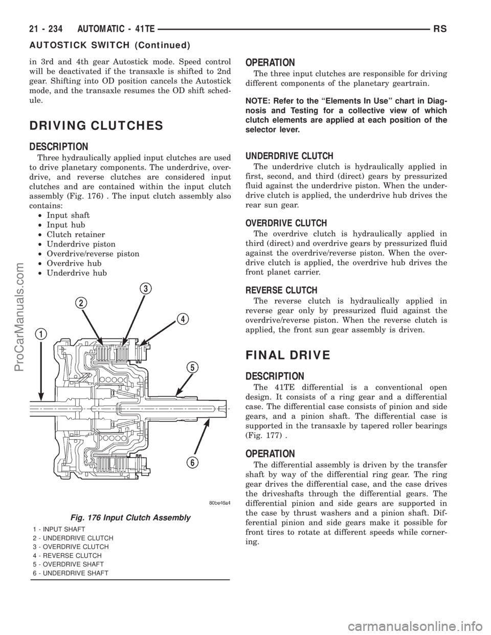
Three hydraulically applied input clutches are used
to drive planetary components. The underdrive, over-
drive, and reverse clutches are considered input
clutches and are contained within the input clutch
assembly (Fig. 176) . The input clutch assembly also
contains:
²Input shaft
²Input hub
²Clutch retainer
²Underdrive piston
²Overdrive/reverse piston
²Overdrive hub
²Underdrive hub
OPERATION
The three input clutches are responsible for driving
different components of the planetary geartrain.
NOTE: Refer to the ªElements In Useº chart in Diag-
nosis and Testing for a collective view of which
clutch elements are applied at each position of the
selector lever.
UNDERDRIVE CLUTCH
The underdrive clutch is hydraulically applied in
first, second, and third (direct) gears by pressurized
fluid against the underdrive piston. When the under-
drive clutch is applied, the underdrive hub drives the
rear sun gear.
OVERDRIVE CLUTCH
The overdrive clutch is hydraulically applied in
third (direct) and overdrive gears by pressurized fluid
against the overdrive/reverse piston. When the over-
drive clutch is applied, the overdrive hub drives the
front planet carrier.
REVERSE CLUTCH
The reverse clutch is hydraulically applied in
reverse gear only by pressurized fluid against the
overdrive/reverse piston. When the reverse clutch is
applied, the front sun gear assembly is driven.
FINAL DRIVE
DESCRIPTION
The 41TE differential is a conventional open
design. It consists of a ring gear and a differential
case. The differential case consists of pinion and side
gears, and a pinion shaft. The differential case is
supported in the transaxle by tapered roller bearings
(Fig. 177) .
OPERATION
The differential assembly is driven by the transfer
shaft by way of the differential ring gear. The ring
gear drives the differential case, and the case drives
the driveshafts through the differential gears. The
differential pinion and side gears are supported in
the case by thrust washers and a pinion shaft. Dif-
ferential pinion and side gears make it possible for
front tires to rotate at different speeds while corner-
ing.
Fig. 176 Input Clutch Assembly
1 - INPUT SHAFT
2 - UNDERDRIVE CLUTCH
3 - OVERDRIVE CLUTCH
4 - REVERSE CLUTCH
5 - OVERDRIVE SHAFT
6 - UNDERDRIVE SHAFT
21 - 234 AUTOMATIC - 41TERS
AUTOSTICK SWITCH (Continued)
ProCarManuals.com
Page 1732 of 2321
DISASSEMBLY
NOTE: The differential is serviced as an assembly.
Differential service is limited to bearing cups and
cones. Any other differential component failure
must be remedied by differential assembly and
transfer shaft replacement.
The transfer shaft should be removed for differen-
tial repair and bearing turning torque checking.
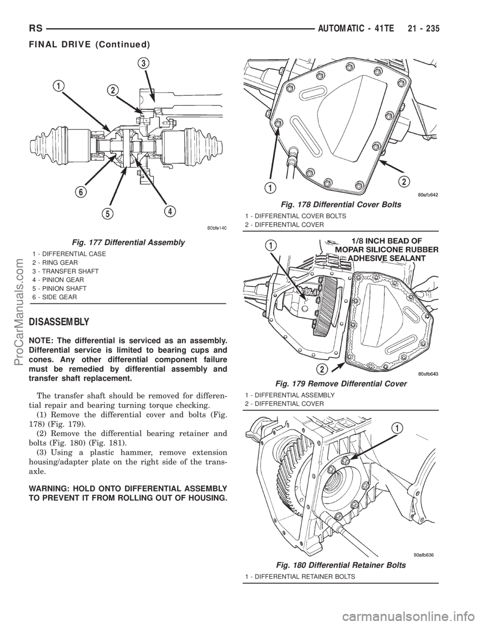
(1) Remove the differential cover and bolts (Fig.
178) (Fig. 179).
(2) Remove the differential bearing retainer and
bolts (Fig. 180) (Fig. 181).
(3) Using a plastic hammer, remove extension
housing/adapter plate on the right side of the trans-
axle.
WARNING: HOLD ONTO DIFFERENTIAL ASSEMBLY
TO PREVENT IT FROM ROLLING OUT OF HOUSING.
Fig. 177 Differential Assembly
1 - DIFFERENTIAL CASE
2 - RING GEAR
3 - TRANSFER SHAFT
4 - PINION GEAR
5 - PINION SHAFT
6 - SIDE GEAR
Fig. 178 Differential Cover Bolts
1 - DIFFERENTIAL COVER BOLTS
2 - DIFFERENTIAL COVER
Fig. 179 Remove Differential Cover
1 - DIFFERENTIAL ASSEMBLY
2 - DIFFERENTIAL COVER
Fig. 180 Differential Retainer Bolts
1 - DIFFERENTIAL RETAINER BOLTS
RSAUTOMATIC - 41TE21 - 235
FINAL DRIVE (Continued)
ProCarManuals.com
Page 1733 of 2321
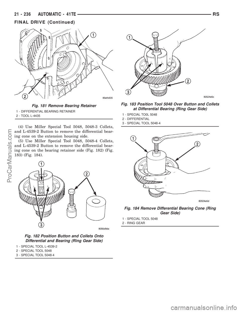
(4) Use Miller Special Tool 5048, 5048-3 Collets,
and L-4539-2 Button to remove the differential bear-
ing cone on the extension housing side.
(5) Use Miller Special Tool 5048, 5048-4 Collets,
and L-4539-2 Button to remove the differential bear-
ing cone on the bearing retainer side (Fig. 182) (Fig.
183) (Fig. 184).
Fig. 181 Remove Bearing Retainer
1 - DIFFERENTIAL BEARING RETAINER
2 - TOOL L-4435
Fig. 182 Position Button and Collets Onto
Differential and Bearing (Ring Gear Side)
1 - SPECIAL TOOL L-4539-2
2 - SPECIAL TOOL 5048
3 - SPECIAL TOOL 5048-4
Fig. 183 Position Tool 5048 Over Button and Collets
at Differential Bearing (Ring Gear Side)
1 - SPECIAL TO0L 5048
2 - DIFFERENTIAL
3 - SPECIAL TOOL 5048-4
Fig. 184 Remove Differential Bearing Cone (Ring
Gear Side)
1 - SPECIAL TOOL 5048
2 - RING GEAR
21 - 236 AUTOMATIC - 41TERS
FINAL DRIVE (Continued)
ProCarManuals.com
Page 1734 of 2321
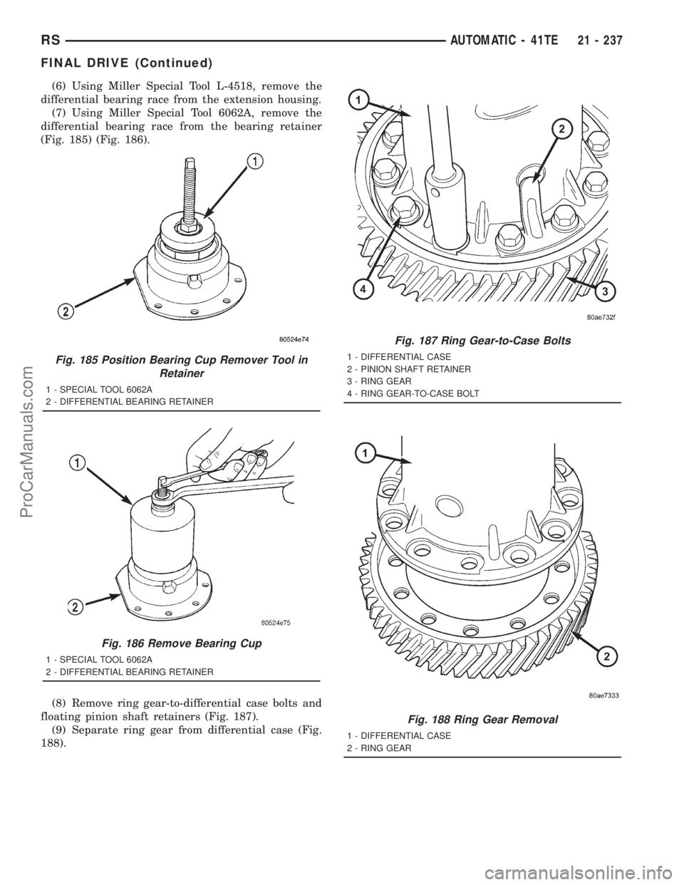
(6) Using Miller Special Tool L-4518, remove the
differential bearing race from the extension housing.
(7) Using Miller Special Tool 6062A, remove the
differential bearing race from the bearing retainer
(Fig. 185) (Fig. 186).
(8) Remove ring gear-to-differential case bolts and
floating pinion shaft retainers (Fig. 187).
(9) Separate ring gear from differential case (Fig.
188).
Fig. 185 Position Bearing Cup Remover Tool in
Retainer
1 - SPECIAL TOOL 6062A
2 - DIFFERENTIAL BEARING RETAINER
Fig. 186 Remove Bearing Cup
1 - SPECIAL TOOL 6062A
2 - DIFFERENTIAL BEARING RETAINER
Fig. 187 Ring Gear-to-Case Bolts
1 - DIFFERENTIAL CASE
2 - PINION SHAFT RETAINER
3 - RING GEAR
4 - RING GEAR-TO-CASE BOLT
Fig. 188 Ring Gear Removal
1 - DIFFERENTIAL CASE
2 - RING GEAR
RSAUTOMATIC - 41TE21 - 237
FINAL DRIVE (Continued)
ProCarManuals.com
Page 1735 of 2321
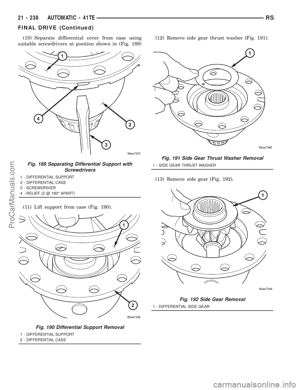
(10) Separate differential cover from case using
suitable screwdrivers at position shown in (Fig. 189)
(11) Lift support from case (Fig. 190).(12) Remove side gear thrust washer (Fig. 191).
(13) Remove side gear (Fig. 192).
Fig. 189 Separating Differential Support with
Screwdrivers
1 - DIFFERENTIAL SUPPORT
2 - DIFFERENTIAL CASE
3 - SCREWDRIVER
4 - RELIEF (2 @ 180É APART)
Fig. 190 Differential Support Removal
1 - DIFFERENTIAL SUPPORT
2 - DIFFERENTIAL CASE
Fig. 191 Side Gear Thrust Washer Removal
1 - SIDE GEAR THRUST WASHER
Fig. 192 Side Gear Removal
1 - DIFFERENTIAL SIDE GEAR
21 - 238 AUTOMATIC - 41TERS
FINAL DRIVE (Continued)
ProCarManuals.com
Page 1736 of 2321
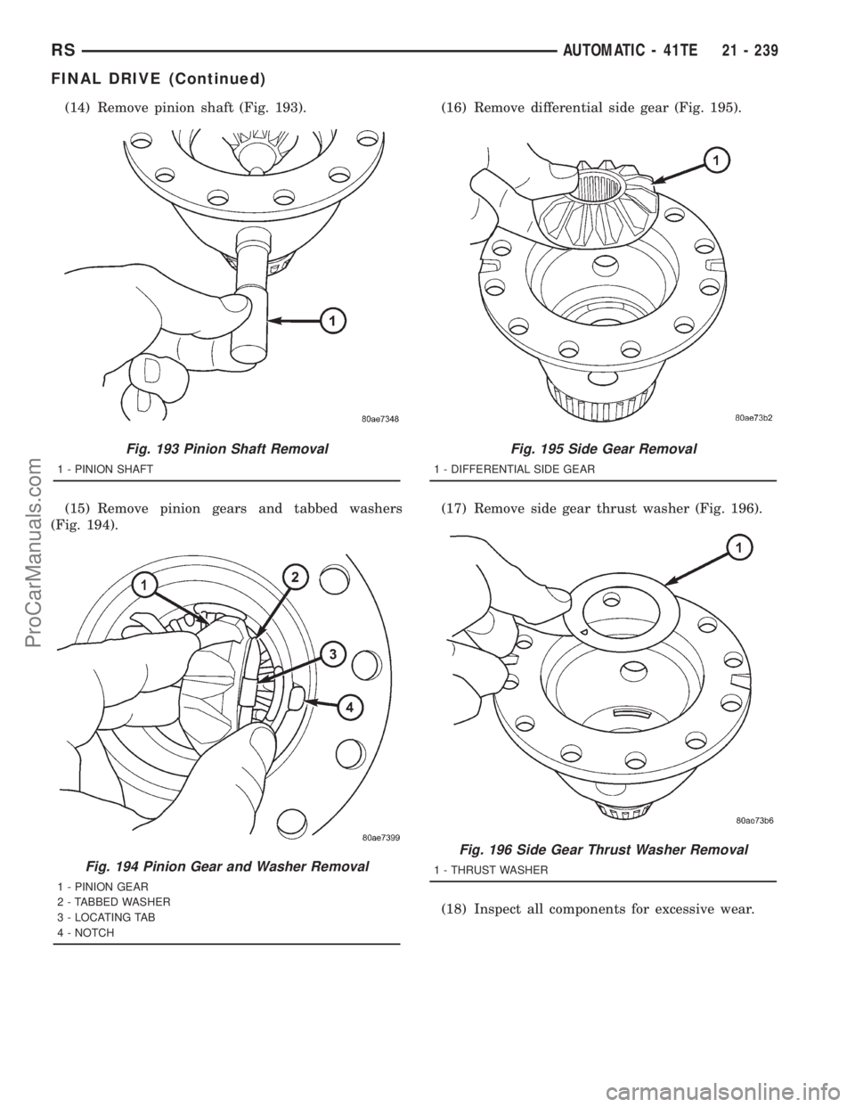
(14) Remove pinion shaft (Fig. 193).
(15) Remove pinion gears and tabbed washers
(Fig. 194).(16) Remove differential side gear (Fig. 195).
(17) Remove side gear thrust washer (Fig. 196).
(18) Inspect all components for excessive wear.
Fig. 193 Pinion Shaft Removal
1 - PINION SHAFT
Fig. 194 Pinion Gear and Washer Removal
1 - PINION GEAR
2 - TABBED WASHER
3 - LOCATING TAB
4 - NOTCH
Fig. 195 Side Gear Removal
1 - DIFFERENTIAL SIDE GEAR
Fig. 196 Side Gear Thrust Washer Removal
1 - THRUST WASHER
RSAUTOMATIC - 41TE21 - 239
FINAL DRIVE (Continued)
ProCarManuals.com
Page 1737 of 2321
ASSEMBLY
NOTE: The differential is serviced as an assembly.
Differential service is limited to bearing cups and
cones. Any other differential component failure
must be remedied by differential assembly and
transfer shaft replacement.
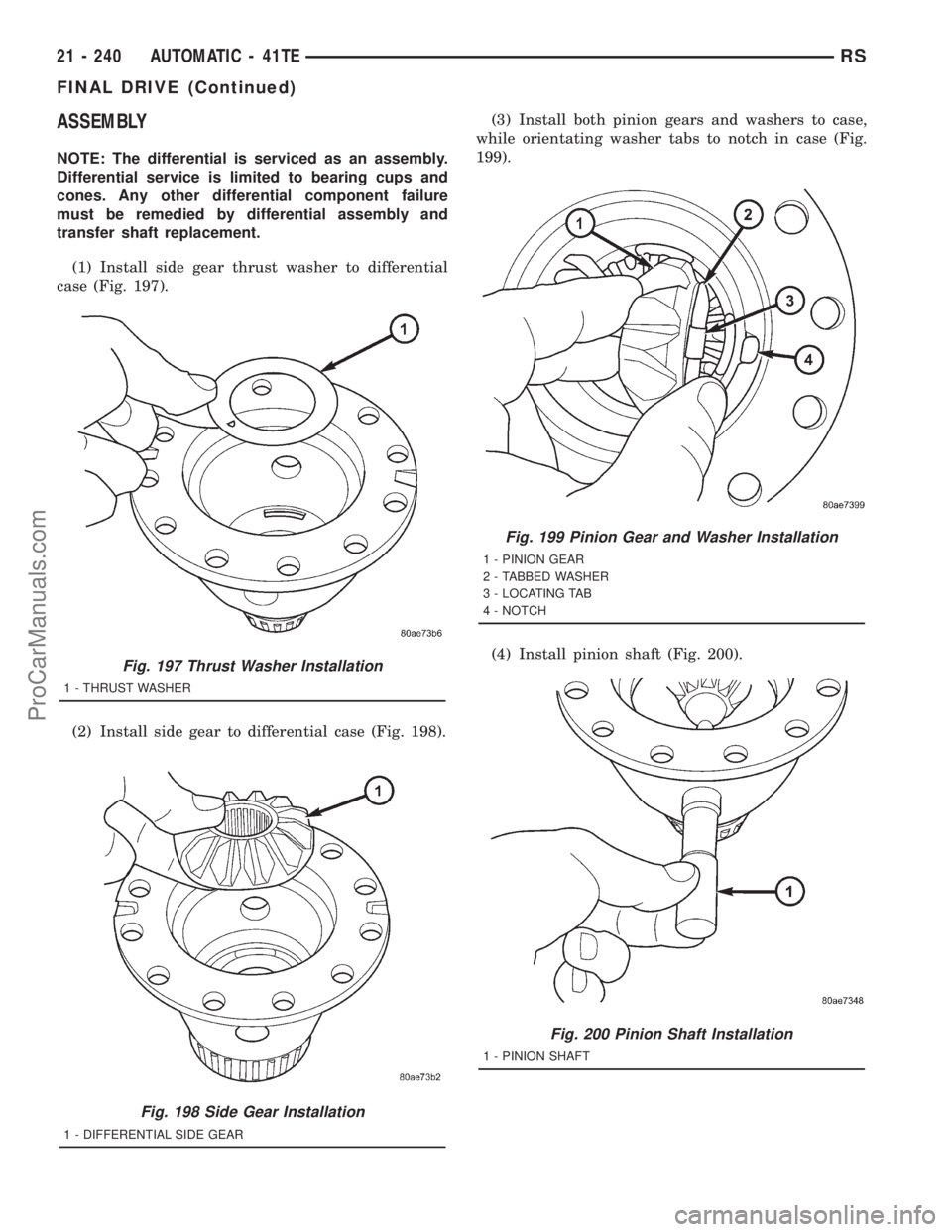
(1) Install side gear thrust washer to differential
case (Fig. 197).
(2) Install side gear to differential case (Fig. 198).(3) Install both pinion gears and washers to case,
while orientating washer tabs to notch in case (Fig.
199).
(4) Install pinion shaft (Fig. 200).
Fig. 197 Thrust Washer Installation
1 - THRUST WASHER
Fig. 198 Side Gear Installation
1 - DIFFERENTIAL SIDE GEAR
Fig. 199 Pinion Gear and Washer Installation
1 - PINION GEAR
2 - TABBED WASHER
3 - LOCATING TAB
4 - NOTCH
Fig. 200 Pinion Shaft Installation
1 - PINION SHAFT
21 - 240 AUTOMATIC - 41TERS
FINAL DRIVE (Continued)
ProCarManuals.com
Page 1738 of 2321
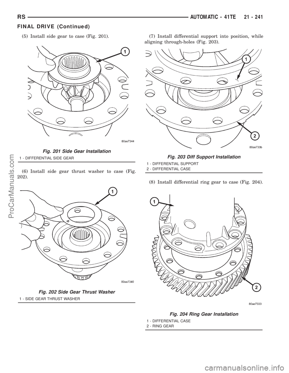
(5) Install side gear to case (Fig. 201).
(6) Install side gear thrust washer to case (Fig.
202).(7) Install differential support into position, while
aligning through-holes (Fig. 203).
(8) Install differential ring gear to case (Fig. 204).
Fig. 201 Side Gear Installation
1 - DIFFERENTIAL SIDE GEAR
Fig. 202 Side Gear Thrust Washer
1 - SIDE GEAR THRUST WASHER
Fig. 203 Diff Support Installation
1 - DIFFERENTIAL SUPPORT
2 - DIFFERENTIAL CASE
Fig. 204 Ring Gear Installation
1 - DIFFERENTIAL CASE
2 - RING GEAR
RSAUTOMATIC - 41TE21 - 241
FINAL DRIVE (Continued)
ProCarManuals.com
Page 1739 of 2321
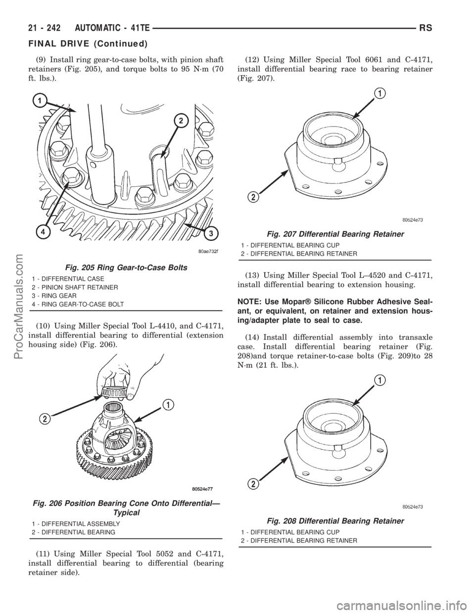
(9) Install ring gear-to-case bolts, with pinion shaft
retainers (Fig. 205), and torque bolts to 95 N´m (70
ft. lbs.).
(10) Using Miller Special Tool L-4410, and C-4171,
install differential bearing to differential (extension
housing side) (Fig. 206).
(11) Using Miller Special Tool 5052 and C-4171,
install differential bearing to differential (bearing
retainer side).(12) Using Miller Special Tool 6061 and C-4171,
install differential bearing race to bearing retainer
(Fig. 207).
(13) Using Miller Special Tool L±4520 and C-4171,
install differential bearing to extension housing.
NOTE: Use Moparž Silicone Rubber Adhesive Seal-
ant, or equivalent, on retainer and extension hous-
ing/adapter plate to seal to case.
(14) Install differential assembly into transaxle
case. Install differential bearing retainer (Fig.
208)and torque retainer-to-case bolts (Fig. 209)to 28
N´m (21 ft. lbs.).
Fig. 205 Ring Gear-to-Case Bolts
1 - DIFFERENTIAL CASE
2 - PINION SHAFT RETAINER
3 - RING GEAR
4 - RING GEAR-TO-CASE BOLT
Fig. 206 Position Bearing Cone Onto DifferentialÐ
Typical
1 - DIFFERENTIAL ASSEMBLY
2 - DIFFERENTIAL BEARING
Fig. 207 Differential Bearing Retainer
1 - DIFFERENTIAL BEARING CUP
2 - DIFFERENTIAL BEARING RETAINER
Fig. 208 Differential Bearing Retainer
1 - DIFFERENTIAL BEARING CUP
2 - DIFFERENTIAL BEARING RETAINER
21 - 242 AUTOMATIC - 41TERS
FINAL DRIVE (Continued)
ProCarManuals.com
Page 1740 of 2321
(15) Apply a bead of Moparž Silicone Rubber
Adhesive Sealant to extension housing/adapter plate
and install into position. Install and torque bolts to
28 N´m (21 ft. lbs.).
(16) Measure and adjust differential bearing pre-
load. (Refer to 21 - TRANSMISSION/TRANSAXLE/
AUTOMATIC - 41TE/FINAL DRIVE -
ADJUSTMENTS)
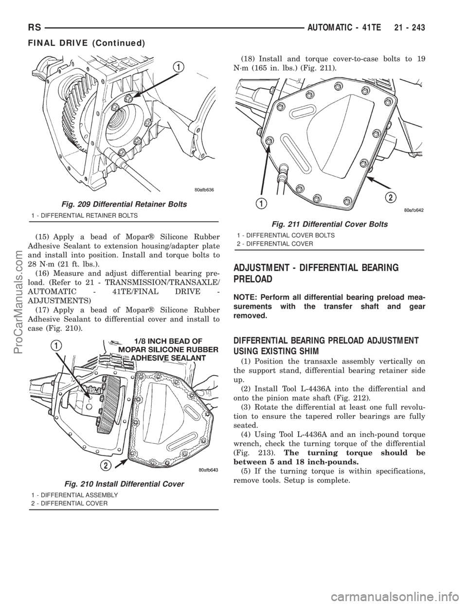
(17) Apply a bead of Moparž Silicone Rubber
Adhesive Sealant to differential cover and install to
case (Fig. 210).(18) Install and torque cover-to-case bolts to 19
N´m (165 in. lbs.) (Fig. 211).
ADJUSTMENT - DIFFERENTIAL BEARING
PRELOAD
NOTE: Perform all differential bearing preload mea-
surements with the transfer shaft and gear
removed.
DIFFERENTIAL BEARING PRELOAD ADJUSTMENT
USING EXISTING SHIM
(1) Position the transaxle assembly vertically on
the support stand, differential bearing retainer side
up.
(2) Install Tool L-4436A into the differential and
onto the pinion mate shaft (Fig. 212).
(3) Rotate the differential at least one full revolu-
tion to ensure the tapered roller bearings are fully
seated.
(4) Using Tool L-4436A and an inch-pound torque
wrench, check the turning torque of the differential
(Fig. 213).The turning torque should be
between 5 and 18 inch-pounds.
(5) If the turning torque is within specifications,
remove tools. Setup is complete.
Fig. 209 Differential Retainer Bolts
1 - DIFFERENTIAL RETAINER BOLTS
Fig. 210 Install Differential Cover
1 - DIFFERENTIAL ASSEMBLY
2 - DIFFERENTIAL COVER
Fig. 211 Differential Cover Bolts
1 - DIFFERENTIAL COVER BOLTS
2 - DIFFERENTIAL COVER
RSAUTOMATIC - 41TE21 - 243
FINAL DRIVE (Continued)
ProCarManuals.com