ABS DODGE TRUCK 1993 Service Owners Manual
[x] Cancel search | Manufacturer: DODGE, Model Year: 1993, Model line: TRUCK, Model: DODGE TRUCK 1993Pages: 1502, PDF Size: 80.97 MB
Page 1300 of 1502
•
TRANSMISSION
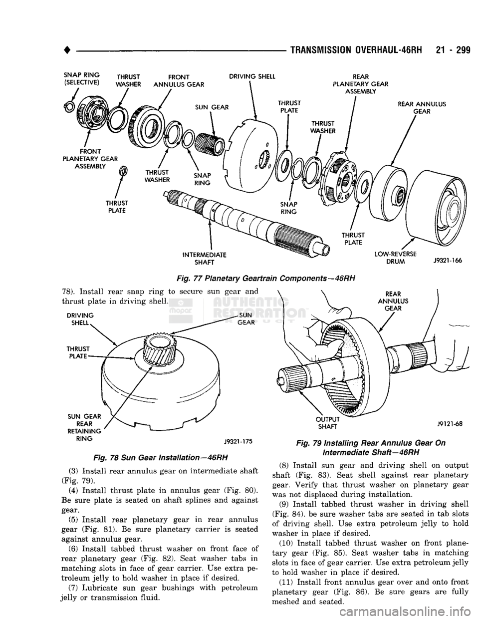
QVERHAUL-46RH
21 - 299
Fig.
77 Planetary
Geartrain
Components—46
RH 78).
Install rear snap ring to secure sun gear and
thrust plate in driving shell. J932M75
Fig.
78 Sun Gear Installation—46RH (3) Install rear annulus gear on intermediate shaft
(Fig. 79).
(4) Install thrust plate in annulus gear (Fig. 80).
Be sure plate is seated on shaft splines and against gear.
(5) Install rear planetary gear in rear annulus
gear (Fig. 81). Be sure planetary carrier is seated
against annulus gear.
(6) Install tabbed thrust washer on front face of
rear planetary gear (Fig. 82). Seat washer tabs in
matching slots in face of gear carrier. Use extra pe
troleum jelly to hold washer in place if desired.
(7) Lubricate sun gear bushings with petroleum
jelly or transmission fluid.
Fig.
79 Installing Rear
Annulus
Gear On
Intermediate
Shaft—46RH (8) Install sun gear and driving shell on output
shaft (Fig. 83). Seat shell against rear planetary
gear. Verify that thrust washer on planetary gear
was not displaced during installation.
(9) Install tabbed thrust washer in driving shell
(Fig. 84). be sure washer tabs are seated in tab slots
of driving shell. Use extra petroleum jelly to hold
washer in place if desired.
(10) Install tabbed thrust washer on front plane
tary gear (Fig. 85). Seat washer tabs in matching slots in face of gear carrier. Use extra petroleum jelly
to hold washer in place if desired.
(11) Install front annulus gear over and onto front
planetary gear (Fig. 86). Be sure gears are fully
meshed and seated.
Page 1429 of 1502
23
- 46
BODY
COMPONENTS
• (3) Bucket seats—detach the covers from the an
chor bolts for the left and right shoulder belt buckles.
(4) Remove the anchor bolts from the anchor plates
on the floor panel.
(5)
Remove the buckles and the lap belt from the
floor panel.
• Ram Trucks and Chassis Cabs—Remove the cover
concealing the shoulder belt upper anchor bolt.
• Ramchargers—Remove the quarter window trim
panel. If necessary, refer to the removal procedure.
(6) Remove the upper anchor bolt from the cab in
ner side panel/B-pillar.
• Ram Trucks and Chassis Cabs—Remove the shoul
der belt retractor and lower anchor bolt from the B-pillar.
• Ramchargers—Remove the screw and belt retrac
tor cover from the side inner panel. Remove the an chor bolts. Remove the retractor and lower belt from
the side inner panel.
(7) Remove the shoulder belts and retractors from
the vehicle.
INSTALLATION
(1) Position the shoulder belt retractor and the
lower end of the shoulder belt at the side inner
panel. Align the anchor bolt holes. Install the anchor
bolts.
Tighten the anchor bolts to 40 N*m (350 in. lbs.) torque.
• Ramchargers—Install the belt retractor cover and
the screw in the side inner panel. Tighten the screw
to 1 N»m (12 in. lbs.) torque.
(2) Position the shoulder belt upper anchor plate
on the trim panel. Install the upper anchor bolts in
the side panels. Tighten the anchor bolts to 40 N#m (350 in. lbs.) torque.
• Ram Trucks and Chassis Cabs—Install the cover
to conceal the shoulder belt upper anchor bolt.
• Ramchargers—Install the quarter window trim
panel. If necessary, refer to the installation proce
dure.
(3) Position the belt buckles on the floor panel.
(4) Install the shoulder belt buckles. Install the lap
belt and buckle anchor bolts in the floor panel.
Tighten the anchor bolts to 40 N«m (350 in. lbs.) torque.
• Bucket seats—Position the covers over the left and
right shoulder belt buckle anchor bolts.
(5) Connect the shoulder belt warning wire har
ness connectors. (6) If moved all the way forward for access, cor
rectly position the front seat.
REAR
SHOULDER
BELTS/LAP
BELT/BUCKLES-RAMCHARGER
REMOVAL
(1) If necessary, move the front seat(s) all the way
forward for access.
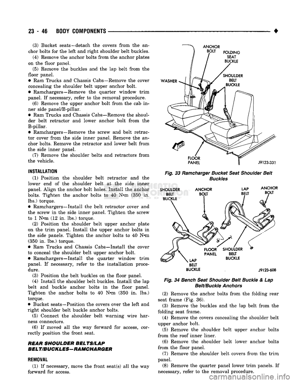
Fig.
33
Ramcharger
Bucket
Seat
Shoulder
Belt
Buckles
SHOULDER
ANCHOR
LAP
BELT
BUCKLE
.
J9123-608
Fig.
34
Bench
Seat
Shoulder
Belt
Buckle
& Lap
Belt/Buckle
Anchors
(2) Remove the anchor bolts from the folding rear
seat frame (Fig. 36). (3) Remove the buckles and the lap belt from the
folding seat frame. (4) Remove the covers concealing the shoulder belt
upper anchor bolt.
(5) Remove the shoulder belt upper anchor bolts
from the roof inner liner.
(6) Remove the shoulder belt lower anchor bolts
from the floor panel.
(7) Remove the shoulder belt covers from the trim
panel.
(8) Remove the quarter panel lower trim panels. If
necessary, refer to the removal procedure.
Page 1431 of 1502
23
- 48
BODY COMPONENTS
JUMP SEAT LAP BELT/BUCKLE
REMOVAL
(1) If necessary, move the front seat(s) all the way
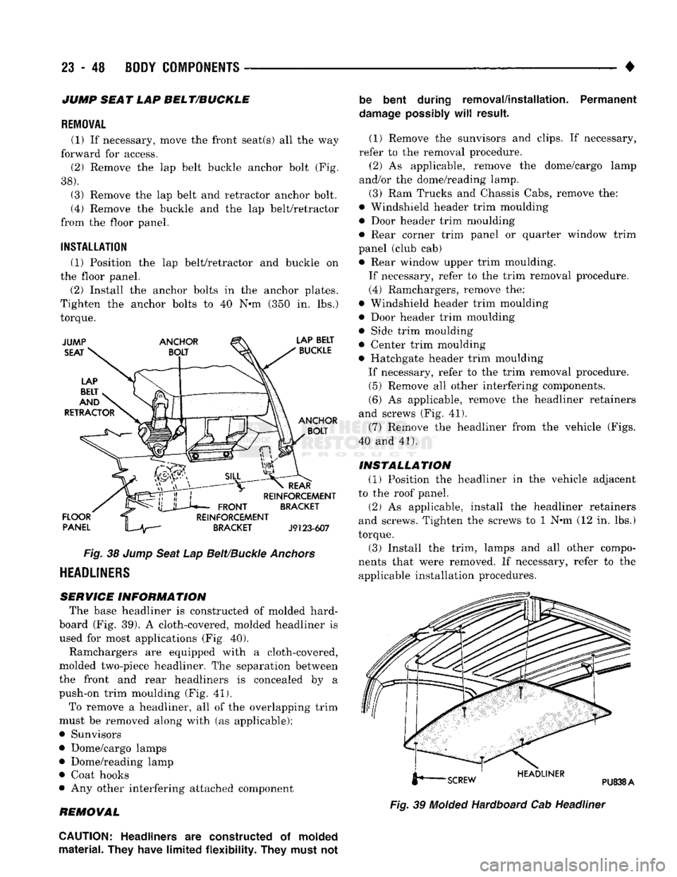
forward for access. (2) Remove the lap belt buckle anchor bolt (Fig.
38).
(3) Remove the lap belt and retractor anchor bolt.
(4) Remove the buckle and the lap belt/retractor
from the floor panel.
INSTALLATION
(1) Position the lap belt/retractor and buckle on
the floor panel.
(2) Install the anchor bolts in the anchor plates.
Tighten the anchor bolts to 40 N*m (350 in. lbs.)
torque.
Fig.
38
Jump
Seat
Lap
Belt/Buckle
Anchors
HEADLINERS
SERVICE INFORMATION
The base headliner is constructed of molded hard-
board (Fig. 39). A cloth-covered, molded headliner is
used for most applications (Fig, 40).
Ramchargers are equipped with a cloth-covered,
molded two-piece headliner. The separation between
the front and rear headliners is concealed by a
push-on trim moulding (Fig. 41).
To remove a headliner, all of the overlapping trim
must be removed along with (as applicable):
• Sunvisors
• Dome/cargo lamps • Dome/reading lamp
• Coat hooks
• Any other interfering attached component
REMOVAL be bent during removal/installation. Permanent
damage
possibly
will
result.
(1) Remove the sunvisors and clips. If necessary,
refer to the removal procedure. (2) As applicable, remove the dome/cargo lamp
and/or the dome/reading lamp.
(3) Ram Trucks and Chassis Cabs, remove the:
• Windshield header trim moulding
• Door header trim moulding
• Rear corner trim panel or quarter window trim
panel (club cab) • Rear window upper trim moulding.
If necessary, refer to the trim removal procedure.
(4) Ramchargers, remove the:
• Windshield header trim moulding
• Door header trim moulding
• Side trim moulding
• Center trim moulding
• Hatchgate header trim moulding
If necessary, refer to the trim removal procedure. (5) Remove all other interfering components.
(6) As applicable, remove the headliner retainers
and screws (Fig. 41).
(7) Remove the headliner from the vehicle (Figs.
40 and 41).
INSTALLATION
(1) Position the headliner in the vehicle adjacent
to the roof panel.
(2) As applicable, install the headliner retainers
and screws. Tighten the screws to 1 N*m (12 in. lbs.)
torque. (3) Install the trim, lamps and all other compo
nents that were removed. If necessary, refer to the applicable installation procedures.
Fig.
39
Molded
Hardboard Cab Headliner
CAUTION:
Headliners
are
constructed
of
molded
material. They have limited flexibility. They must
not
Page 1439 of 1502
24 - 2
HEATING
AND AIR
CONDITIONING
• housing is expelled through the molded rubber drain
tube into the engine compartment. The tube must be
kept open to prevent condensation from collecting in
the bottom of the housing.
The squeezed rubber flap at the drain tube tip is
designed to keep engine compartment air from enter ing into the system yet allow condensation to drain.
If the tip is not properly formed or has been dam
aged, the system will not drain properly. Therefore,
if the tube is damaged, it should be replaced.
• SERVICE VALVES—The service valves at the
compressor suction line and discharge tube are used
to test and service the refrigerant system. A special adapter (Tool C-4803) is required for performance
testing.
OPERATION The compressor increases the pressure and temper
ature of the refrigerant. The heated refrigerant vapor
is then pumped into the condenser where it cools by
giving off heat to air passing over the condenser fins.
As the refrigerant cools in the condenser, it con
denses into a liquid. Still under high pressure, the
liquid refrigerant passes into the receiver. The re
ceiver acts as a reservoir to furnish refrigerant to the
expansion (H) valve at all times. From the receiver,
the high pressure liquid refrigerant passes to the ex pansion (H) valve. The expansion (H) valve meters
refrigerant into the evaporator where a low pressure
is maintained by the suction side of the compressor.
As it enters the evaporator, the refrigerant immedi ately begins to boil by absorbing heat from the air
passing over the evaporator core. Having given up its
heat to boil the refrigerant, the air is cooled and
passes into the passenger compartment of the vehi
cle.
From the evaporator the vaporized refrigerant is
drawn back to the compressor to repeat the cycle. RADIATOR CAP
Air conditioned vehicles must be equipped with a
radiator cap having a holding pressure of 98-122 kPag (14-18 psig). Replace the radiator cap that does
not test within this specification.
CONDENSER Inspect the condenser for obstruction or foreign
matter. Clean if present.
Any obstruction to the free flow of air across the
condenser will decrease heat dissipation from the
condenser. This will in turn decrease the efficiency of
the condenser and decrease the evaporator's effi
ciency. These conditions result in increasing the dis
charge pressure and horsepower load on the engine.
The use of a bug screen is not recommended, it also
will decrease the free flow of air.
Inspect the condenser for bent or damaged fins.
The bent fins on the condenser deflect air flow and
decrease the condenser area.
BUG SCREENS Bug screens should NOT be installed on vehicles
equipped with air conditioning. A bug screen in
stalled in front of the condenser will reduce air flow
and air conditioner performance. Under severe heat
conditions a bug screen may cause the engine to
over-heat.
RESISTOR
BLOCK
The blower motor switch and resistor block, con
trols the speed of the blower motor. The resistor
block consists of 3 helical-wound wire resistors, con nected to terminals which are mechanically attached
to a phenolic board. This assembly is bolted to the
plenum.
The blower switch controls the blower motor speed
by selectively connecting in series one, two, three or none of the resistors to the blower motor.
Page 1445 of 1502
24 - 8
HEATING
AND AIR
CONDITIONING
• (e) If compressor clutch cycles 3 to 10 times per
minute with temperature between 20°C-32°C (68°F-
90°F),
the cycling switch is normal. If the compressor
clutch fails to engage, check for continuity in the elec
trical circuit. Above 32°C (90°F) the compressor clutch
may be continuously engaged (non-cycling) due to the
high heat load. This condition is normal.
(4)
Refer to the Evaporator Heater Assembly for
the Removal/Installation procedures.
TESTING
THE
SYSTEM
FOR
LEAKS
If the air conditioning system is not cooling properly,
check that the refrigerant system is fully charged with
R-12.
Follow the procedures in the Sight Glass Refrig
erant Level Test section of this group.
If the refrigerant system is empty or low in refrig
erant charge, a leak at any of the line fittings or
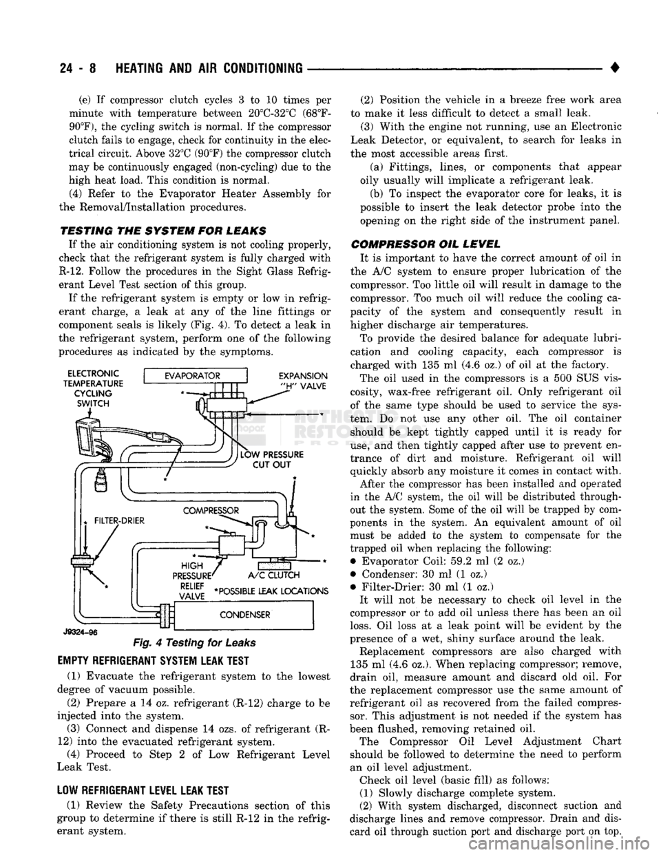
component seals is likely (Fig. 4). To detect a leak in
the refrigerant system, perform one of the following
procedures as indicated by the symptoms.
ELECTRONIC
TEMPERATURE CYCLING
SWITCH
EXPANSION
"H"
VALVE
J9324-96
Fig.
4 Testing for
Leaks
EMPTY REFRIGERANT SYSTEM LEAK TEST
(1) Evacuate the refrigerant system to the lowest
degree of vacuum possible.
(2) Prepare a 14 oz. refrigerant (R-12) charge to be
injected into the system. (3) Connect and dispense 14 ozs. of refrigerant (R-
12) into the evacuated refrigerant system, (4) Proceed to Step 2 of Low Refrigerant Level
Leak Test.
LOW REFRIGERANT LEVEL LEAK TEST
(1) Review the Safety Precautions section of this
group to determine if there is still R-12 in the refrig
erant system. (2) Position the vehicle in a breeze free work area
to make it less difficult to detect a small leak. (3) With the engine not running, use an Electronic
Leak Detector, or equivalent, to search for leaks in
the most accessible areas first.
(a) Fittings, lines, or components that appear
oily usually will implicate a refrigerant leak.
(b) To inspect the evaporator core for leaks, it is
possible to insert the leak detector probe into the opening on the right side of the instrument panel.
COMPRESSOR OIL LEVEL It is important to have the correct amount of oil in
the A/C system to ensure proper lubrication of the compressor. Too little oil will result in damage to the
compressor. Too much oil will reduce the cooling ca
pacity of the system and consequently result in
higher discharge air temperatures.
To provide the desired balance for adequate lubri
cation and cooling capacity, each compressor is
charged with 135 ml (4.6 oz.) of oil at the factory.
The oil used in the compressors is a 500 SUS vis
cosity, wax-free refrigerant oil. Only refrigerant oil of the same type should be used to service the sys
tem. Do not use any other oil. The oil container should be kept tightly capped until it is ready for
use,
and then tightly capped after use to prevent en
trance of dirt and moisture. Refrigerant oil will quickly absorb any moisture it comes in contact with.
After the compressor has been installed and operated
in the A/C system, the oil will be distributed through
out the system. Some of the oil will be trapped by com
ponents in the system. An equivalent amount of oil
must be added to the system to compensate for the
trapped oil when replacing the following: • Evaporator Coil: 59.2 ml (2 oz.)
• Condenser: 30 ml (1 oz.)
• Filter-Drier: 30 ml (1 oz.) It will not be necessary to check oil level in the
compressor or to add oil unless there has been an oil
loss.
Oil loss at a leak point will be evident by the
presence of a wet, shiny surface around the leak. Replacement compressors are also charged with
135 ml (4.6 oz.). When replacing compressor; remove,
drain oil, measure amount and discard old oil. For
the replacement compressor use the same amount of refrigerant oil as recovered from the failed compressor. This adjustment is not needed if the system has
been flushed, removing retained oil. The Compressor Oil Level Adjustment Chart
should be followed to determine the need to perform
an oil level adjustment. Check oil level (basic fill) as follows: (1) Slowly discharge complete system.
(2) With system discharged, disconnect suction and
discharge lines and remove compressor. Drain and dis card oil through suction port and discharge port on top.
Page 1447 of 1502
24 - 10
HEATING
AND AIR
CONDITIONING
•
(3) Add 50 ml (1.7 oz.) of clean refrigerant oil
through the suction port.
(4) Install compressor.
(5) Install the suction and discharge lines to the
compressor. Use new gaskets to prevent leakage.
Tighten the line nuts to 23 N*m (200 in. lbs.) torque.
(6)
Evacuate and charge system.
OVER-ALL
PERFORMANCE
TEST
Humidity has an important bearing on the temper
ature of the air delivered to the vehicle's interior.
This is true of all air conditioning systems It is im
portant to understand the effect humidity has on the
performance of the system. When humidity is high,
the evaporator has to perform a double duty. It must lower the air temperature and the temperature of the
moisture carried in the air. Condensing the moisture
in the air transfers a great deal of heat energy into
the evaporator fins and tubing. This reduces the amount of heat the evaporator can absorb from the
air.
Evaporator capacity used to reduce the amount of
moisture in the air is not wasted. Wringing some of
the moisture out of the air entering the vehicle adds
to the comfort of the passengers. However, an owner may expect too much from their air conditioning sys
tem on humid days. A performance test is the best
way to determine whether or not the system is per
forming up to standard. This test also provides valu able clues to the possible cause of trouble.
To perform the test the air temperature in the test
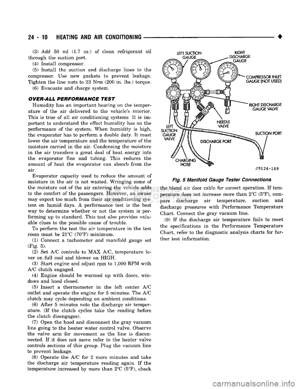
room must be 21°C (70°F) minimum. (1) Connect a tachometer and manifold gauge set
(Fig. 5).
(2) Set A/C controls to MAX A/C, temperature le
ver on full cool and blower on HIGH. (3) Start engine and adjust rpm to 1,000 RPM with
A/C clutch engaged.
(4) Engine should be warmed up with doors, win
dows and hood closed.
(5)
Insert a thermometer in the left center A/C
outlet and operate the engine for 5 minutes. The A/C
clutch may cycle depending on ambient conditions.
(6)
After 5 minutes note the discharge air temper
ature. (If the clutch cycles take the reading before
the clutch disengages).
(7) Open the hood and disconnect the gray vacuum
line going to the heater water control valve. Observe
the valve arm for movement as the line is discon nected. If it does not move refer to the heater valve
controls sections of this group. Plug the vacuum line
to prevent leakage.
(8) Operate the A/C for 2 more minutes and take
the discharge air temperature reading again. If the
temperature increased by more than 2°C (5°F), check
LEFT
SUCTION
RIGHT
J9124-109
Fig.
5 Manifold
Gauge
Tester
Connections
the blend air door cable for correct operation. If tem
perature does not increase more than 2°C
(5°F),
com
pare discharge air temperature, suction and discharge pressures with Performance Temperature Chart. Connect the gray vacuum line.
(9) If the discharge air temperature fails to meet
the specifications in the Performance Temperature Chart, refer to the diagnostic analysis charts for fur
ther test information.
Page 1456 of 1502
•
HEATING
AND
AIR
CONDITIONING
24 - 19
Connect
the
compound gauge hose
to the
compres
sor suction service valve gauge port (low-side).
Connect
the
high pressure gauge hose
to the
dis
charge service valve gauge port (high-side). Purge
air
from
the
high side test hose
by
opening
the high side hand valve
on the
manifold
for 3 to 5
seconds.
The
center connection
on the
manifold must
be open.
Purge
air
from
the low
side test hose
by
opening
the
low
side hand valve
on the
manifold
for 3 to 5
seconds.
The
center connection
on the
manifold must
be open.
The
air
conditioning system
may be
operated with
the gauge manifold assembly connected
in
this man
ner.
The
gauges will indicate respective operative
pressures.
DISCHARGING
THE SYSTEM
Since
the air
conditioning refrigerant system
is
pressurized,
it
will
be
necessary
to
completely dis charge
the
system before replacing
any
refrigerant
components.
The
procedure
is as
follows: (1) Install gauge
set as
described under manifold
gauge
set
installation. Make sure
the
gauge
set
valves
are
closed before attaching
the
hoses
to the re
frigerant system. (2) Install
a
long hose
to the
manifold gauge
set
connector.
Run
this hose
to the oil
collector
can
near
the shop exhaust system. A good
oil
collector
can may be
made from
a
large
empty coffee
can
with
a
plastic
top.
Slit
the
plastic
top
in the
form
of a Y to
make
an
entrance
for the
refrigerant hose
and
exit
for the gas.
(3) Open
the
compressor discharge
and
suction line
pressure valves
and
discharge
the
refrigerant into
the
oil
collector
can.
Watch
to
make sure
the
hose does
not
blow
out of the
collector
can.
(4) When
the
system
has
been completely dis
charged, measure
the
amount
of oil
collected
in the
can.
The
amount
of oil
measured should
be
added
to
the refrigerant system before
it is
charged. Discard
the used
oil. Add new oil.
EVACUATING
THE SYSTEM
Whenever
the
system
has
been opened
to the
atmo
sphere,
it is
absolutely essential that
the
system
be
evacuated
to
remove
all the air and
moisture.
Air in
the refrigerant system causes high compressor dis charge pressures,
a
loss
in
system performance,
and
oxidation
of the
compressor
oil
into
gum and
varnish.
Moisture
in the
refrigerant system
can
cause
the ex
pansion valve
to
malfunction. Under certain condi
tions
it can
react with
the
refrigerant
to
form destructive acids.
It is
necessary
to
adhere
to the
fol
lowing procedure
to
keep
air and
moisture
out of the
system. (1) Connect
the
manifold gauge
set to the
compres
sor
and
long test hose from manifold gauge
set
center
connection
to
Vacuum Pump Tool C-4289. (2) Open both manifold gauge
set
valves.
(3) Start
the
vacuum pump
and
operate until
the
evaporator suction gauge registers
at
least
-88
kPag (26 inches
of
vacuum).
If at
least
-88
kPag
(26
inches
of vacuum) cannot
be
obtained, either
the
system
has
a leak
or the
vacuum pump
is
defective. Check
the
vacuum pump.
If the
pump proves
to be
functioning
properly,
the
system
has a
leak. Charge
the
system
with
1
pound
of
refrigerant. Locate
and
repair
all
leaks.
Discharge
the
refrigerant
and
evacuate
the
system.
(4) Continue
to
operate
the
pump
for at
least
5
minutes.
(5) Close manifold valves. Turn
off the
vacuum
pump
and
observe evaporator suction gauge
for 2
minutes.
The
vacuum level should remain constant.
If
the
vacuum level falls
off, the
system
has a
leak. Charge
the
system with
450 g (1
pound)
of
refriger
ant. Locate
and
repair
all
leaks. Discharge
the
sys
tem
and
repeat evacuation procedure.
CHARGING
THE
SYSTEM
The refrigerant system must have been evacuated
using
the
previous procedure before charging. Charge
using only
R-12
refrigerant.
R-12 is
available
in
bulk
tanks
or 437 g (14 oz.)
cans. The special refrigerant dispensing manifold per
mits charging
3
cans
of
refrigerant
at a
time. When
using disposable cans
of
this type, carefully follow
the
can
manufacturers instructions.
WARNING: NEVER USE THESE CANS
TO
CHARGE
INTO
THE
HIGH
PRESSURE SIDE
OF
THE
SYSTEM
(COMPRESSOR
DISCHARGE PORT)
OR
INTO
A
SYSTEM
THAT
IS AT
HIGH
TEMPERATURE.
THE
HIGH
SYSTEM PRESSURES COULD
BE
TRANS
FERRED
INTO
THE
CHARGING
CAN
CAUSING
IT
TO EXPLODE.
Keep
the
refrigerant manifold valves capped when
not
in use.
Keep
a
supply
of
extra refrigerant-can-to
refrigerant-manifold gaskets
on
hand
so the
gaskets can
be
replaced periodically. This will insure
a
good
seal without excessive tightening
of the can or the
manifold nuts.
(1) Attach center hose from manifold gauge
set to
refrigerant dispensing manifold. Turn refrigerant manifold valves completely counterclockwise
so
they are fully open. Remove protective caps from refriger
ant manifold.
(2) Screw refrigerant cans into manifold.
Be
sure
manifold-to-can gasket
is in
place
and in
good condi
tion. Tighten
can and
manifold nuts
to 9.5 N»m (7 ft.
lbs.) torque.
Page 1457 of 1502
24
- 20
HEATING
AND AIR
CONDITIONING
• (3) Turn
3
refrigerant manifold valves completely
clockwise
to
puncture
the
cans
and
close
the
mani
fold valves.
(4) Purge
the air
from
the
charging line
by
loosen
ing
the
charging hose
at the
manifold gauge
set and
turn
one of the
refrigerant valves counterclockwise. When
the
refrigerant
gas
starts escaping from
the
loose connection, tighten
the
hose.
(5) Fully open
all 3
refrigerant manifold valves
and place
the
cans
of
refrigerant into
a pan
contain
ing 52°C (125°F) water.
The
water will warm
the
charging
can and aid in the
transfer
of the
charge
into
the
system.
(6) Start
the
engine
and
move
the
controls
to A/C
low blower position.
The electronic temperature cycling switch will pre
vent
the
clutch from engaging until refrigerant
is
added
to the
system.
If the
clutch does engage,
re
place
the
switch before proceeding
any
further. (7) Charge through
the
suction side
of the
system
by slowly opening
the
suction manifold valve. Adjust
the valve
as
necessary
so
charging pressure does
not
exceed
345
kPag
(50
psig). Maintain
the
temperature
of
the
water
in the pan by
adding warm water
as
necessary. (8) Adjust
the
engine speed
to a
fast idle
of
approx
imately
1,300 RPM.
(9) When
all 3
cans
of
refrigerant
are
completely
empty, close
the
manifold gauge
set
valves
and re
frigerant manifold valves. The maximum refrigerant charge
is 44 oz.
REFRIGERANT
LEAK REPAIR PROCEDURE
LOST CHARGE If
the
system
has
lost
all
charge
due to a
leak: (1) Evacuate
the
system.
(2) Charge
the
system with approximately
1
pound
of refrigerant. (3) Locate
all
leaks.
(4) Repair
all
leaks.
(5) Replace filter-drier bottle.
CAUTION:
Replacement
filter-drier
units
must
be
sealed
while
in
storage.
The
drier
used
in
these
units
absorbs
and
traps
moisture
quickly
upon
ex
posure
to the
atmosphere.
When
installing
a
drier,
have
all
tools
and
supplies ready
for
quick
reas
sembly
to
avoid keeping
the
system open
any
longer
than
necessary.
(6) Check system
oil
level. (7) Evacuate
and
charge
the
system.
LOW CHARGE If
the
system
has not
lost
all of its
refrigerant
charge; locate
and
repair
all
leaks.
If it is
necessary
to increase
the
system pressure
to
find
the
leak
(be
cause
of an
especially
low
charge),
add 230 g (1/2 lb)
of refrigerant.
If
there
has
been
a
significant
oil
loss,
check
the
system
oil
level.
If
leak repair
was
possible
without discharging system
and an oil
level check
was
not
necessary,
use
procedure
for
correcting
low
refrigerant level.
CORRECTING
LOW
REFRIGERANT LEVEL
Since
the
refrigeration system
is
completely sealed,
the refrigerant level will
not be low
unless there
is a
leak
in the
system. Before adding refrigerant where
the
cause
of a low
level
is not
known,
the
system should
be
tested
for
leaks.
Assuming that leaks have been corrected without
discharging
the
system, proceed with partial charge.
Install
and
connect manifold gauge
set.
(1) Close both manifold gauge
set
valves. Open
manifold gauge
set
needle valve.
(2) Connect
the
suction gauge test hose
to the
suc
tion service port
of the
compressor. Connect
the
dis charge gauge test hose
to the
discharge service port. (3) Connect
an end of
long test hose
to the
center
manifold outlet,
and
other
end to
refrigerant dispens ing manifold. (4) Close
the 2
dispensing manifold valves
and
open remaining dispensing manifold valve. Remove
protective
cap
from opened valve.
WARNING: NEVER
USE
THESE CANS
TO
CHARGE
INTO
THE
HIGH
PRESSURE SIDE
OF
THE
SYSTEM
(COMPRESSOR
DISCHARGE
PORT)
OR
INTO
A
SYSTEM
THAT
IS AT
HIGH
TEMPERATURE.
THE
HIGH
SYSTEM PRESSURES COULD
BE
TRANS
FERRED
INTO
THE
CHARGING
CAN
CAUSING
IT
TO EXPLODE.
(5) Screw
a can of R-12 to the
opened manifold
valve.
Be
sure gasket
is in
place
and in
good condi
tion. Tighten refrigerant
can and
manifold locking nut
to
ensure
a
good seal.
Do not
overtighten.
Tighten
to 9.5 N*m (7 ft. lbs.)
torque,
if
gasket
is in
good condition.
(6) Turn manifold valve (above
the
refrigerant
can)
completely clockwise
to
puncture
the can.
This closes
the valve
and
seals
the
refrigerant
in the can.
CAUTION:
Do not
heat refrigerant
12
above
52°C
(125°F).
(7) Place refrigerant
can in a
large
pan of
water
heated
to
52°C (125°F). Place
pan of
water containing
the refrigerant
can on an
accurate scale
so the
amount
of
refrigerant added
can be
weighed. Open
the refrigerant manifold valve.
(8) Purge
all air
from test hoses.
Air in the
system
will
be
trapped
in the
condenser causing abnormally
high discharge pressures
and
interfering with con densing
of the
refrigerant.
Page 1480 of 1502
EMISSION
CONTROL SYSTEMS
25 - :
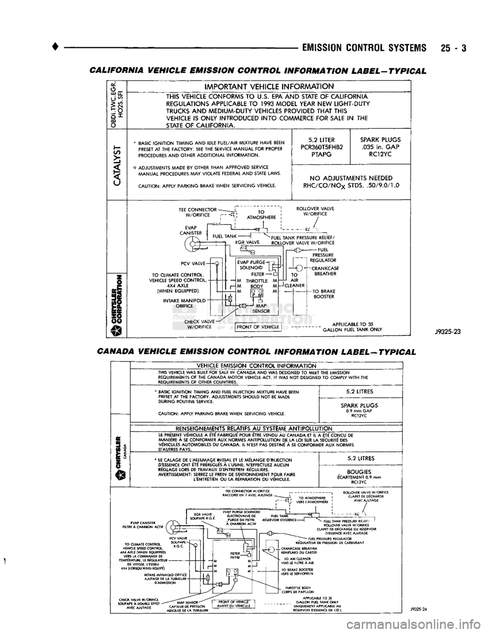
CALIFORNIA VEHICLE EMISSION CONTROL INFORMATION LABEL-TYPICAL
or,
o_ UJ
u_
U
^
>
CO
CQ
o
IMPORTANT
VEHICLE
INFORAAATION
THIS VEHICLE CONFORMS
TO
U.S.
EPA AND STATE
OF
CALIFORNIA REGULATIONS APPLICABLE
TO 1993
MODEL YEAR NEW
LIGHT-DUTY
TRUCKS
AND
MEDIUM-DUTY VEHICLES PROVIDED
THAT
THIS VEHICLE
IS
ONLY INTRODUCED
INTO
COMMERCE FOR
SALE
IN THE
STATE
OF
CALIFORNIA.
*
BASIC
IGNITION TIMING
AND
IDLE FUEL/AIR
MIXTURE HAVE BEEN
PRESET
AT THE
FACTORY.
SEE THE
SERVICE MANUAL
FOR
PROPER
PROCEDURES
AND
OTHER
ADDITIONAL
INFORMATION.
o
ADJUSTMENTS MADE
BY
OTHER
THAN
APPROVED
SERVICE MANUAL PROCEDURES
MAY
VIOLATE
FEDERAL
AND
STATE
LAWS.
CAUTION:
APPLY
PARKING BRAKE
WHEN
SERVICING
VEHICLE.
5.2
LITER
PCR360T5FHB2
PTAPG
SPARK
PLUGS
.035
in.
GAP RC12YC NO ADJUSTMENTS NEEDED
RHC/CO/NOx
STDS.
.50/9.0/1.0
TEE
CONNECTOR
W/ORIFICE
TO
ATMOSPHERE
ROLLOVER
VALVE
W/ORIFICE
/
PCV
VALVE-
TO
CLIMATE
CONTROL,
VEHICLE SPEED
CONTROL,
4X4
AXLE
(WHEN
EQUIPPED)
INTAKE
MANIFOLD"
ORIFICE
—
M
r-
M
EVAP
PURGE
SOLENOID
FILTER
THROTTLE
BODY
FUEL
TANK PRESSURE
RELIEF/
ROLLOVER
VALVE
W/ORIFICE
FUEL
PRESSURE
REGULATOR
1
r—O
O^-CRANKCASE
TO
AIR
CLEANER
APPLICABLE
TO
35
GALLON
FUEL
TANK
ONLY
J9325-23
CANADA VEHICLE EMISSION CONTROL INFORMATION LABEL-ATYPICAL
VEHICLE
EMISSION
CONTROL
INFORAAATION
THIS
VEHICLE
WAS
BUILT
FOR
SALE
IN
CANADA
AND WAS
DESIGNED
TO
MEET
THE
EMISSION
REQUIREMENTS
OF THE
CANADA
MOTOR
VEHICLE
ACT.
IT
WAS NOT
DESIGNED
TO
COMPLY
WITH
THE
REQUIREMENTS
OF
OTHER
COUNTRIES.
'
BASIC
IGNITION TIMING
AND
FUEL
INJECTION
MIXTURE HAVE BEEN
PRESET
AT
THE
FACTORY.
ADJUSTMENTS
SHOULD
NOT
BE
MADE
DURING
ROUTINE
SERVICE.
CAUTION:
APPLY
PARKING BRAKE
WHEN
SERVICING
VEHICLE.
5.2
LITRES
SPARK
PLUGS
0.9
mm GAP
RC12YC
RENSEIGNEMENTS RELATIFS
AU
SYSTEME
ANTIPOLLUTION
LE
PRESENT
VEHICULE
A
ETE
FABRIQUE'
POUR ETRE
VENDU
AU
CANADA
ET
IL
A
ETE
CONCU
DE
MANIERE
A
SE
CON
FORMER
AUX
NORMES
ANTIPOLLUTION
DE LA LOI SUR LA
SECURITE
DES
VEHICULES
AUTOMOBILES
DU
CANADA.
IL
N'EST
PAS
DESTINE'
A SE
CON
FORMER
AUX
NORMES
D'AUTRES
PAYS.
*
LE
CALAGE
DE
L'ALLUMAGE
INITIAL
ET LE
MELANGE
D'INJECTION
D'ESSENCE
ONT
ETC:
PREREGLE'S
A
L'USINE.
N'EFFECTUEZ
AUCUN
REGLAGE
LORS
DE
TRAVAUX
D'ENTRETIEN
REGULIERS.
AVERTISSEMENT:
SERREZ
LE
FREIN
DE
STATIONNEMENT
POUR
FAIRE
L'ENTRETIEN
OU
LA
RE'PARATION
DU
VEHICULE.
5.2
LITRES
,
BOUGIES
ECARTEMENT
0.9 mm
RC12YC
ROLLOVER VALVE W/ORIFICE CLAPET DE DECHARGE AVEC AJUTAGE EVAP PURGE SOLENOID
E'LECTROVALVE
DE
_
FUEL TANK PURGE
DU
FILTRE RESERVOIR
D'ESSENCE
-
A CHARBON ACTIF /
TO CLIMATE CONTROL,
VEHICLE SPEED CONTROL.
4X4 AXLE (WHEN EQUIPPED)
VERS LA COWMAN DE
DE
TEMPERATURE. LE REGULATEUR DE VITESSE, LESSIEU
4X4 (LORSQU'AINSI EQUIPE')
INTAKE MANIFOLD ORIFICE AJUTAGE DE LA TUBULURE D'ADMISSION FUEL TANK PRESSURE RELIEF/
I
ROLLOVER VALVE W/ORIFICE
CLAPET DE DECHARGE
DU
RESERVOIR D'ESSENCE AVEC AJUTAGE FUEL PRESSURE REGULATOR
REGULATEUR DE PRESSION DE CARBURANT CHECK VALVE W/ORIFICE
SOUPAPE
A
DOUBLE EFFET
-
AVEC AJUTAGE AAAP SENSOR
"
CAPTEUR DE PRESSION
ABSOLUE DE LA TUBULURE THROTTLE BODY
CORPS DE PAPILLON APPLICABLE
TO
35
GALLON FUEL TANK ONLY
UNIQUEMENT APPLICABLE
AU
RESERVOIR D'ESSENCE DE
132
L
Page 1483 of 1502
25
- 6
EMISSION CONTROL
SYSTEMS
•
EWAPORATIWE EMISSION CONTROLS
INDEX
page
Crankcase
Breather/Filter—Gas Powered
Engines
. . . 9
EVAP
(Evaporation)
Control
System
. 6
EVAP
Canister
. . 6
page
Evap
Canister
Purge
Solenoid
6
Fuel Tank
Filler
Tube
Cap . 7
Positive
Crankcase
Ventilation
(PCV)
System
.... 7
Pressure
Relief/Rollover Valve
6
EVAP (EVAPORATION) CONTROL SYSTEM GENERAL
INFORMATION
The function
of the
EVAP control system
is to
pre
vent
the
emissions
of
gasoline vapors from
the
fuel
tank into
the
atmosphere. When fuel evaporates
in
the fuel tank,
the
vapors pass through vent hoses
or
tubes
to a
carbon filled EVAP canister. They
are
temporarily held
in the
canister until they
can be
drawn into
the
intake manifold when
the
engine
is
running.
The vapors
are
drawn into
the
engine
at
idle
as
well
as off
idle. This system
is
called
a
Bi-level Purge
System where there
is a
dual source
of
vacuum
to re
move fuel vapor from
the
EVAP canister. The EVAP canister
is a
feature
on all
models
for
the storage
of
fuel vapors from
the
fuel tank.
The hoses used
in
this system
are
specially
manufactured.
If
replacement becomes neces sary,
it is
important
to use
only fuel resistant
hose.
PRESSURE
RELIEF/ROLLOVER VALVE
These vehicles
are
equipped with
a
combination
pressure relief
and
rollover valve. This dual function valve will relieve fuel tank pressure
and
also prevent
fuel flow through
the
fuel tank vent hoses
in the
event
of an
accidental vehicle rollover. The valve incorporates
a
pressure relief mechanism
that releases fuel tank pressure when
the
pressure increases above
the
calibrated sealing value. Refer
to
the Fuel Tank section
of
Group
14,
Fuel Systems
for
removal
and
installation procedures.
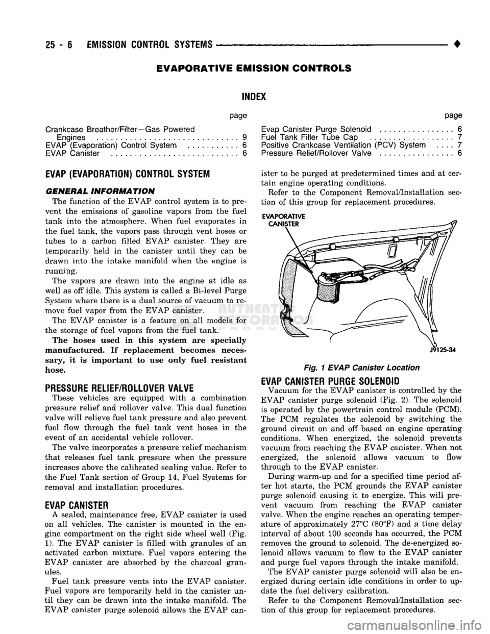
EVAP CANISTER
A sealed, maintenance free, EVAP canister
is
used
on
all
vehicles.
The
canister
is
mounted
in the en
gine compartment
on the
right side wheel well
(Fig.
1).
The
EVAP canister
is
filled with granules
of an
activated carbon mixture. Fuel vapors entering
the
EVAP canister
are
absorbed
by the
charcoal gran
ules.
Fuel tank pressure vents into
the
EVAP canister.
Fuel vapors
are
temporarily held
in the
canister
un
til they
can be
drawn into
the
intake manifold.
The
EVAP canister purge solenoid allows
the
EVAP can ister
to be
purged
at
predetermined times
and at
cer
tain engine operating conditions.
Refer
to the
Component Removal/Installation sec
tion
of
this group
for
replacement procedures.
EVAPORATIVE
Fig.
1
EVAP
Canister Location
EVAP CANISTER PURGE SOLENOID
Vacuum
for the
EVAP canister
is
controlled
by the
EVAP canister purge solenoid
(Fig. 2). The
solenoid
is operated
by the
powertrain control module (PCM).
The
PCM
regulates
the
solenoid
by
switching
the
ground circuit
on and off
based
on
engine operating conditions. When energized,
the
solenoid prevents
vacuum from reaching
the
EVAP canister. When
not
energized,
the
solenoid allows vacuum
to
flow
through
to the
EVAP canister. During warm-up
and for a
specified time period
af
ter
hot
starts,
the PCM
grounds
the
EVAP canister purge solenoid causing
it to
energize. This will pre
vent vacuum from reaching
the
EVAP canister
valve. When
the
engine reaches
an
operating temper ature
of
approximately 27°C (80°F)
and a
time delay
interval
of
about
100
seconds
has
occurred,
the PCM
removes
the
ground
to
solenoid.
The
de-energized
so
lenoid allows vacuum
to
flow
to the
EVAP canister and purge fuel vapors through
the
intake manifold. The EVAP canister purge solenoid will also
be en
ergized during certain idle conditions
in
order
to up
date
the
fuel delivery calibration. Refer
to the
Component Removal/Installation sec
tion
of
this group
for
replacement procedures.