diagram DODGE TRUCK 1993 Service Repair Manual
[x] Cancel search | Manufacturer: DODGE, Model Year: 1993, Model line: TRUCK, Model: DODGE TRUCK 1993Pages: 1502, PDF Size: 80.97 MB
Page 799 of 1502
13
- 12
FRAME AND BUMPERS
TO FRONT
END
WIRING
(SEE
SH
21)
T
T
18BK
18BK
YL* TO HEADLAMP
Jr
SWITCH -L2
14LG
TO FRONT
END
WIRING
(SEE
SH
22)
BLACK (RIGHT
SIDE
RADIATOR
YOKE
PANEL) BLACK
(RIGHT
' UPPER
SNOW
PLOW
FRAME)
BLACK
LEFT
AUXILIARY
PARK AND
TURN
SIGNAL LAMP
LEFT
AUXILIARY
HEADLAMP
RIGHT
AUXILIARY
HEADLAMP
RIGHT
AUXILIARY
PARK AND
TURN
SIGNAL LAMP
8901-2
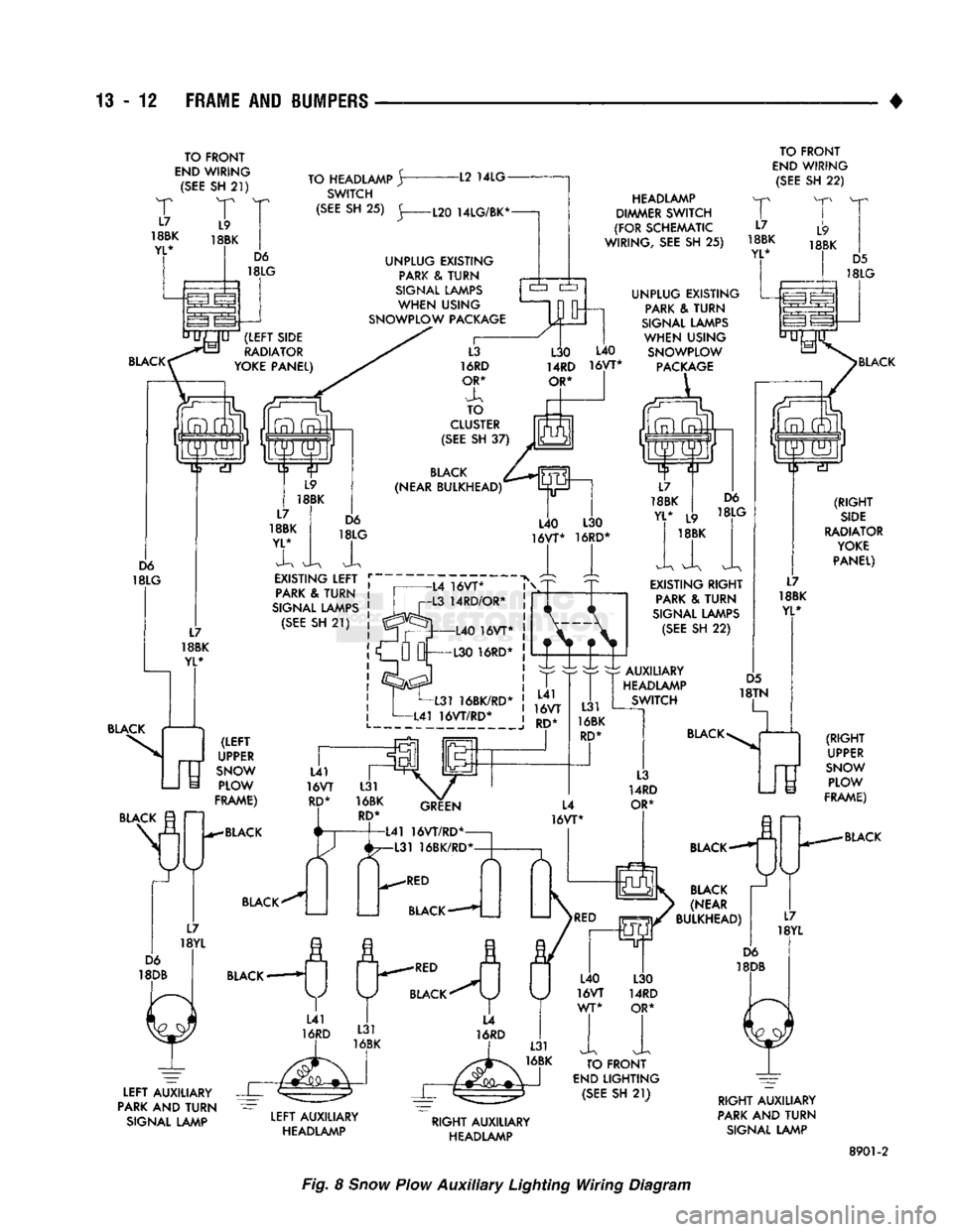
Fig. 8
Snow
Plow
Auxiliary
Lighting Wiring Diagram
Page 866 of 1502
•
FUEL SYSTEM 14-47 POWERTRAIN CONTROL MODULE (PCM)
60-WAY
CONNECTOR
Terminal identification and specific circuit applica
tions are shown in the PCM connector chart (Fig.
17).
Also refer to Group 8W, Wiring Diagrams.
SYSTEM
SCHEMATICS
Fuel system schematics for fuel injected engines
are shown in figures 18, 19 and 20.
Page 872 of 1502
•
FUEL
SYSTEM
14-53 ature sensor resistance chart. Replace the sensor if it
is not within the range of resistance specified in the chart. (3) Test the resistance of the wire harness. Do this
between the powertrain control module (PCM) wire
harness connector terminal 21 and the sensor connec tor terminal. Also check between terminal 4 to the sensor connector terminal. Repair the wire harness
as necessary if the resistance is greater than 1 ohm.
MANIFOLD
ABSOLUTE
PRESSURE
(MAP)
SENSOR
TEST
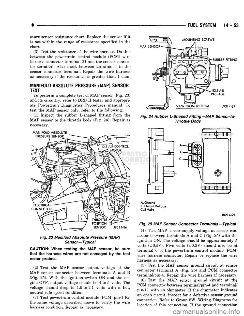
To perform a complete test of MAP sensor (Fig. 23)
and its circuitry, refer to DRB II tester and appropri
ate Powertrain Diagnostics Procedures manual. To
test the MAP sensor only, refer to the following: (1) Inspect the rubber L-shaped fitting from the
MAP sensor to the throttle body (Fig. 24). Repair as necessary.
MANIFOLD
ABSOLUTE
Fig.
23 Manifold
Absolute
Pressure
(MAP)
Sensor—
Typical
CAUTION:
When testing the MAP
sensor,
be
sure
that
the
harness
wires are not
damaged
by the test
meter
probes.
(2) Test the MAP sensor output voltage at the
MAP sensor connector between terminals A and B (Fig. 25). With the ignition switch ON and the en
gine OFF, output voltage should be 4-to-5 volts. The
voltage should drop to
1.5-to-2.1
volts with a hot,
neutral idle speed condition.
(3) Test powertrain control module (PCM) pin-1 for
the same voltage described above to verify the wire
harness condition. Repair as necessary.
Fig.
24
Rubber
L-Shaped
Fitting—MAP
Sensor-to-
Throttle
Body
A.
Ground
B.
Output Voltage
C.
5
Volts
J8914-91
Fig.
25 MAP
Sensor
Connector
Terminals—Typical
(4)
Test MAP sensor supply voltage at sensor con
nector between terminals A and C (Fig. 25) with the ignition ON. The voltage should be approximately 5
volts (±0.5V). Five volts (±0.5V) should also be at
terminal 6 of the powertrain control module (PCM)
wire harness connector. Repair or replace the wire
harness as necessary.
(5) Test the MAP sensor ground circuit at sensor
connector terminal A (Fig. 25) and PCM connector
terminal/pin-4. Repair the wire harness if necessary.
(6) Test the MAP sensor ground circuit at the
PCM connector between terminal/pin-4 and terminal/
pin-11 with an ohmmeter. If the ohmmeter indicates an open circuit, inspect for a defective sensor ground
connection. Refer to Group 8W, Wiring Diagrams for
location of this connection. If the ground connection
Page 876 of 1502
•
BOTTOM
VIEW
OF RELAY RELAY
CONNECTOR
DE-ENERGIZED
RELAY
ENERGIZED
RELAY
9214-157
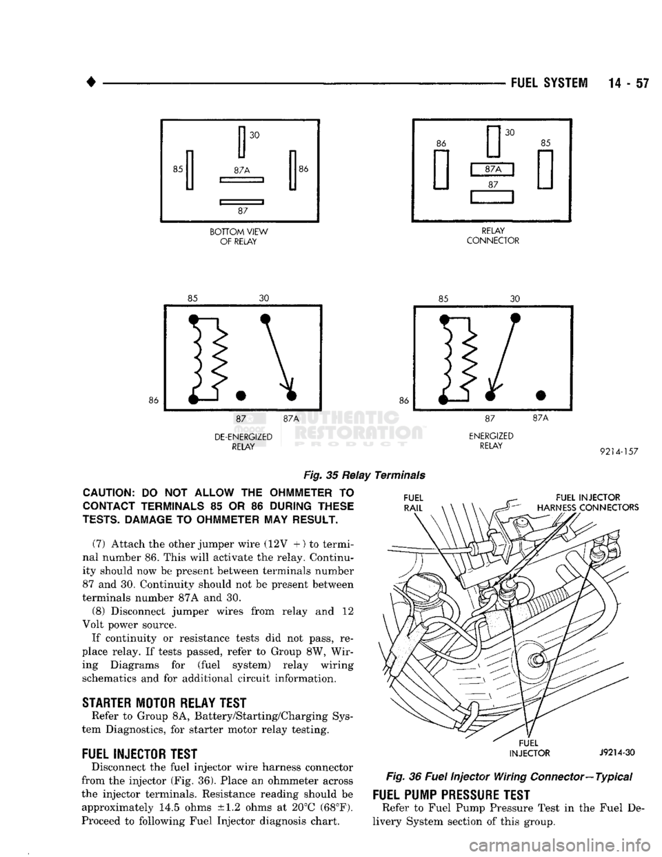
Fig.
35 Relay Terminals
CAUTION:
DO NOT
ALLOW
THE
OHMMETER
TO
CONTACT TERMINALS
85 OR 86
DURING THESE
TESTS.
DAMAGE
TO
OHMMETER
MAY
RESULT.
(7) Attach the other jumper wire (12V +) to termi
nal number 86. This will activate the relay. Continu
ity should now be present between terminals number
87 and 30. Continuity should not be present between
terminals number 87A and 30.
(8) Disconnect jumper wires from relay and 12
Volt power source.
If continuity or resistance tests did not pass, re
place relay. If tests passed, refer to Group 8W, Wir ing Diagrams for (fuel system) relay wiring schematics and for additional circuit information.
STARTER
MOTOR RELAY TEST
Refer to Group 8A, Battery/Starting/Charging Sys
tem Diagnostics, for starter motor relay testing.
FUEL INJECTOR TEST
Disconnect the fuel injector wire harness connector
from the injector (Fig. 36). Place an ohmmeter across
the injector terminals. Resistance reading should be approximately 14.5 ohms ±1.2 ohms at 20°C (68°F).
Proceed to following Fuel Injector diagnosis chart.
FUEL INJECTOR
HARNESS
CONNECTORS
FUEL
INJECTOR
J9214-30
Fig.
36
Fuel
Injector Wiring
Connector—
Typical
FUEL PUMP
PRESSURE
TEST
Refer to Fuel Pump Pressure Test in the Fuel De
livery System section of this group.
Page 1085 of 1502
21 - 84
AUTOMATIC TRANSMISSION-32RH/36RH/37RH/42RH/46RH
• The 3-4 timing valve is moved by line pressure
coming through the 3-4 shift valve. The timing valve
holds the 2-3 shift valve in an upshift position. The
purpose is to prevent the 2-3 valve from up or down shifting before the 3-4 valve. The 3-4 accumulator is mounted on the overdrive
housing. It performs the same function as the 2-3 ac cumulator. It is used to smooth engagement during
the 3-4 shift.
On models with a converter clutch, the clutch valve
applies the converter clutch when supplied with line
pressure through the converter clutch solenoid. The converter clutch solenoid is mounted on the
valve body. It is energized by an electrical signal
from the powertrain control module. Electronic con
trol of converter clutch engagement includes disen gagement at closed throttle during warmup and
during part throttle acceleration.
The switch valve directs apply fluid pressure to the
converter clutch in one position and releases it in the
opposite position. It also directs oil to the cooling and
lube circuits. The switch valve regulates oil pressure
to the torque converter by limiting maximum oil
pressure to 130 psi.
Boost
Valve Function The boost valve provides increased fluid apply pres
sure for converter clutch and overdrive clutch en
gagement.
The boost valve is connected to the overdrive clutch
circuit via a tube connected between the valve body
upper and lower housings. The valve is connected to
the converter clutch circuit via the regulator valve, switch valve and 3-4 shift and timing valves.
Hydraulic circuitry for the boost valve is shown in
the hydraulic flow diagrams. The diagrams are lo cated at the end of the transmission diagnosis and
test section.
During converter clutch engagement in fourth
gear, the valve supplies full line pressure directly to
the clutch. The increased pressure available at the clutch provides smooth shifting and positive engage
ment. The 3-4 upshift causes the boost valve to increase
line pressure to the overdrive clutch. Pressure also
increases with throttle opening. This ensures positive
clutch engagement during periods of high throttle
opening acceleration.
Converter
Clutch
Control The converter clutch valve applies the converter
clutch when supplied with line pressure through the
converter clutch solenoid. The solenoid is mounted on
the valve body and energized by an electrical signal
from the powertrain control module. Electronic con
trol of converter clutch operation includes clutch re lease at closed throttle during warmup and during
part throttle acceleration. The boost valve provides additional apply pressure for converter clutch appli
cation.
The switch valve directs fluid apply pressure to the
converter clutch in one position and releases it in the
opposite position. It also directs oil to the cooling and lube circuits. The switch valve regulates oil pressure
to the torque converter by limiting maximum oil
pressure to 130 psi.
Clutch/Band
Application The clutch and servo pistons are actuated by line
pressure. When fluid pressure is released, the pistons are released by spring pressure.
On 2-3 upshifts, the front servo piston is released
by spring tension and hydraulic pressure. The accu mulator controls hydraulic pressure on the apply side of the front servo during 1-2 upshifts and all throttle
openings.
The overdrive direct clutch is applied by spring
pressure. The direct clutch is applied in all ranges except fourth gear.
The overdrive clutch is applied in fourth gear only.
The clutch is applied by the overdrive piston which is actuated by line pressure through the 3-4 shift valve.
Page 1086 of 1502
•
AUTOMATIC TRANSiISSiOi-32RH/38RH/37RH/42RH/4eRH
21 - 81 AUTOMATIC TRANSMISSION DIAGNOSIS AND TESTING
INDEX
page
Air Testing Clutch
and
Band Operation
91
Analyzing
the
Road Test
87
Converter Housing Fluid Leak Diagnosis
.......
92
Converter
Stall
Test
90
Diagnosis
Charts
and
Hydraulic Flow Diagrams
. . 95
Fluid Contamination
86
Fluid Level
and
Condition
85
GENERAL
INFORMATION
The diagnosis
and
testing information
in
this sec
tion applies
to
three
and
four speed models alike.
Di
agnosis
and
test procedures apply
to all
models
except where indicated. Diagnosis information that
only applies
to
42RH/46RH models
is
noted.
Automatic transmission problems
can be a
result
of
poor engine performance, incorrect fluid level, incor
rect linkage adjustment, band
or
hydraulic control
pressure adjustments, hydraulic system malfunctions
or electrical/mechanical component malfunctions.
Begin diagnosis
by
checking
the
easily accessible
items such
as:
fluid level
and
condition, linkage
ad
justments
and
electrical connections
on
4-speed mod
els.
A
road test will determine
if
further diagnosis
is
necessary. Procedures outlined
in
this section should
be
per
formed
in the
following sequence
to
realize
the
most accurate results:
• Preliminary diagnosis
• Fluid Level
and
condition • Linkage Adjustment
• Road test
• Hydraulic pressure test • Stall test
•
Air
pressure tests
• Leak Tests
• Analyze test results
and
consult diagnosis charts
PRELIMINARY
DIAGNOSIS
Two basic procedures
are
required.
One
procedure
for vehicles that
are
driveable
and an
alternate pro cedure
for
disabled vehicles (will
not
back
up or
move forward).
Vehicle
Is
Driveable
(1) Check fluid level
and
condition.
(2) Adjust throttle
and
gearshift linkage
if
com
plaint
was
based
on
delayed, erratic,
or
harsh shifts.
(3)
On
4-speed models, check electrical connections
at dash switch
and
transmission case. Turn control
switch
to ON
position before proceeding. (4) Road test
and
note transmission operating
characteristics.
page
Gearshift Linkage
87
General
Information
85
Hydraulic Pressure Test
88
Overdrive Fourth Gear
Electrical
Controls
......
86
Preliminary Diagnosis
85
Road
Test
87
Throttle
Valve Cable
86
(a)
If
acceleration
is
sluggish,
or if
abnormal
throttle opening
is
needed
to
maintain normal speeds with
a
properly tuned engine, perform
a
stall test
to
check converter clutch operation. (b)
On
42RH/46RH,
if
fourth gear upshift does
not occur, check overdrive solenoid
and
switch wir ing
for
opens, shorts, grounds.
(c)
If
slippage
and
engine flare
is
noted, perform
hydraulic pressure test
and air
pressure test
to
check clutch-band-governor operation.
Vehicle
Is
Disabled
(1) Check fluid level
and
condition.
(2) Check
for
broken, disconnected throttle link
age.
(3) Check
for
cracked, leaking cooler lines,
or
loose, missing pressure port plugs.
(4) Raise vehicle, start engine, shift transmission
into gear
and
note following:
(a)
If
propeller shafts turn
but
wheels
do not,
problem
is
with differential
or
axle shafts. (b)
If
propeller shafts
do not
turn
and
transmis
sion
is
noisy, stop engine. Remove
oil pan, and
check
for
debris.
If pan is
clear, remove transmis
sion
and
check
for
damaged drive plate, converter,
oil pump
or
input shaft.
(c)
If
propeller shafts
do not
turn
and
transmis
sion
is not
noisy, perform hydraulic pressure test
to
deter
mine
if
problem
is a
hydraulic
or
mechanical.
FLUID LEVEL AND CONDITION
(1) Place vehicle
on
level surface. This
is
impor
tant
for an
accurate reading. (2)
Do not
check level until fluid
is at
normal
op
erating temperature
of
approximately 82°C (180°F).
This
is
necessary
to
avoid false readings which could
produce under
or
over fill condition, (3) Fully apply parking brakes.
(4) Start
and run
engine
at
curb idle speed. Then
shift transmission through
all
gear ranges
and
back
to Neutral. (5) Clean
top of
filler tube
and
dipstick
to
keep dirt
out
of
tube.
Page 1096 of 1502
•
AUTOMATIC
TRANSMISSION—32RH/36RH/37RH/42RH/46RH
21 - ii
DIAGNOSIS
CHARTS AND HYDRAULIC
FLOW
DIAGRAMS
The diagnosis charts and hydraulic flow diagrams
provide additional reference for transmission diagno
sis.
The diagnosis charts provide general information
on a variety of transmission, overdrive unit and con
verter clutch fault conditions. The Transmission Unit diagnosis charts apply to all transmission models.
The Overdrive Unit charts apply to the four speed
transmissions only.
The hydraulic flow diagrams outline transmission
fluid flow and hydraulic circuitry. The flow diagrams also provide basic working pressures for the various
gear ranges.
Page 1448 of 1502

HEATING
AND
AIR
CONDITIONING
24 -
TEMPERATURE
IN
TEST AREA
21-29° C
(70-85°
F)
VERIFY R-12 CHARGE-CONNECT MANIFOLD GAUGES
SEE
MAINTENANCE AND ADJUSTMENTS SECTION
IF
R-12
CHARGE
IS
LOW, CORRECT LEAK, EVACUATE, AND CHARGE SYSTEM
BYPASS
CYCLING CLUTCH SWITCH USING JUMPER WIRE REFER
TO
GROUP
8W,
WIRING DIAGRAMS
START ENGINE ADJUST IDLE
TO 1000
rpm
IN
PARK OR NEUTRAL
WITH
PARK BRAKE SET LOCATE AND REMOVE BOTH
VACUUM LINES AT RECIRC DOOR ACTUATOR INSTALL
LT-GN LINE WHERE DK-GN LINE HAD BEEN
CLOSE
PASSENGER COMPARTMENT
SET
CONTROL TO A/C, PANEL, HIGH BLOWER, FULL HEAT
ENGINE
RPM BLOWER
MOTOR
SPEED
I
EVAPORATOR
I
SUCTION GAUGE
I
PSIG
(kPag)
1
COMPRESSOR
DISCHARGE
GAUGE
PSIG
(kPag)
2
—m
POSSIBLE
I
CAUSE
I
20-35
PSIG
140-240
PSIG
1000 —
HI
(140 TO 240
kPag)
(966
TO
1656
kPag)
i
— NORMAL
Cr a
FREEZE
H-VALVE 15 INCHES
OF VACUUM
THAW
H-VALVE 38 PSIG
(262
kPag)
OR MORE THEN
DROPS
TO 25 TO 35
PSIG
(172
TO
240
kPag)
RETURN RECIRC DOOR VACUUM LINES
TO
NORMAL a
1000
HI
20 30
PSIG
(140 TO 207
kPag)
H240
PSIG OR HIGHER
(1656
kPag)
20-30
PSIG
(140-207
kPag)
140
PSIG
(966
kPag)
OR
LESS
H-VALVE
STUCK OPEN
IF
CONDITIONS
CANNOT BE MET
H-VALVE
STUCK CLOSED
IF
CONDITIONS
CANNOT BE MET
RESTRICTED
CONDENSER-
RESTRICTED
DISCHARGE
LINE
-RADIATOR
OVERHEATING-
AIR
IN
SYSTEM- OVERCHARGED
SYSTEM-COOLING FAN INOP.
RECONNECT LOW PRESSURE/CYCLING SWITCH AND RECONNECT THE VACUUM LINES
TO
THE RECIRC/ACUATOR DEFECTIVE
COMPRESSOR
HEAD
GASKET
OR
DISCHARGE
REEDS
J9124-104
AIR
CONDITIONING REFRIGERANT SYSTEM DIAGNOSIS
Page 1501 of 1502
CLUSTER
AND
GAUGE SERVICE PROCEDURES
. . . 8E-12
CLUSTER
AND
GAUGE TEST PROCEDURES
8E-5
GENERAL INFORMATION
8E-1
MESSAGE
CENTER-DIESEL ENGINE
8E-4
MESSAGE
CENTER-GAS ENGINE
8E-3
SWITCH
AND
PANEL COMPONENT SERVICE
8E-16
INTRODUCTION
lntro.-1
DESIGNATIONS, LABELS/PLATES/DECALS, CODES AND DIMENSIONS/WEIGHTS
Intro.-1
MEASUREMENT
AND
TORQUE SPECIFICATIONS
lntro.-11
LAMPS
8L-1
BULB APPLICATION
8L-11
EXTERIOR LAMPS
8L-1
EXTERIOR LAMPS SERVICE PROCEDURES
8L-3
INTERIOR LAMPS
8L-10
LUBRICATION
AND
MAINTENANCE
0-1
CHASSIS
AND
BODY
0-28
DRIVETRAIN
0-22
ENGINE MAINTENANCE
0-14
GENERAL INFORMATION
0-1
POWER DOOR LOCKS
8P-1
SERVICE
PROCEDURES
8P-2
TEST PROCEDURES
8P-1
POWER MIRRORS
8T-1
SERVICE
PROCEDURES
8T-2
TEST PROCEDURES
8T-1
POWER WINDOWS
8S-1
SERVICE
PROCEDURES
8S-3
TEST PROCEDURES
8S-1
PROPELLER SHAFTS
16-1
GENERAL INFORMATION
16-1
PROPELLER SHAFT REPLACEMENT
16-8
SERVICE
DIAGNOSIS/PROCEDURES
16-3
TORQUE SPECIFICATIONS
16-15
UNIVERSAL
JOINT
REPLACEMENT
16-10
REAR
SUSPENSION
AND
AXLE
3-1
8
3/8 and 9 1/4
AXLE
3-11
GENERAL INFORMATION
3-1
MODEL
60 and 70
AXLES
3-29
POWER-LOK DIFFERENTIAL
3-55
REAR
SUSPENSION—2WD
and 4WD
VEHICLES
.... 3-3
SERVICE
DIAGNOSIS
3-6
SPECIFICATIONS
3-27
SURE-GRIP
DIFFERENTIAL SERVICE
3-28
TORQUE SPECIFICATIONS
3-59
TRAC-LOK DIFFERENTIAL
3-51
REAR
WINDOW DEFOGGER
8N-1
REPAIR PROCEDURES (GRID LINES, TERMINALS,
AND PIGTAILS)
8N-3
SERVICE
PROCEDURES
8N-4
TEST PROCEDURES
8N-1
STEERING
19-1
GENERAL INFORMATION
19-1
POWER STEERING PUMP
19-11
POWER STEERING SYSTEM DIAGNOSIS
19-2
RECIRCULATING BALL POWER STEERING GEAR
. . 19-20
STEERING COLUMN
19-35
STEERING LINKAGE
19-17
TORQUE SPECIFICATIONS
19-40
TRANSMISSION
AND
TRANSFER CASE
21-1
AUTOMATIC TRANSMISSION DIAGNOSIS
AND
TESTING
21-85
AUTOMATIC TRANSMISSION REMOVAL
AND
INSTALLATION
21-142
AUTOMATIC TRANSMISSION—32RH/36RH/37RH/
42RH/46RH
21-73
G360
MANUAL TRANSMISSION
21-46
G360
TRANSMISSION OVERHAUL
21-53
GENERAL INFORMATION-32RH/36RH/37RH
21-73
GENERAL INFORMATION—42RH/46RH
. . . 21-78
IN-VEHICLE SERVICE—32RH/36RH/37RH/ 42RH/46RH
21-130
NP205
TRANSFER CASE
21-342
NP241
TRANSFER CASE
21-350
NV4500
MANUAL TRANSMISSION
21-1
NV4500
TRANSMISSION OVERHAUL
21-6
OVERDRIVE
UNIT
OVERHAUL—42RH/46RH
21-324
TRANSMISSION OVERHAUL—32RH
21-152
TRANSMISSION OVERHAUL—36RH/37RH
21-192
TRANSMISSION OVERHAUL—42RH
21-233
TRANSMISSION OVERHAUL—46RH
21-278
TRANSMISSION/TRANSFER CASE SPECIFICATIONS
21-364
TURN SIGNALS
AND
HAZARD WARNING FLASHER
. . . 8J-1
GENERAL INFORMATION
8J-1
MULTIFUNCTION SWITCH SERVICE PROCEDURES.
. 8J-3
MULTIFUNCTION SWITCH TESTING PROCEDURES.
. 8J-2
VEHICLE
SPEED
CONTROL SYSTEM
8H-1
SERVICE
PROCEDURES
8H-11
TEST PROCEDURES
8H-7
WHEELS
AND
TIRES
22-1
TIRES
22-1
TORQUE SPECIFICATIONS
22-13
VEHICLE VIBRATION
22-11
WHEELS
22-6
WINDSHIELD WIPER
AND
WASHER
SYSTEMS
8K-1
INTERMITTENT WINDSHIELD WIPER FUNCTION
AND
SWITCH TESTING PROCEDURES
8K-6
TWO
SPEED
WINDSHIELD WIPER MOTOR
AND
SWITCH TESTING PROCEDURES
8K-1
WINDSHIELD WASHERS
8K-10
WINDSHIELD WIPER SYSTEM SERVICE
PROCEDURES
8K-7
WIRING DIAGRAMS
8W-1
COMPONENT IDENTIFICATION
8W-9
GENERAL INFORMATION
8W-1
SPLICE
LOCATIONS
8W-29
WIRING DIAGRAMS AD-BODY
8W-37