fuel DODGE TRUCK 1993 Service User Guide
[x] Cancel search | Manufacturer: DODGE, Model Year: 1993, Model line: TRUCK, Model: DODGE TRUCK 1993Pages: 1502, PDF Size: 80.97 MB
Page 34 of 1502
•
LUBRICATION
AND
MAINTENANCE
0 - 15
DIESEL
ENGINES
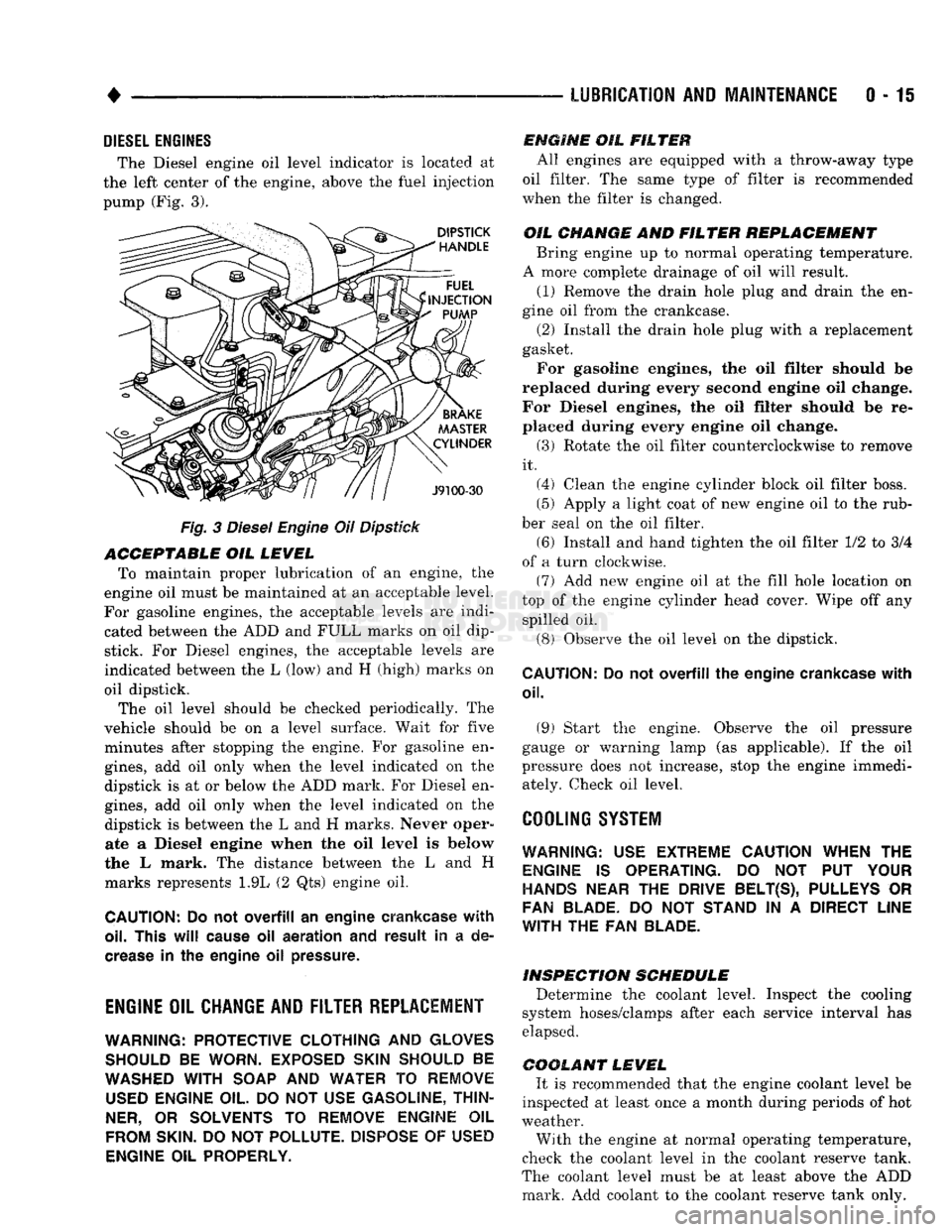
The Diesel engine oil level indicator is located at
the left center of the engine, above the
fuel
injection
pump (Fig. 3).
Fig.
3
Diesel
Engine
Oil
Dipstick
ACCEPTABLE
OIL
LEVEL
To maintain proper lubrication of an engine, the
engine oil must be maintained at an acceptable level.
For gasoline engines, the acceptable levels are indi cated between the ADD and
FULL
marks on oil
dip
stick. For Diesel engines, the acceptable levels are
indicated between the L (low) and H
(high) marks
on
oil dipstick. The oil level should be checked periodically. The
vehicle should be on a level surface. Wait for
five
minutes after stopping the engine. For gasoline en
gines,
add oil only when the level indicated on the
dipstick is at or below the ADD mark. For Diesel en
gines,
add oil only when the level indicated on the
dipstick is between the L and H marks.
Never oper
ate a Diesel
engine when
the oil
level
is below
the L mark. The distance between the L and H
marks represents 1.9L (2 Qts) engine oil.
CAUTION:
Do not
overfill
an
engine crankcase
with
oil. This
will
cause
oil
aeration
and
result
in a de
crease
in the
engine
oil
pressure.
ENGINE
OIL
CHANGE AND FILTER REPLACEMENT
WARNING: PROTECTIVE CLOTHING
AND
GLOVES SHOULD
BE
WORN. EXPOSED SKIN SHOULD
BE
WASHED
WITH
SOAP
AND
WATER
TO
REMOVE
USED
ENGINE
OIL.
DO NOT
USE
GASOLINE, THIN
NER,
OR
SOLVENTS
TO
REMOVE ENGINE
OIL
FROM
SKIN.
DO NOT
POLLUTE. DISPOSE
OF
USED
ENGINE
OIL
PROPERLY.
ENGINE
OIL
FILTER
All engines are equipped with a throw-away type
oil filter. The same type of filter is recommended
when the filter is changed.
OIL CHANGE
AND
FILTER
REPLACEMENT
Bring engine up to normal operating temperature.
A more complete drainage of oil will result.
(1) Remove the drain hole plug and drain the en
gine oil from the crankcase.
(2) Install the drain hole plug with a replacement
gasket. For gasoline engines, the oil filter should be
replaced during every second engine oil change.
For Diesel engines, the oil filter should be re
placed during every engine oil change.
(3) Rotate the oil filter counterclockwise to remove
it.
(4) Clean the engine cylinder block oil filter boss. (5) Apply a light coat of new engine oil to the rub
ber seal on the oil filter.
(6) Install and hand tighten the oil filter 1/2 to 3/4
of a turn clockwise. (7) Add new engine oil at the fill hole location on
top of the engine cylinder head cover. Wipe off any spilled oil.
(8) Observe the oil level on the dipstick.
CAUTION:
Do not
overfill
the
engine crankcase
with
oil.
(9)
Start the engine. Observe the oil pressure
gauge or warning lamp (as applicable). If the oil
pressure does not increase, stop the engine immedi ately. Check oil level.
COOLING SYSTEM
WARNING:
USE
EXTREME CAUTION WHEN
THE
ENGINE
IS
OPERATING.
DO NOT PUT
YOUR
HANDS NEAR
THE
DRIVE BELT(S), PULLEYS
OR
FAN BLADE.
DO NOT
STAND
IN A
DIRECT LINE
WITH
THE FAN
BLADE.
INSPECTION SCHEDULE
Determine the coolant level. Inspect the cooling
system hoses/clamps after each service interval has
elapsed.
COOLANT LEVEL
It is recommended that the engine coolant level be
inspected at least once a month during periods of hot
weather.
With the engine at normal operating temperature,
check the coolant level in the coolant reserve tank.
The coolant level must be at least above the ADD mark. Add coolant to the coolant reserve tank only.
Page 37 of 1502
0-18
LUBRICATION
AND
MAINTENANCE
• MAINTENANCE SCHEDULE
A crankcase ventilation system must be clean to
provide good operation and durability. Periodic main
tenance is necessary. Replace the PCV valve. Re
move residual combustion deposits from the hoses and throttle body/intake manifold passages.
The PCV valve should be replaced and the system
should be serviced at the interval specified in main
tenance schedule. If a vehicle is routinely used for short trips, the crankcase ventilation system could
possibly require more maintenance.
CRANKCASE AIR INLET FILTER
MAINTENANCE SCHEDULE Replace or clean, the air inlet filter at the interval
specified in maintenance schedule.
More frequent PCV system maintenance could be
required for:
• Vehicles routinely used for short trips
• Vehicles routinely involved in stop and go traffic
operation
• Vehicles routinely involved in extended periods of
engine idle
MAINTENANCE Clean and lubricate the crankcase air inlet filter
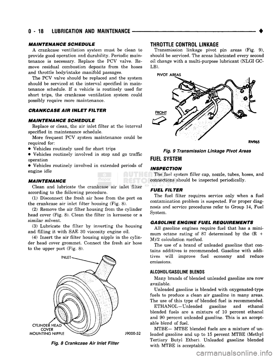
according to the following procedure. (1) Disconnect the fresh air hose from the port on
the crankcase air inlet filter housing (Fig. 8).
(2) Remove the air filter housing from the cylinder
head cover (Fig. 8). Clean the filter in kerosene or a similar solvent.
(3) Lubricate the filter by inverting the housing
and filling it with SAE 30 viscosity engine oil.
(4) Insert the air filter housing nipple in the cylin
der head cover grommet. Connect the fresh air hose
to the upper port (Fig. 8).
J9000-52
Fig.
8
Crankcase
Air Inlet
Filter
THROTTLE CONTROL LINKAGE
Transmission linkage pivot pin areas (Fig. 9),
should be serviced. The areas lubricated every second
oil change with a multi-purpose lubricant (NLGI GC-
LB).
PIVOT
AREAS
Fig.
9
Transmission
Linkage
Pivot Areas
FUEL
SYSTEM
INSPECTION The fuel system filler cap, nozzle, tubes, hoses, and
connections should be inspected periodically.
FUEL FILTER The fuel filter requires service only when a fuel
contamination problem is suspected. For proper diag
nosis and service procedures refer to Group 14, Fuel
System.
GASOLINE ENGINE FUEL REQUIREMENTS All gasoline engines require fuel that has a mini
mum octane rating of 87 determined by the (R +
M)/2 calculation method.
The use of a brand of unleaded gasoline that con
tains additives is recommended. Gasoline with addi
tives will improve fuel economy and reduce emissions.
ALCOHOL/GASOLINE
BLENDS
Many brands of blended unleaded gasoline am now
available. Unleaded gasoline is blended with oxygenated-type
fuels to produce a clean air gasoline in many areas.
The use of this type of blended fuel is recommended.
ETH ANOL—Unleaded gasoline and ethanol
blended fuels are a mixture of 10 percent ethanol and 90 percent unleaded gasoline. This is an accept
able blend of fuel.
MTBE— MTBE blended fuels are a mixture of un
leaded gasoline and up to 15 percent MTBE (Methyl
Tertiary Butyl Ether). Unleaded gasoline blended
with MTBE is acceptable.
Page 38 of 1502
•
LUBRICATION
AND
MAINTENANCE
0 - 19 ETBE— This fuel is a mixture of unleaded gasoline
and up to 17 percent ETBE (Ethyl Tertiary Butyl
Ether).
Unleaded gasoline blended with ETBE is ac ceptable.
METHANOL—Do not use unleaded gasoline
blended with methanol. The use of this type of alco hol can result in engine performance and damage to
critical components. Engine problems that result
from the use of methanol possibly will not be covered by the new vehicle warranty.
Certain brands of unleaded gasoline contain a per
centage of unidentified alcohol. These types of un
leaded gasoline are not recommended.
ADDITIVES MIXED
WITH
GASOLINE
Use of fuel system cleaning additives should be
avoided. Many of these solutions could contain highly
active solvents. This type of solvent can be harmful
to the gasket and diaphragm material within the fuel system.
DIESEL
ENGINE FUEL REQUIREMENTS
All Diesel engines normally can use number 2D
Diesel fuel for most year-round operations. A fuel
conforming to ASTM Specification D-975 is recom
mended. For extreme cold-weather operation (below
-18°C/0°F), or for prolonged cold-climate operation ei
ther:
• Use No. ID fuel, or
• Add an equal quantity of kerosene to No. 2D fuel (a 50/50 mixture).
Both methods provide protection against fuel gel
ling and waxing.
Diesel fuel seldom is without water contamination.
To help prevent fuel system malfunctions, drain all accumulated water from the separators periodically.
VACUUM OPERATED,
EMISSION
CONTROL
COMPONENTS
MAINTENANCE SCHEDULE
The following emission controls should be replaced
at the interval specified in the maintenance sched
ule:
• Bi-level purge check valves
• Delay valves
• Heated air temperature sensor (HATS)
• Air cleaner vacuum motors
EXHAUST
GAS RECIRCULATION (EGR)
SYSTEM
MAINTENANCE SCHEDULE
Replace the EGR valve and tube, and clean the
passages at the interval specified in maintenance schedule. If necessary, refer to Group 25—Emission
Control Systems for additional information.
OXYGEN
(02)
SENSOR
MAINTENANCE SCHEDULE
Replace the 02 sensor at the interval specified in
maintenance schedule.
IGNITION
CABLES,
DISTRIBUTOR CAP AND
ROTOR
MAINTENANCE SCHEDULE
Replace the ignition cables, distributor cap, and ro
tor at the interval specified in maintenance schedule.
Inspect the distributor for excessive wear and re
place, as necessary. Refer to Group 8D—Ignition Sys
tems for additional information.
IGNITION TIMING
MAINTENANCE SCHEDULE
Test and adjust, if necessary, the ignition timing at
the interval specified in maintenance schedule. Refer
to the specifications listed on the engine Emission Control Information label. Refer to Group 8D—Igni
tion Systems and to Group 25—Emission Control Systems for additional service information.
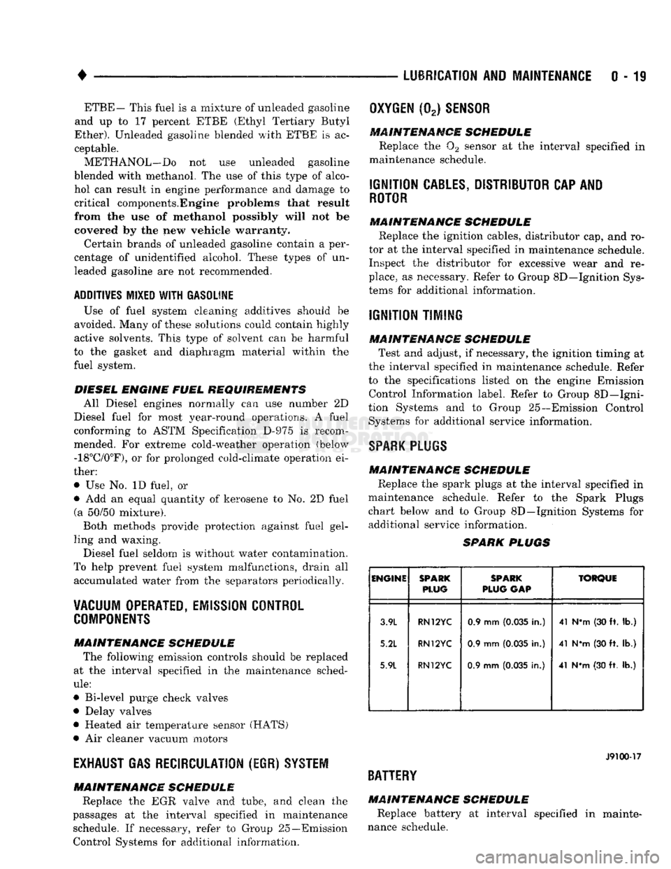
SPARK
PLUGS MAINTENANCE SCHEDULE
Replace the spark plugs at the interval specified in
maintenance schedule. Refer to the Spark Plugs
chart below and to Group 8D—Ignition Systems for additional service information.
SPARK
PLUGS
ENGINE
SPARK
PLUG
SPARK
PLUG
GAP
TORQUE
3.9L
5.2L
5.9L
RN12YC
RN12YC
RN12YC
0.9 mm
(0.035
in.)
0.9 mm
(0.035
in.)
0.9 mm
(0.035
in.) 41 N*m (30 ft. lb.)
41 NVn (30 ft. lb.)
41 N*m (30 ft. lb.)
J9100-17
BATTERY
MAINTENANCE SCHEDULE
Replace battery at interval specified in mainte
nance schedule.
Page 191 of 1502
5
- 4
BRAKES
• (3) During road test, make normal and firm brake
stops in 25-40 mph (40-64 Km/h) range. Note faulty
brake operation such as pull, grab, drag, noise, low
pedal, etc.
(4) Inspect suspect brake components and refer to
problem diagnosis information for causes of various
brake conditions.
COMPONENT
INSPECTION
Fluid leak points and dragging brake units can usu
ally be located without removing any components. The
area around a leak point will be wet with fluid. The
components at a dragging brake unit (wheel, tire, rotor)
will be quite warm or hot to the touch.
Other brake problem conditions will require compo
nent removal for proper inspection. Raise the vehicle and remove the necessary wheels for better visual ac
cess.
DIAGNOSING BRAKE
PROBLEMS
PEDAL FALLS
AWAY
A
brake pedal that falls away under steady foot
pressure is the result of a system leak. The leak
point could be at a brakeline, fitting, hose, or caliper. Internal leakage in the master cylinder caused by
worn or damaged piston cups, may also be the prob lem cause.
If leakage is severe, fluid will be evident at or around
the leaking component. However, internal leakage in
the master cylinder may not be physically evident. Re fer to the cylinder test procedure in this section.
LOW PEDAL
If a low pedal is experienced, pump the pedal sev
eral times. If the pedal comes back up, worn lining
and worn rotors or drums are the likely causes.
A decrease in fluid level in the master cylinder res
ervoirs may only be the result of normal lining wear.
Fluid level can be expected to decrease in proportion to wear. It is a result of the outward movement of
caliper and wheel cylinder pistons to compensate for
normal wear. Top off the reservoir fluid level and
check brake operation to verify proper brake action.
SPONGY PEDAL. A spongy pedal is most often caused by air in the sys
tem. Thin brake drums or substandard brake lines and
hoses can also cause a spongy pedal. The proper course
of action is to bleed the system and replace thin drums and suspect quality brake lines and hoses.
HARD PEDAL
OR
HIGH
PEDAL
EFFORT
A hard pedal or high pedal effort may be due to
lining that is water soaked, contaminated, glazed, or
badly worn. The power booster or check valve could also be faulty. On diesel engine models, high pedal effort may be
the result of a low vacuum condition. If the booster and check valve are OK, the problem may be related
to a vacuum pump hose, hose connection, hose fit
ting, pump diaphragm, or drive gear. Vacuum pump output can be checked with a standard vacuum
gauge. Vacuum output should range from 8.5 to 25 inches vacuum. If vacuum pump output is within
limits,
check the power booster and check valve as
described in this section.
BRAKE DRAG
Brake drag occurs when the lining is in constant
contact with the rotor or drum. Drag can occur at
one wheel, all wheels, fronts only, or rears only. It is a product of incomplete brakeshoe release. Drag can
be minor or severe enough to overheat the linings,
rotors and drums.
Brake drag can also effect fuel economy. If undetec
ted, minor brake drag can be misdiagnosed as an en gine or transmission/torque converter problem.
Minor drag will usually cause slight surface charring
of the lining. It can also generate hard spots in rotors and drums from the overheat-cool down process. In most
cases,
the rotors, drums, wheels and tires are quite
warm to the touch after the vehicle is stopped.
Severe drag can char the brake lining all the way
through. It can also distort and score rotors and drums to the point of replacement. The wheels, tires and brake components will be extremely hot. In se
vere cases, the lining may generate smoke as it chars
from overheating.
Some common causes of brake drag are:
• seized or improperly adjusted parking brake cables
• loose/worn wheel bearing
• seized caliper or wheel cylinder piston
• caliper binding on corroded bushings or rusted
slide surfaces
• loose caliper mounting bracket
• drum brakeshoes binding on worn or damaged sup
port plates
• misassembled components. If brake drag occurs at all wheels, the problem may
be related to a blocked master cylinder return port, or faulty power booster that binds and does not release.
BRAKE FADE
Brake fade is a product of overheating caused by
brake drag. However, brake overheating and subse quent fade can also be caused by riding the brake
pedal, making repeated high deceleration stops in a short time span, or constant braking on steep moun
tain roads. Refer to the Brake Drag information in
this section for additional causes.
PEDAL
PULSA
TION
Pedal pulsation is caused by components that are
loose, out of round, or worn beyond tolerance limits.
Page 291 of 1502
7 - 20
COOLING
SYSTEM
•
HOSE
CLAMP
HOSE
J9207-36
Fig.
16
Hose
Clamp
Tool
WITH AIR
CONDITIONING
(A/C)
REMOVAL
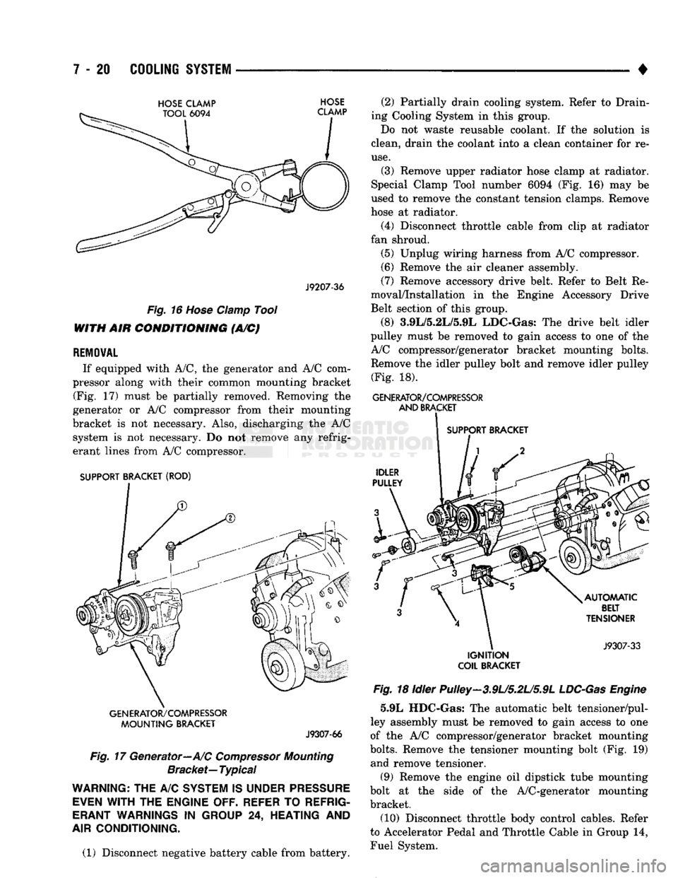
If equipped with A/C, the generator and A/C com
pressor along with their common mounting bracket (Fig. 17) must be partially removed. Removing the
generator or A/C compressor from their mounting
bracket is not necessary. Also, discharging the A/C system is not necessary. Do not remove any refrig
erant lines from A/C compressor.
SUPPORT BRACKET (ROD)
GENERATOR/COMPRESSOR
MOUNTING
BRACKET
J9307-66
Fig.
17 Generator—A/C
Compressor
Mounting
Bracket—
Typical
WARNING;
THE A/C
SYSTEM
IS
UNDER
PRESSURE
EVEN
WITH
THE
ENGINE OFF. REFER
TO
REFRIG
ERANT
WARNINGS
IN
GROUP
24,
HEATING
AND
AIR
CONDITIONING.
(1) Disconnect negative battery cable from battery. (2) Partially drain cooling system. Refer to Drain
ing Cooling System in this group.
Do not waste reusable coolant. If the solution is
clean, drain the coolant into a clean container for re
use.
(3) Remove upper radiator hose clamp at radiator.
Special Clamp Tool number 6094 (Fig. 16) may be
used to remove the constant tension clamps. Remove
hose at radiator.
(4) Disconnect throttle cable from clip at radiator
fan shroud. (5) Unplug wiring harness from A/C compressor.
(6) Remove the air cleaner assembly.
(7) Remove accessory drive belt. Refer to Belt Re
moval/Installation in the Engine Accessory Drive
Belt section of this group.
(8) 3.9L/5.2L/5.9L LDC-Gas: The drive belt idler
pulley must be removed to gain access to one of the
A/C compressor/generator bracket mounting bolts. Remove the idler pulley bolt and remove idler pulley (Fig. 18).
GENERATOR/COMPRESSOR
AND
BRACKET
SUPPORT BRACKET
IGNITION
COIL
BRACKET
Fig.
18 Idler Pulley-3.9U5.2U5.9L
LDC-Gas
Engine
5.9L HDC-Gas: The automatic belt tensioner/pul-
ley assembly must be removed to gain access to one
of the A/C compressor/generator bracket mounting
bolts.
Remove the tensioner mounting bolt (Fig. 19) and remove tensioner.
(9) Remove the engine oil dipstick tube mounting
bolt at the side of the A/C-generator mounting
bracket.
(10) Disconnect throttle body control cables. Refer
to Accelerator Pedal and Throttle Cable in Group 14,
Fuel System.
Page 331 of 1502
8A
- 10
ELECTRICAL
•
STARTING SYSTEM DIAGNOSIS
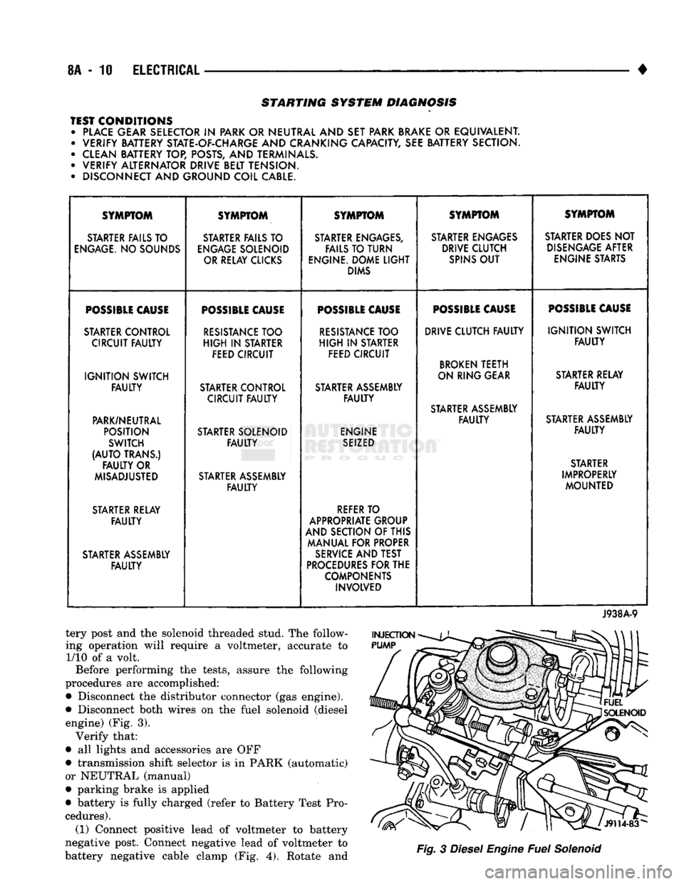
TEST CONDITIONS • PLACE GEAR SELECTOR
IN
PARK OR NEUTRAL AND SET PARK BRAKE
OR
EQUIVALENT. • VERIFY BATTERY STATE-OF-CHARGE AND CRANKING CAPACITY, SEE BATTERY SECTION.
• CLEAN BATTERY TOP, POSTS, AND TERMINALS.
• VERIFY ALTERNATOR DRIVE BELT TENSION.
• DISCONNECT AND GROUND COIL CABLE. SYMPTOM
SYMPTOM SYMPTOM SYMPTOM SYMPTOM
STARTER FAILS TO STARTER FAILS TO STARTER ENGAGES, STARTER ENGAGES STARTER DOES NOT
ENGAGE.
NO SOUNDS
ENGAGE
SOLENOID FAILS TO TURN DRIVE CLUTCH
DISENGAGE
AFTER
OR RELAY CLICKS ENGINE. DOME
LIGHT
SPINS
OUT
ENGINE STARTS
DIMS
POSSIBLE
CAUSE
POSSIBLE
CAUSE
POSSIBLE
CAUSE
POSSIBLE
CAUSE
POSSIBLE
CAUSE
STARTER CONTROL
RESISTANCE
TOO
RESISTANCE
TOO DRIVE CLUTCH
FAULTY
IGNITION
SWITCH
CIRCUIT
FAULTY
HIGH
IN
STARTER
HIGH
IN
STARTER
FAULTY
FEED CIRCUIT FEED CIRCUIT
BROKEN
TEETH
IGNITION
SWITCH ON RING GEAR
STARTER RELAY
FAULTY
STARTER CONTROL STARTER ASSEMBLY
FAULTY
CIRCUIT
FAULTY FAULTY
STARTER ASSEMBLY
PARK/NEUTRAL
FAULTY
STARTER ASSEMBLY
POSITION STARTER SOLENOID ENGINE
FAULTY
SWITCH
FAULTY
SEIZED
(AUTO
TRANS.) STARTER
FAULTY
OR STARTER
MISADJUSTED STARTER ASSEMBLY IMPROPERLY
FAULTY
MOUNTED
STARTER RELAY
REFER
TO
FAULTY
APPROPRIATE GROUP
AND SECTION OF THIS
MANUAL FOR PROPER
STARTER ASSEMBLY
SERVICE
AND TEST
FAULTY
PROCEDURES
FOR THE
COMPONENTS INVOLVED
J938A-9
tery post and the solenoid threaded stud. The follow
ing operation will require a voltmeter, accurate to 1/10 of a volt.
Before performing the tests, assure the following
procedures are accomplished:
•
Disconnect the distributor connector (gas engine).
•
Disconnect both wires on the fuel solenoid (diesel engine) (Fig. 3). Verify that:
•
all lights and accessories are OFF
•
transmission shift selector is in PARK (automatic)
or NEUTRAL (manual)
•
parking brake is applied
•
battery is fully charged (refer to Battery Test Pro
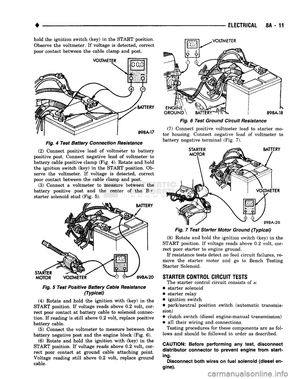
cedures). (1) Connect positive lead of voltmeter to battery
negative post. Connect negative lead of voltmeter to
battery negative cable clamp (Fig. 4). Rotate and
Fig.
3
Diesel
Engine
Fuel
Solenoid
Page 332 of 1502
•
ELECTRICAL
8A - 11 hold the ignition switch (key) in the START position.
Observe the voltmeter. If voltage is detected, correct
poor contact between the cable clamp and post.
VOLTMETER
VOLTMETER
BATTERY
898A-17
Fig.
4 Test
Battery
Connection
Resistance
(2) Connect positive lead of voltmeter to battery
positive post. Connect negative lead of voltmeter to
battery cable positive clamp (Fig. 4). Rotate and hold
the ignition switch (key) in the START position. Ob serve the voltmeter. If voltage is detected, correct
poor contact between the cable clamp and post.
(3) Connect a voltmeter to measure between the
battery positive post and the center of the B + starter solenoid stud (Fig. 5).
BATTERY
STARTER
MOTOR
VOLTMETER
898A-20
Fig.
5 Test Positive
Battery
Cable
Resistance
(Typical)
(4) Rotate and hold the ighition with (key) in the
START position. If voltage reads above 0.2 volt, cor
rect poor contact at battery cable to solenoid connec
tion.
If reading is still above 0.2 volt, replace positive
battery cable.
(5) Connect the voltmeter to measure between the
battery negative post and the engine block (Fig. 6).
(6) Rotate and hold the ignition with (key) in the
START position. If voltage reads above 0.2 volt, cor
rect poor contact at ground cable attaching point.
Voltage reading still above 0.2 volt, replace ground cable.
ENGINE
, ^J^P
GROUND
\
BATTERY
898A-18
Fig.
6 Test
Ground
Circuit
Resistance
(7)
Connect positive voltmeter lead to starter mo
tor housing. Connect negative lead of voltmeter to
battery negative terminal (Fig. 7).
STARTER
MOTOR
BATTERY
VOLTMETER
898A-26
Fig.
7 Test
Starter
Motor
Ground
(Typical)
(8) Rotate and hold the ignition switch (key) in the
START position. If voltage reads above 0.2 volt, cor
rect poor starter to engine ground.
If resistance tests detect no feed circuit failures, re
move the starter motor and go to Bench Testing Starter Solenoid.
STARTER
CONTROL
CIRCUIT
TESTS
The starter control circuit consists of a:
• starter solenoid
• starter relay
• ignition switch
• park/neutral position switch (automatic transmis sion)
• clutch switch (diesel engine-manual transmission)
• all their wiring and connections.
Testing procedures for these components are as fol
lows and should be followed in order as described.
CAUTION:
Before
performing
any
test,
disconnect
distributor
connector
to
prevent
engine
from
start
ing.
Disconnect
both
wires
on
fuel
solenoid
(diesel
en
gine).
Page 338 of 1502
•
ELECTRICAL
8A - 17
DIAGNOSTIC
TROUBLE
CODES
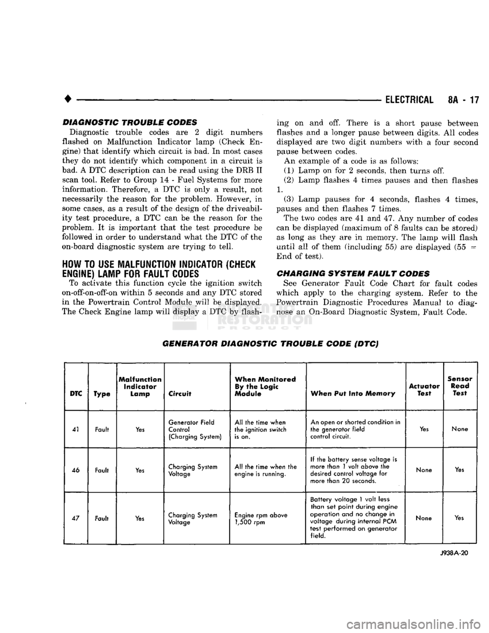
Diagnostic trouble codes are 2 digit numbers
flashed on Malfunction Indicator lamp (Check En
gine) that identify which circuit is bad. In most cases
they do not identify which component in a circuit is
bad. A DTC description can be read using the DRB II scan tool. Refer to Group 14 - Fuel Systems for more
information. Therefore, a DTC is only a result, not
necessarily the reason for the problem. However, in
some cases, as a result of the design of the driveabil- ity test procedure, a DTC can be the reason for the
problem. It is important that the test procedure be followed in order to understand what the DTC of the
on-board diagnostic system are trying to tell.
HOW
TO
USE
MALFUNCTION
INDICATOR
(CHECK
ENGINE)
LAMP
FOR
FAULT
CODES
To activate this function cycle the ignition switch
on-off-on-off-on within 5 seconds and any DTC stored
in the Powertrain Control Module will be displayed.
The Check Engine lamp will display a DTC by flash ing on and off. There is a short pause between
flashes and a longer pause between digits. All codes
displayed are two digit numbers with a four second
pause between codes. An example of a code is as follows:
(1) Lamp on for 2 seconds, then turns off.
(2) Lamp flashes 4 times pauses and then flashes
1.
(3) Lamp pauses for 4 seconds, flashes 4 times,
pauses and then flashes 7 times.
The two codes are 41 and 47. Any number of codes
can be displayed (maximum of 8 faults can be stored) as long as they are in memory. The lamp will flash
until all of them (including 55) are displayed (55 =
End of test).
CHARGING
SYSTEM
FAULT
CODES
See Generator Fault Code Chart for fault codes
which apply to the charging system. Refer to the
Powertrain Diagnostic Procedures Manual to diag
nose an On-Board Diagnostic System, Fault Code.
GENERATOR
DIAGNOSTIC
TROUBLE
CODE
(DTC)
DTC
Type
Malfunction
Indicator
Lamp
Circuit
When
Monitored
By
the
Logic
Module
When
Put Into
Memory
Actuator
Test
Sensor
Read
Test
41 Fault
Yes
Generator Field
Control
(Charging
System)
All the
time
when
the ignition switch
is
on.
An
open or shorted condition in
the generator
field
control circuit.
Yes
None
46 Fault
Yes
Charging
System
Voltage
All the
time
when the
engine
is
running.
If the
battery
sense
voltage is
more than 1 volt
above
the
desired
control voltage for
more than 20
seconds.
None
Yes
47 Fault
Yes
Charging
System
Voltage
Engine
rpm
above
1,500 rpm Battery voltage
1
volt
less
than set point during engine
operation and no
change
in
voltage
during
internal
PCM
test performed on generator field.
None
Yes
J938A-20
Page 352 of 1502
•
IGNITION
SYSTEMS
8D
- 1
CONTENTS
page page
COMPONENT IDENTIFICATION/SYSTEM DIAGNOSTICS/SERVICE PROCEDURES
7
OPERATION
1
IGNITION SWITCH
25
COMPONENT REMOVAL/INSTALLATION
..... 18
SPECIFICATIONS
28
COMPONENT
IDENTIFICATION/SYSTEM OPERATION
INDEX
page
Automatic
Shut Down (ASD) Relay
1
Camshaft Position Sensor
2
Crankshaft Position Sensor
2
Distributors
3
Engine Coolant
Temperature
Sensor
...........
4
General
Information
1
page
Ignition
Coil
3
Intake
Manifold Charge
Air
Temperature
Sensor
. . 4
Manifold Absolute Pressure (MAP) Sensor
4
Powertrain
Control
Module (PCM)
. 5
Throttle
Position Sensor
5
GENERAL
INFORMATION
Throughout this group, references
are
made
to
par
ticular vehicle models
by
alphabetical designation
or
by
the
particular vehicle nameplate.
A
chart showing a breakdown
of
alphabetical designations
is
included
in
the
Introduction group
at the
beginning
of
this
manual. 5.9L
gas
powered engines will
be
referred
to as ei
ther: LDC (Light Duty Cycle),
or
HDC (Heavy Duty Cycle). This section
of the
group, Component Identifica
tion/System Operation, will discuss ignition system operation
and
will identify ignition system compo
nents.
For diagnostic procedures
and
adjustments, refer
to
the Diagnostics/Service Procedures section
of
this
group.
For removal
and
installation
of
ignition system
components, refer
to the
Component Removal/Instal
lation section
of
this group. For other useful information, refer
to
On-Board
Di
agnostics
in the
General Diagnosis sections
of
Group
14,
Fuel System
in
this manual. For operation
of the DRB II
Diagnostic Scan Tool,
refer
to the
appropriate Powertrain Diagnostic Proce
dures service manual.
An Ignition specifications section
is
included
at the
end
of
this group.
A
general Maintenance Schedule (mileage intervals)
for
ignition related items
can be
found
in
Group
0,
Lubrication and Maintenance. This
schedule
can
also
be
found
in the
Owners Manual.
IGNITION
SYSTEMS
The ignition systems used
on all
engines
are
basi
cally identical. Similarities
and
differences between
the systems will
be
discussed.
A sequential multi-port fuel injection system
is
used
on all gas
powered engines.
The ignition system
is
controlled
by the
powertrain
control module (PCM)
on all
engines.
The
PCM
was
formerly referred
to as the
SBEC
or
engine control ler.
The ignition system consists
of:
• Spark Plugs
• Ignition Coil
• Secondary Ignition Cables
• Ignition distributor. Contains rotor
and
camshaft
position sensor • Powertrain Control Module (PCM)
• Crankshaft Position Sensor
AUTOMATIC SHUT DOWN (ASD) RELAY
The automatic shut down (ASD) relay
is
located
in
the engine compartment (Fig.
1). As one of its
func
tions,
the ASD
relay will supply battery voltage
to
the ignition coil.
The
ground circuit
for the
ASD
re
lay
is
controlled
by the
powertrain control module (PCM).
The PCM
regulates
ASD
relay operation
by
switching
the
ground circuit on-and-off.
IGNITION
SYSTEMS
Page 353 of 1502
8D
- 2
IGNITION
SYSTEMS
•
A/C
CLUTCH RELAY STARTER RELAY
DATA LINK CONTROL
CONNECTOR
MODULE J9314-164
Fig.
1
Auto
Shut Down
Relay
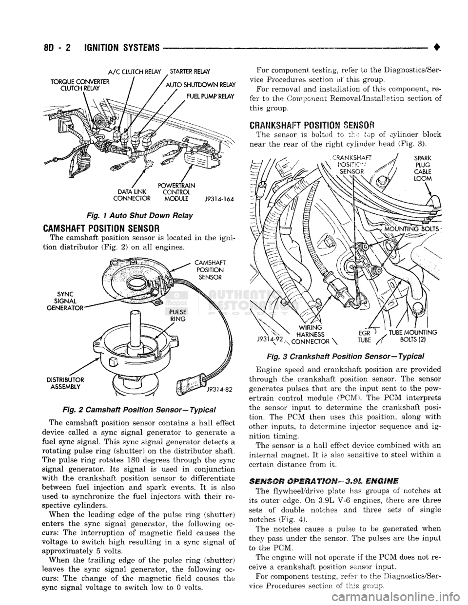
CAMSHAFT POSITION SENSOR
The camshaft position sensor is located in the igni
tion distributor (Fig. 2) on all engines.
Fig.
2 Camshaft Position
Sensor—
Typical
The camshaft position sensor contains a hall effect
device called a sync signal generator to generate a
fuel sync signal. This sync signal generator detects a
rotating pulse ring (shutter) on the distributor shaft.
The pulse ring rotates 180 degrees through the sync signal generator. Its signal is used in conjunction
with the crankshaft position sensor to differentiate
between fuel injection and spark events. It is also
used to synchronize the fuel injectors with their re spective cylinders.
When the leading edge of the pulse ring (shutter)
enters the sync signal generator, the following oc
curs:
The interruption of magnetic field causes the
voltage to switch high resulting in a sync signal of approximately 5 volts.
When the trailing edge of the pulse ring (shutter)
leaves the sync signal generator, the following oc
curs:
The change of the magnetic field causes the sync signal voltage to switch low to 0 volts. For component testing, refer to the Diagnostics/Ser
vice Procedures section of this group. For removal and installation of this component, re
fer to the Component Removal/Installation section of this group.
CRANKSHAFT
POSITION
SENSOR
The sensor is bolted to the top of cylinder block
near the rear of the right cylinder head (Fig. 3).
Fig.
3 Crankshaft Position Sensor—Typical
*
Engine speed and crankshaft position are provided
through the crankshaft position sensor. The sensor generates pulses that are the input sent to the pow
ertrain control module (PCM). The PCM interprets
the sensor input to determine the crankshaft posi
tion. The PCM then uses this position, along with other inputs, to determine injector sequence and ig
nition timing.
The sensor is a hall effect device combined with an
internal magnet. It is also sensitive to steel within a
certain distance from it.
SENSOR
OPERATION-3.9L
ENGINE
The flywheel/drive plate has groups of notches at
its outer edge. On 3.9L V-6 engines, there are three sets of double notches and three sets of single
notches (Fig.
4).
The notches cause a pulse to be generated when
they pass under the sensor. The pulses are the input to the PCM.
The engine will not operate if the PCM does not re
ceive a crankshaft position sensor input.
For component testing, refer to the Diagnostics/Ser
vice Procedures section of this group.