fuel DODGE TRUCK 1993 Service Owner's Manual
[x] Cancel search | Manufacturer: DODGE, Model Year: 1993, Model line: TRUCK, Model: DODGE TRUCK 1993Pages: 1502, PDF Size: 80.97 MB
Page 354 of 1502
•
IGNITION
SYSTEMS
8D - 3 For removal and installation of this sensor, refer to
the Component Removal/Installation section of this
group.
CRANKSHAFT
POSITION
SENSOR
NOTCHES- FLYWHEEL CRANKSHAFT
POSITION-
SENSOR
NOTCHES* .FLYWHEEL
J9314-88
—^^j^jV^
J9314-89
Fig.
4
Sensor
Operation—3.9L
Engine
SENSOR
OPERATION'-5.2U5.9L
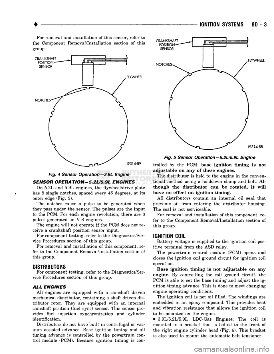
ENGINES On 5.2L and 5.9L engines, the flywheel/drive plate
has 8 single notches, spaced every 45 degrees, at its outer edge (Fig. 5).
The notches cause a pulse to be generated when
they pass under the sensor. The pulses are the input to the PCM. For each engine revolution, there are 8
pulses generated on V-8 engines.
The engine will not operate if the PCM does not re
ceive a crankshaft position sensor input. For component testing, refer to the Diagnostics/Ser
vice Procedures section of this group.
For removal and installation of this component, re
fer to the Component Removal/Installation section of
this group.
DISTRIBUTORS
For component testing, refer to the Diagnostics/Ser
vice Procedures section of this group.
ALL
ENGINES All engines are equipped with a camshaft driven
mechanical distributor, containing a shaft driven dis
tributor rotor. They are equipped with an internal camshaft position (fuel sync) sensor. This sensor pro
vides fuel injection synchronization and cylinder identification.
Distributors do not have built in centrifugal or vac
uum assisted advance. Base ignition timing and all
timing advance is controlled by the powertrain con
trol module (PCM). Because ignition timing is con-
Fig.
5
Sensor
Opera tion—5.2L/5.9L
Engine
trolled by the PCM, base ignition timing is not adjustable on any of these engines.
The distributor is held to the engine in the conven
tional method using a holddown clamp and bolt. Al
though the distributor can be rotated, it will
have no effect on ignition timing.
All distributors contain an internal oil seal that
prevents oil from entering the distributor housing.
The seal is not serviceable.
For removal and installation of this component, re
fer to the Component Removal/Installation section of
this group.
IGNITION
COIL
Battery voltage is supplied to the ignition coil pos
itive terminal from the ASD relay. The powertrain control module (PCM) opens and
closes the ignition coil ground circuit for ignition coil operation. Base ignition timing is not adjustable on any
engine. By controlling the coil ground circuit, the
PCM is able to set the base timing and adjust the ig nition timing advance. This is done to meet changing engine operating conditions. The ignition coil is not oil filled. The windings are
embedded in an epoxy compound. This provides heat and vibration resistance that allows the ignition coil
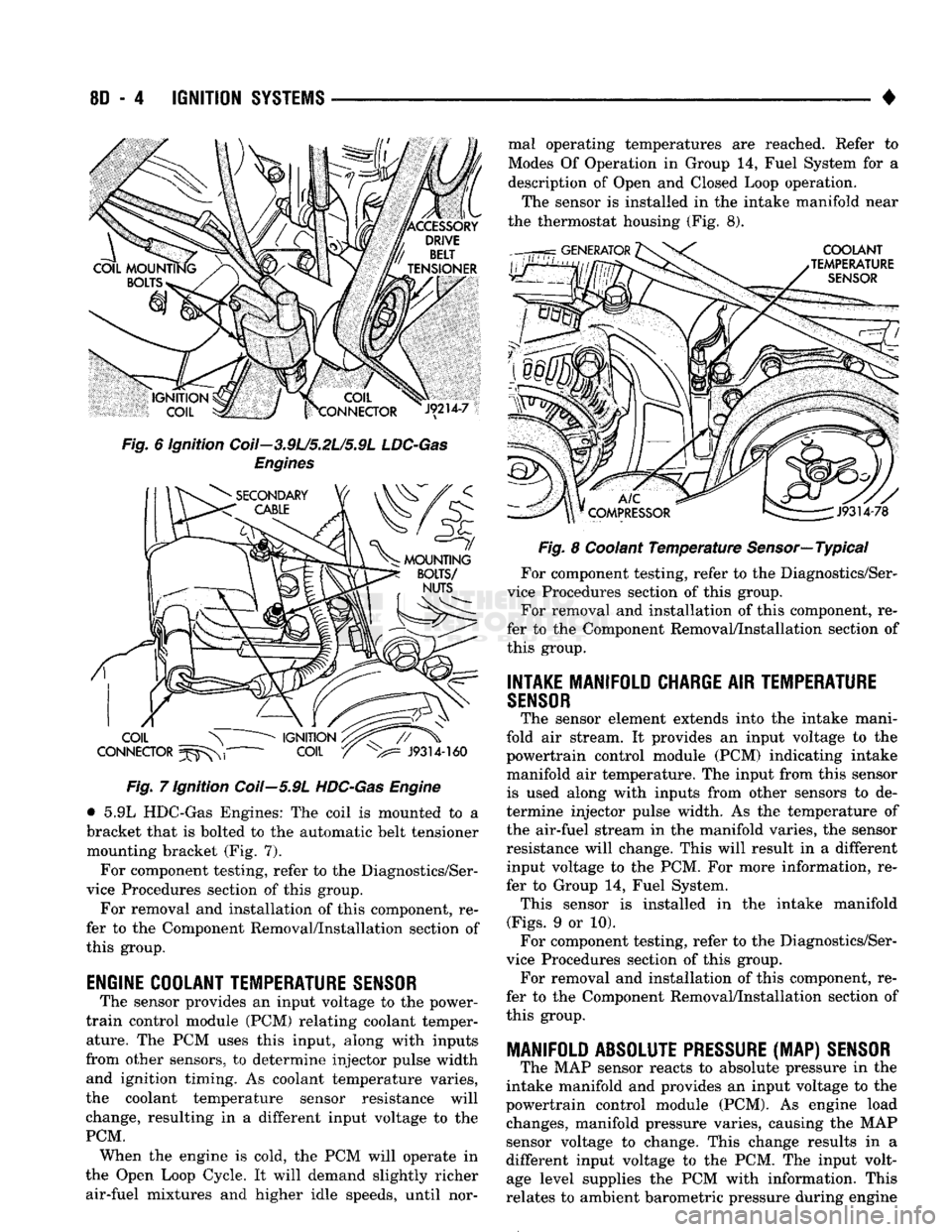
to be mounted on the engine. • 3.9L/5.2L/5.9L LDC-Gas Engines: The coil is
mounted to a bracket that is bolted to the front of the right engine cylinder head (Fig. 6). This bracket is also used to mount the automatic belt tensioner.
Page 355 of 1502
8D
- 4
IGNITION
SYSTEMS
•
Fig. 6 ignition Coil—3.9L/5.2L/5.9L
LDC-Gas
Engines Fig. 7 Ignition Coil—5.9L
HDC-Gas
Engine
• 5.9L HDC-Gas Engines: The coil is mounted to a
bracket that is bolted to the automatic belt tensioner mounting bracket (Fig. 7).
For component testing, refer to the Diagnostics/Ser
vice Procedures section of this group.
For removal and installation of this component, re
fer to the Component Removal/Installation section of
this group.
ENGINE COOLANT TEMPERATURE
SENSOR
The sensor provides an input voltage to the power-
train control module (PCM) relating coolant temper ature. The PCM uses this input, along with inputs
from other sensors, to determine injector pulse width and ignition timing. As coolant temperature varies,
the coolant temperature sensor resistance will
change, resulting in a different input voltage to the
PCM. When the engine is cold, the PCM will operate in
the Open Loop Cycle. It will demand slightly richer air-fuel mixtures and higher idle speeds, until nor mal operating temperatures are reached. Refer to
Modes Of Operation in Group 14, Fuel System for a
description of Open and Closed Loop operation.
The sensor is installed in the intake manifold near
the thermostat housing (Fig. 8).
Fig. 8 Coolant Temperature Sensor—Typical
For component testing, refer to the Diagnostics/Ser
vice Procedures section of this group. For removal and installation of this component, re
fer to the Component Removal/Installation section of
this group.
INTAKE MANIFOLD CHARGE
AIR
TEMPERATURE
SENSOR
The sensor element extends into the intake mani
fold air stream. It provides an input voltage to the
powertrain control module (PCM) indicating intake
manifold air temperature. The input from this sensor is used along with inputs from other sensors to de
termine injector pulse width. As the temperature of
the air-fuel stream in the manifold varies, the sensor
resistance will change. This will result in a different input voltage to the PCM. For more information, re
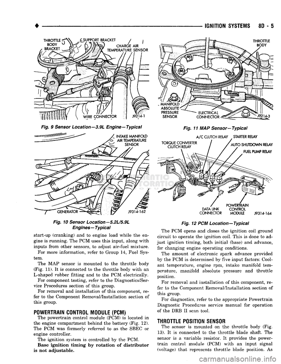
fer to Group 14, Fuel System. This sensor is installed in the intake manifold
(Figs.
9 or 10). For component testing, refer to the Diagnostics/Ser
vice Procedures section of this group. For removal and installation of this component, re
fer to the Component Removal/Installation section of
this group.
MANIFOLD ABSOLUTE
PRESSURE
(MAP)
SENSOR
The MAP sensor reacts to absolute pressure in the
intake manifold and provides an input voltage to the
powertrain control module (PCM). As engine load changes, manifold pressure varies, causing the MAP
sensor voltage to change. This change results in a
different input voltage to the PCM. The input volt age level supplies the PCM with information. This
relates to ambient barometric pressure during engine
Page 356 of 1502
•
IGNITION
SYSTEMS
8D - 5
THROTTLE
^
BODY
u
BRACKET
y^SUPPORT
BRACKET
/ |
CHARGE
AIR
ijmmmmk
TEMPERATURE
SENSOR
THROTTLE
BODY
Fig.
9
Sensor
Location—3.9L Engine—Typical
INTAKE MANIFOLD
'b AIR TEMPERATURE
SENSOR
J9314-162
Fig.
10
Sensor
Location—5.2L/5.9L
Engines—Typical
start-up (cranking) and to engine load while the en
gine is running. The PCM uses this input, along with
inputs from other sensors, to adjust air-fuel mixture.
For more information, refer to Group 14, Fuel Sys
tem.
The MAP sensor is mounted to the throttle body
(Fig. 11). It is connected to the throttle body with an
L-shaped rubber fitting and to the PCM electrically. For component testing, refer to the Diagnostics/Ser
vice Procedures section of this group. For removal and installation of this component, re
fer to the Component Removal/Installation section of
this group.
POWERTRAIN CONTROL MODULE
(PCM) The powertrain control module (PCM) is located in
the engine compartment behind the battery (Fig. 12).
The PCM was formerly referred to as the SBEC or engine controller. The ignition system is controlled by the PCM. Base ignition timing by rotation of distributor
is not adjustable.
MANIFOLD
ABSOLUTE
PRESSURE
SENSOR
TORQUE CONVERTER CLUTCH RELAY
ELECTRICAL
Jlp^
CONNECTOR
^gis!—
Fig.
11 MAP Sensor—Typical
A/C
CLUTCH RELAY STARTER RELAY
AUTO
SHUTDOWN RELAY FUEL PUMP RELAY
DATA LINK
CONNECTOR POWERTRAIN
CONTROL
MODULE
J9314-164
Fig.
12 PCM Location—Typical The PCM opens and closes the ignition coil ground
circuit to operate the ignition coil. This is done to ad
just ignition timing, both initial (base) and advance, for changing engine operating conditions.
The amount of electronic spark advance provided
by the PCM is determined by five input factors: Cool ant temperature, engine rpm, intake manifold tem
perature, manifold absolute pressure and throttle
position.
For removal and installation of this component, re
fer to the Component Removal/Installation section of
this group.
For diagnostics, refer to the appropriate Powertrain
Diagnostic Procedures service manual for operation
of the DRB II scan tool.
THROTTLE
POSITION
SENSOR
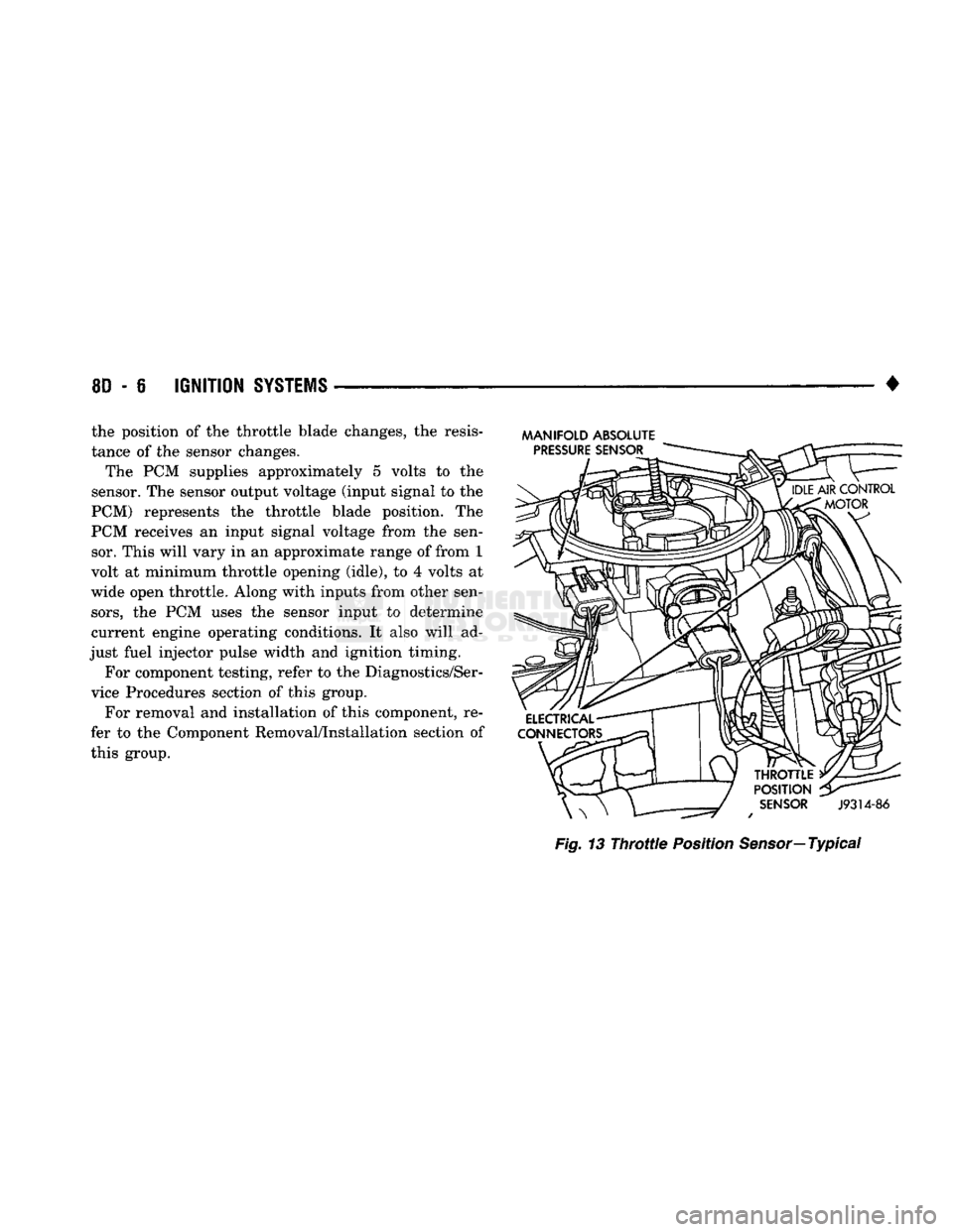
The sensor is mounted on the throttle body (Fig.
13).
It is connected to the throttle blade shaft. The
sensor is a variable resistor. It provides the power-
train control module (PCM) with an input signal (voltage) that represents throttle blade position. As
Page 357 of 1502
8D
- 6
IGNITION
SYSTEMS
• the position of the throttle blade changes, the resis
tance of the sensor changes.
The PCM supplies approximately 5 volts to the
sensor. The sensor output voltage (input signal to the
PCM) represents the throttle blade position. The
PCM receives an input signal voltage from the sen sor. This will vary in an approximate range of from 1
volt at minimum throttle opening (idle), to 4 volts at
wide open throttle. Along with inputs from other sen
sors,
the PCM uses the sensor input to determine
current engine operating conditions. It also will ad
just fuel injector pulse width and ignition timing.
For component testing, refer to the Diagnostics/Ser
vice Procedures section of this group.
For removal and installation of this component, re
fer to the Component Removal/Installation section of
this group.
MANIFOLD ABSOLUTE
Fig.
13
Throttle
Position
Sensor—
Typical
Page 358 of 1502
•
IGNITION
SYSTEMS
80 - 7
DIAGNOSTICS/SERW1CE
PROCEDURES
INDEX
page
Automatic Shut Down (ASD) Relay
7
Camshaft Position
Sensor
Test
...............
7
Crankshaft Position
Sensor
Test
8
Distributor
Cap
8
Distributor
Rotor
8
Engine
Coolant Temperature
Sensor
Test
10
General
Information
7
Ignition
Coil
8
Ignition
Secondary
Circuit
Diagnosis
10
GENERAL
INFORMATION
This section
of the
group, Diagnostics/Service Pro
cedures, will discuss basic ignition system diagnos
tics
and
service adjustments. For system operation
and
component identification,
refer
to the
Component Identification/System Opera
tion section
of
this group. For removal
or
installation
of
ignition system com
ponents, refer
to the
Component Removal/Installa
tion section
of
this group. For other useful information, refer
to
On-Board
Di
agnostics
in the
General Diagnosis sections
of
Group
14,
Fuel System
in
this manual. For operation
of the DRB II
Diagnostic Scan Tool,
refer
to the
appropriate Powertrain Diagnostic Proce
dures service manual.
AUTOMATIC SHUT DOWN
(ASD)
RELAY
Refer
to
Relays—Operation/Testing
in the
Group
14,
Fuel System section
of
this service manual.
CAMSHAFT POSITION SENSOR TEST
The camshaft position sensor
is
located
in the
dis
tributor
on all
engines. To perform
a
complete test
of
this sensor
and its
circuitry, refer
to the DRB II
diagnostic scan tool.
Also refer
to the
appropriate Powertrain Diagnostics
Procedures manual.
To
test
the
sensor only, refer
to
the following: For this test,
an
analog (non-digital) voltmeter
is needed.
Do not
remove
the
distributor connector from
the
distributor. Using small paper clips, insert
them into
the
backside
of the
distributor wire har ness connector
to
make contact with
the
terminals.
Be sure that
the
connector
is not
damaged when
in
serting
the
paper clips. Attach voltmeter leads
to
these paper clips. (1) Connect
the
positive (
+
)
voltmeter lead into
the sensor output wire. This
is at
done
the
distribu tor wire harness connector.
For
wire identification,
refer
to
Group
8W,
Wiring Diagrams.
page
Ignition
Timing
12
Intake Manifold Charge
Air
Temperature
Sensor
Test
12
Manifold Absolute Pressure (MAP)
Sensor
Test
. 12
Oxygen
Sensor
Tests
17
Powertrain Control Module (PCM)
............
14
Spark
Plug Secondary Cables
16
Spark
Plugs
............................
14
Throttle
Position
Sensor
Test
17
(2) Connect
the
negative
(-)
voltmeter lead into
the
ground wire.
For
wire identification, refer
to
Group
8W, Wiring Diagrams.
(3)
Set the
voltmeter
to the 15
Volt
DC
scale. (4) Remove distributor
cap
from distributor
(two
screws). Rotate (crank)
the
engine until
the
distribu
tor rotor
is
pointed towards
the
rear
of
vehicle.
The
movable pulse ring should
now be
within
the
sensor
pickup.
(5) Turn ignition
key to ON
position. Voltmeter
should read approximately
5.0
volts.
(6)
If
voltage
is not
present, check
the
voltmeter
leads
for a
good connection.
(7)
If
voltage
is
still
not
present, check
for
voltage
at
the
supply wire.
For
wire identification, refer
to
Group
8W,
Wiring Diagrams.
(8)
If
voltage
is not
present
at
supply wire, check
for voltage
at
pin-7
of
powertrain control module (PCM) 60-way connector. Leave
the PCM
connector
connected
for
this test. (9)
If
voltage
is
still
not
present, perform vehicle
test using
the DRB II
diagnostic scan tool. (10)
If
voltage
is
present
at
pin-7,
but not at the
supply wire: (a) Check continuity between
the
supply wire.
This
is
checked between
the
distributor connector and pin-7
at the PCM. If
continuity
is not
present,
repair
the
harness
as
necessary. (b) Check
for
continuity between
the
camshaft
position sensor output wire
and
pin-44
at the PCM.
If continuity
is not
present, repair
the
harness
as
necessary. (c) Check
for
continuity between
the
ground cir
cuit wire
at the
distributor connector
and
ground.
If continuity
is not
present, repair
the
harness
as
necessary. (11) While observing
the
voltmeter, crank
the en
gine with ignition switch.
The
voltmeter needle should fluctuate between
0 and 5
volts while
the en
gine
is
cranking. This verifies that
the
camshaft
po
sition sensor
in the
distributor
is
operating properly
and
a
sync pulse signal
is
being generated.
Page 362 of 1502
*
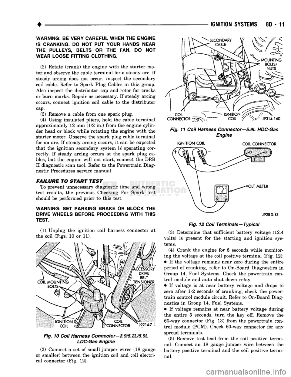
(1) Unplug the ignition coil harness connector at
the coil (Figs. 10 or 11).
Fig.
10
Coil
Harness
Connector—3.9/5.2L/5.9L
LDC-Gas
Engine
(2) Connect a set of small jumper wires (18 gauge
or smaller) between the ignition coil and coil electri
cal connector (Fig. 12).
IGNITION
SYSTEMS
80 - 11
Fig.
11
Coil
Harness
Connector—5.9L
HDC-Gas
Engine
IGNITION
COIL COIL CONNECTOR
J928D-13
Fig.
12
Coil
Terminals—Typical (3) Determine that sufficient battery voltage (12.4
volts) is present for the starting and ignition sys
tems.
(4) Crank the engine for 5 seconds while monitor
ing the voltage at the coil positive terminal (Fig. 12):
• If the voltage remains near zero during the entire
period of cranking, refer to On-Board Diagnostics in Group 14, Fuel Systems. Check the powertrain con
trol module and auto shut down relay.
• If voltage is at near battery voltage and drops to
zero after 1-2 seconds of cranking, check the power-
train control module circuit. Refer to On-Board Diag nostics in Group 14, Fuel Systems.
• If voltage remains at near battery voltage during
the entire 5 seconds, turn the key off. Remove the 60-way connector (Fig. 13) from the powertrain con
trol module (PCM). Check 60-way connector for any spread terminals.
(5) Remove test lead from the coil positive termi
nal.
Connect an 18 gauge jumper wire between the
battery positive terminal and the coil positive termi
nal.
WARNING: BE VERY CAREFUL WHEN THE ENGINE
IS
CRANKING.
DO NOT PUT
YOUR HANDS NEAR
THE PULLEYS, BELTS
OR THE FAN. DO NOT
WEAR LOOSE
FITTING
CLOTHING.
(2) Rotate (crank) the engine with the starter mo
tor and observe the cable terminal for a steady arc. If steady arcing does not occur, inspect the secondary
coil cable. Refer to Spark Plug Cables in this group.
Also inspect the distributor cap and rotor for cracks
or burn marks. Repair as necessary. If steady arcing occurs, connect ignition coil cable to the distributor
cap.
(3) Remove a cable from one spark plug.
(4) Using insulated pliers, hold the cable terminal
approximately 12 mm (1/2 in.) from the engine cylin
der head or block while rotating the engine with the starter motor. Observe the spark plug cable terminal
for an arc. If steady arcing occurs, it can be expected
that the ignition secondary system is" operating cor rectly. If steady arcing occurs at the spark plug ca
bles,
but the engine will not start, connect the DRB II diagnostic scan tool. Refer to the Powertrain Diag
nostic Procedures service manual.
FAILURE
TO START TEST To prevent unnecessary diagnostic time and wrong
test results, the previous Checking For Spark test should be performed prior to this test.
WARNING: SET PARKING BRAKE
OR
BLOCK
THE
DRIVE WHEELS BEFORE PROCEEDING
WITH
THIS
TEST.
Page 363 of 1502
8D
- 12
IGNITION
SYSTEMS
•
XX
oooooooooo
,0000000000
\2141
3%
lOOOOOOOOOO
OOOOOOOOOO
si
20
fcji^OQOOOOOOJ
«r
~
• • -
•
- - #
•oooooooooo.
CONNECTOR
TERMINAL
SIDE
SHOWN
J908D-42
Fig. 13 PCM 60-Way Connector
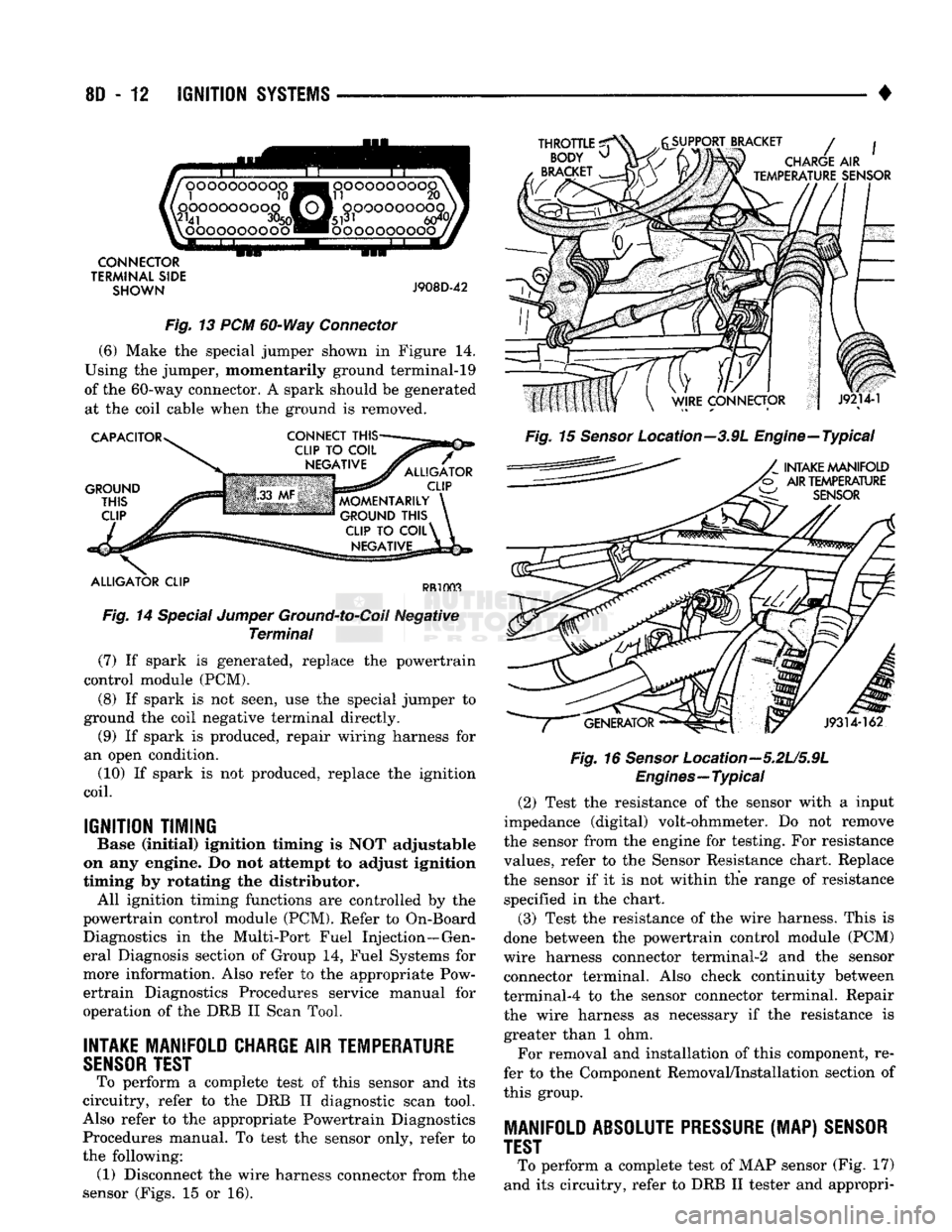
(6) Make the special jumper shown in Figure 14.
Using the jumper, momentarily ground terminal-19
of the 60-way connector. A spark should be generated at the coil cable when the ground is removed.
CAPACITOR
GROUND
THIS
CLIP
CONNECT
THIS-
ALLIGATOR
CLIP
MOMENTARILY
GROUND
THIS
CLIP
TO
COIL^
NEGATIVE
ALLIGATOR
CLIP
PR1003
Fig. 14 Special Jumper Ground-to-Coil Negative Terminal (7) If spark is generated, replace the powertrain
control module (PCM).
(8) If spark is not seen, use the special jumper to
ground the coil negative terminal directly. (9) If spark is produced, repair wiring harness for
an open condition. (10) If spark is not produced, replace the ignition
coil.
IGNITION TIMING
Base (Initial) ignition timing Is NOT adjustable
on any engine. Do not attempt to adjust Ignition
timing by rotating the distributor. All ignition timing functions are controlled by the
powertrain control module (PCM). Refer to On-Board Diagnostics in the Multi-Port Fuel Injection—Gen
eral Diagnosis section of Group 14, Fuel Systems for
more information. Also refer to the appropriate Pow ertrain Diagnostics Procedures service manual for
operation of the DRB II Scan Tool.
INTAKE
MANIFOLD
CHARGE
AIR
TEMPERATURE
SENSOR
TEST
To perform a complete test of this sensor and its
circuitry, refer to the DRB II diagnostic scan tool.
Also refer to the appropriate Powertrain Diagnostics Procedures manual. To test the sensor only, refer to
the following: (1) Disconnect the wire harness connector from the
sensor (Figs. 15 or 16).
THROTTLE
^
BODY
^
BRACKET
SUPPORT BRACKET
/
CHARGE
AIR
TEMPERATURE
SENSOR
Fig. 15 Sensor Location--3.9L Engine—Typical
INTAKE
MANIFOLD
AIR
TEMPERATURE
W
SENSOR
J9314-162
Fig. 16
Sensor
Location—5.2U5.9L
Engines—Typical
(2) Test the resistance of the sensor with a input
impedance (digital) volt-ohmmeter. Do not remove
the sensor from the engine for testing. For resistance
values, refer to the Sensor Resistance chart. Replace
the sensor if it is not within the range of resistance specified in the chart.
(3) Test the resistance of the wire harness. This is
done between the powertrain control module (PCM)
wire harness connector terminal-2 and the sensor connector terminal. Also check continuity between
terminal-4 to the sensor connector terminal. Repair
the wire harness as necessary if the resistance is greater than 1 ohm.
For removal and installation of this component, re
fer to the Component Removal/Installation section of
this group.
MANIFOLD
ABSOLUTE PRESSURE
(MAP)
SENSOR
TEST
To perform a complete test of MAP sensor (Fig. 17)
and its circuitry, refer to DRB II tester and appropri-
Page 365 of 1502
8D
- 14
IGNITION SYSTEMS
• (5) Test the MAP sensor ground circuit at sensor
connector terminal-A (Fig. 19) and PCM connector
terminal-4. Repair the wire harness if necessary.
(6) Test the MAP sensor ground circuit at the
PCM connector between terminal-4 and terminal-11
with an ohmmeter. If the ohmmeter indicates an
open circuit, inspect for a defective sensor ground
connection. Refer to Group 8W, Wiring for location of
this connection. If the ground connection is good, re
place the PCM. If terminal-4 has a short circuit to 12 volts +, correct this condition before replacing the
PCM.
POWERTRAIN
CONTROL MODULE {PCM)
The PCM (formerly called the SBEC or engine -con
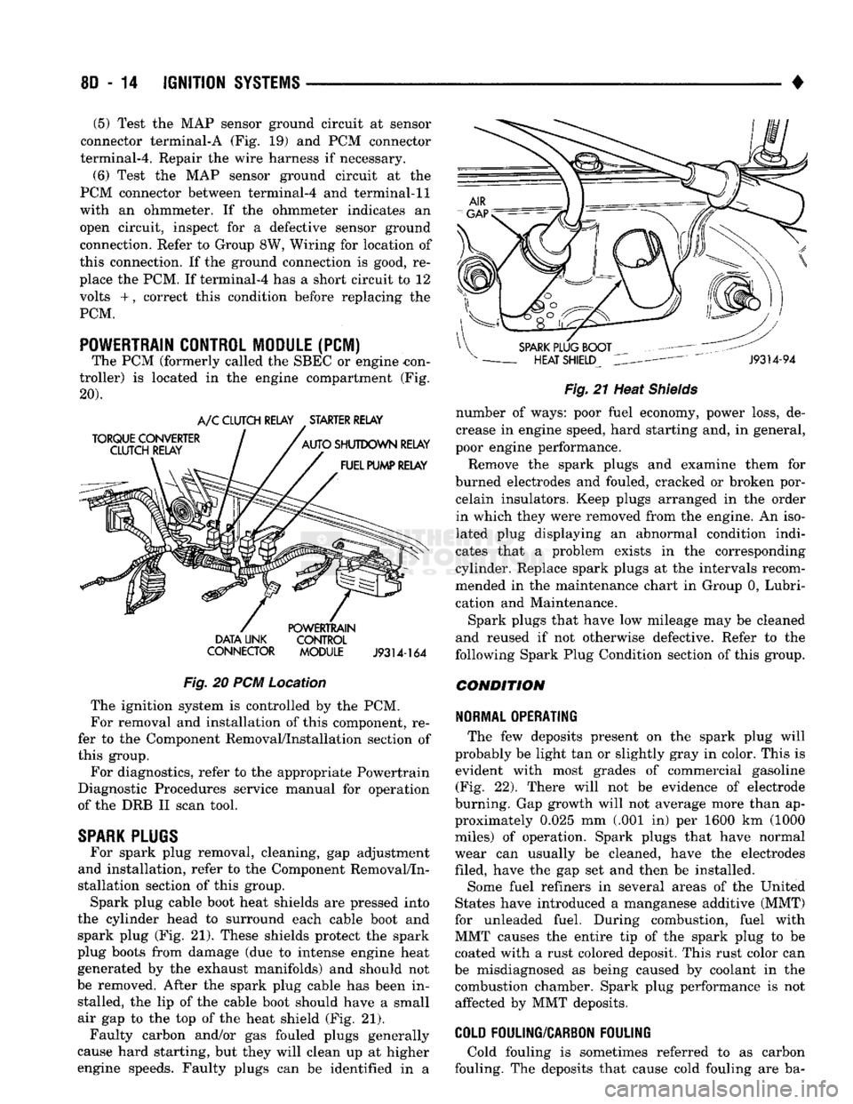
troller) is located in the engine compartment (Fig.
20). DATA UNK CONTROL
CONNECTOR MODULE
J9314-164
Fig.
20 PCM Location The ignition system is controlled by the PCM.
For removal and installation of this component, re
fer to the Component Removal/Installation section of
this group.
For diagnostics, refer to the appropriate Powertrain
Diagnostic Procedures service manual for operation
of the DRB II scan tool.
SPARK
PLUGS
For spark plug removal, cleaning, gap adjustment
and installation, refer to the Component Removal/In
stallation section of this group. Spark plug cable boot heat shields are pressed into
the cylinder head to surround each cable boot and
spark plug (Fig. 21). These shields protect the spark
plug boots from damage (due to intense engine heat
generated by the exhaust manifolds) and should not
be removed. After the spark plug cable has been in stalled, the lip of the cable boot should have a small
air gap to the top of the heat shield (Fig. 21). Faulty carbon and/or gas fouled plugs generally
cause hard starting, but they will clean up at higher
engine speeds. Faulty plugs can be identified in a
Fig.
21 Heat
Shields
number of ways: poor fuel economy, power loss, de
crease in engine speed, hard starting and, in general,
poor engine performance.
Remove the spark plugs and examine them for
burned electrodes and fouled, cracked or broken por celain insulators. Keep plugs arranged in the order
in which they were removed from the engine. An iso
lated plug displaying an abnormal condition indi
cates that a problem exists in the corresponding
cylinder. Replace spark plugs at the intervals recom
mended in the maintenance chart in Group 0, Lubri
cation and Maintenance.
Spark plugs that have low mileage may be cleaned
and reused if not otherwise defective. Refer to the
following Spark Plug Condition section of this group.
CONDITION
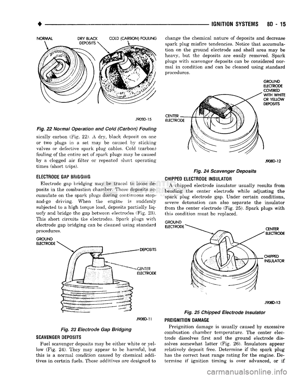
NORMAL OPERATING
The few deposits present on the spark plug will
probably be light tan or slightly gray in color. This is evident with most grades of commercial gasoline (Fig. 22). There will not be evidence of electrode
burning. Gap growth will not average more than ap proximately 0.025 mm (.001 in) per 1600 km (1000
miles) of operation. Spark plugs that have normal
wear can usually be cleaned, have the electrodes filed, have the gap set and then be installed.
Some fuel refiners in several areas of the United
States have introduced a manganese additive (MMT)
for unleaded fuel. During combustion, fuel with
MMT causes the entire tip of the spark plug to be coated with a rust colored deposit. This rust color can
be misdiagnosed as being caused by coolant in the combustion chamber. Spark plug performance is not affected by MMT deposits.
COLD
FOULING/CARBON FOULING
Cold fouling is sometimes referred to as carbon
fouling. The deposits that cause cold fouling are ba-
Page 366 of 1502
•
IGNITION
SYSTEMS
8D - 15 J908D-15
Fig.
22 Normal Operation and Cold (Carbon) Fouling
sically carbon (Fig. 22). A dry, black deposit on one
or two plugs in a set may be caused by sticking
valves or defective spark plug cables. Cold (carbon)
fouling of the entire set of spark plugs may be caused
by a clogged air filter or .repeated short operating
times (short trips).
ELECTRODE GAP BRIDGIMG
Electrode gap bridging may be traced to loose de
posits in the combustion chamber. These deposits ac cumulate on the spark plugs during continuous stop-
and-go driving. When the engine is suddenly
subjected to a high torque load, deposits partially liq
uefy and bridge the gap between electrodes (Fig. 28).
This short circuits the electrodes. Spark plugs with electrode gap bridging can be cleaned using standard
procedures.
GROUND
ELECTRODE
J908D-11
Fig. 23 Electrode Gap Bridging
SCAVENGER
DEPOSITS
Fuel scavenger deposits may be either white or yel
low (Fig. 24). They may appear to be harmful, but
this is a normal condition caused by chemical addi
tives in certain fuels. These additives are designed to change the chemical nature of deposits and decrease
spark plug misfire tendencies. Notice that accumula
tion on the ground electrode and shell area may be
heavy, but the deposits are easily removed. Spark
plugs with scavenger deposits can be considered nor mal in condition and can be cleaned using standard
procedures.
GROUND
ELECTRODE
COVERED
J908D-12
Fig.
24
Scavenger
Deposits
CHIPPED ELECTRODE
INSULATOR
A chipped electrode insulator usually results from
bending the center electrode while adjusting the spark plug electrode gap. Under certain conditions, severe detonation can also separate the insulator
from the center electrode (Fig. 25). Spark plugs with
this condition must be replaced.
GROUND
J908D-13
Fig.
25
Chipped
Electrode Insulator
PREIGNITION
DAMAGE
Preignition damage is usually caused by excessive
combustion chamber temperature. The center elec
trode dissolves first and the ground electrode dis solves somewhat latter (Fig. 26). Insulators appear
relatively deposit free. Determine if the spark plug
has the correct heat range rating for the engine. De
termine if ignition timing is over advanced, or if
Page 368 of 1502
•
IGNITION SYSTEMS
80-17
or punctured, there will
be a
noticeable spark jump
from
the
damaged area
to the
test probe.
The
cable
running from
the
ignition coil
to the
distributor
cap
can
be
checked
in the
same manner. Cracked, dam aged
or
faulty cables should
be
replaced with resis
tance type cable. This
can be
identified
by the
words ELECTRONIC SUPPRESSION printed
on the
cable
jacket.
Use
an
ohmmeter
to
test
for
open circuits, exces
sive resistance
or
loose terminals. Remove
the
dis
tributor
cap
from
the
distributor.
Do not
remove cables from
cap.
Remove cable from spark plug.
Connect ohmmeter
to
spark plug terminal
end of ca
ble
and to
corresponding electrode
in
distributor
cap.
Resistance should
be 250 to 1000
Ohms
per
inch
of
cable.
If not,
remove cable from distributor
cap
tower and connect ohmmeter
to the
terminal ends
of
cable.
If resistance
is not
within specifications
as
found
in
the Spark Plug Cable Resistance chart, replace
the
cable. Test
all
spark plug cables
in
this manner.
SPARK
PLUG CABLE RESISTANCE
MINIMUM
MAXIMUM
250
Ohms
Per
Inch
1000
Ohms
Per
Inch
3000
Ohms
Per
Foot
12,000
Ohms
Per
Foot
J908D-43 To test ignition coil-to-distributor
cap
cable,
do not
remove
the
cable from
the cap.
Connect ohmmeter
to
rotor button (center contact)
of
distributor
cap and
terminal
at
ignition coil
end of
cable.
If
resistance
is
not within specifications
as
found
in the
Spark Plug
Cable Resistance chart, remove
the
cable from
the
distributor
cap.
Connect
the
ohmmeter
to the
termi
nal ends
of the
cable.
If
resistance
is not
within spec
ifications
as
found
in the
Spark Plug Cable
Resistance chart, replace
the
cable. Inspect
the
igni
tion coil tower
for
cracks, burns
or
corrosion.
For removal
and
installation
of
spark plug cables,
refer
to
Spark Plug Secondary Cables
in the
Compo nent Removal/Installation section.
THROTTLE POSITION
SENSOR
TEST
To perform
a
complete test
of
this sensor
and its
circuitry, refer
to the DRB II
diagnostic scan tool.
Also refer
to the
appropriate Powertrain Diagnostics
Procedures manual.
To
test
the
sensor only, refer
to
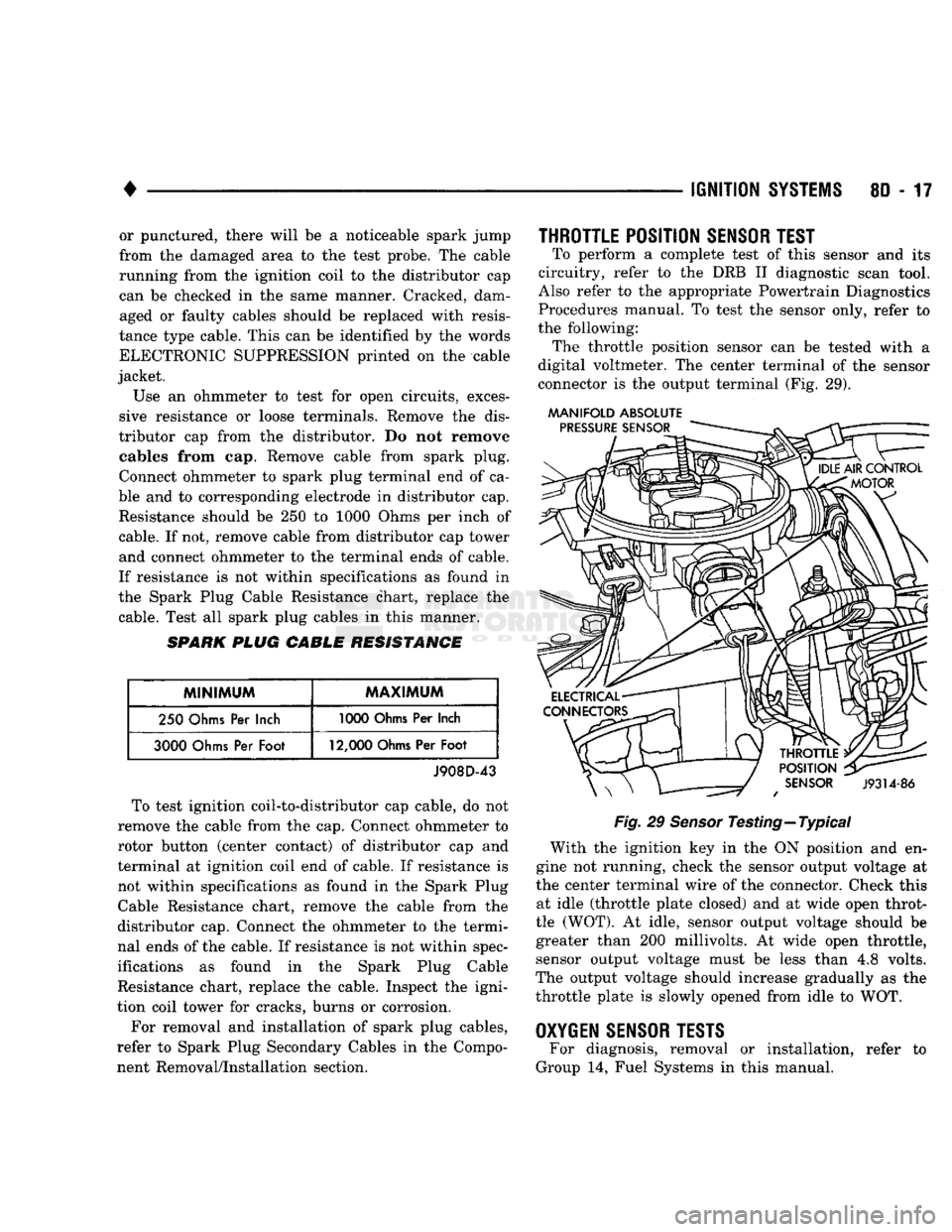
the following: The throttle position sensor
can be
tested with
a
digital voltmeter.
The
center terminal
of the
sensor
connector
is the
output terminal
(Fig. 29).
MANIFOLD ABSOLUTE
Fig.
29
Sensor
Testing—Typical With
the
ignition
key in the ON
position
and en
gine
not
running, check
the
sensor output voltage
at
the center terminal wire
of the
connector. Check this at idle (throttle plate closed)
and at
wide open throt
tle (WOT).
At
idle, sensor output voltage should
be
greater than
200
millivolts.
At
wide open throttle, sensor output voltage must
be
less than
4,8
volts.
The output voltage should increase gradually
as the
throttle plate
is
slowly opened from idle
to WOT.
OXYGEN
SENSOR
TESTS
For diagnosis, removal
or
installation, refer
to
Group
14,
Fuel Systems
in
this manual.