parking brake DODGE TRUCK 1993 Service Owner's Manual
[x] Cancel search | Manufacturer: DODGE, Model Year: 1993, Model line: TRUCK, Model: DODGE TRUCK 1993Pages: 1502, PDF Size: 80.97 MB
Page 239 of 1502
5
- 52
BRAKES
•
BRAKE
DRUM
REMOVAL
(1) Raise and support vehicle.
(2) Remove wheel and tire assembly.
(3) Remove axle shaft nuts, washers and cones.
Strike axle shaft in center with copper or dead blow
hammer to loosen retaining cones.
(4) Remove axle shaft.
(5) Remove outer hub nut.
(6)
Straighten and remove lock washer.
(7) Remove inner nut and bearing.
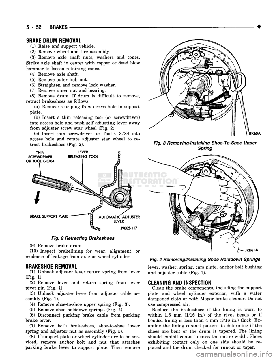
(8) Remove drum. If drum is difficult to remove,
retract brakeshoes as follows: (a) Remove rear plug from access hole in support
plate. (b) Insert a thin releasing tool (or screwdriver)
into access hole and push self adjusting lever away
from adjuster screw star wheel (Fig. 2). (c) Insert thin screwdriver, or Tool C-3784 into
access hole and rotate adjuster star wheel to re
tract brakeshoes (Fig. 2).
Fig.
2 Retracting
Brakeshoes
(9) Remove brake drum.
(10) Inspect brakelining for wear, alignment, or
evidence of leakage from axle or wheel cylinder.
BRAKESHOE
REMOVAL
(1) Unhook adjuster lever return spring from lever
(Fig. 1). (2) Remove lever and return spring from lever
pivot pin (Fig. 1). (3) Unhook adjuster lever from adjuster cable as
sembly (Fig. 1). (4) Remove shoe-to-shoe upper spring (Fig. 3).
(5)
Remove shoe holddown springs (Fig. 4).
(6)
Disconnect parking brake cable from parking
brake lever. (7) Remove both brakeshoes, shoe-to-shoe lower
spring and adjuster nut as assembly (Fig. 5). (8) If support plate or wheel cylinder are to be ser
viced, remove anchor bolt and nut that attaches
parking brake lever to support plate. Then remove
RK60A
Fig.
3 Removing/Installing
Shoe-To-Shoe
Upper
Spring
Fig.
4 Removing/Installing
Shoe
Holddown
Springs
lever, washer, spring, cam plate, anchor bolt bushing and adjuster cable (Fig. 1).
CLEANING AND INSPECTION
Clean the brake components, including the support
plate and wheel cylinder exterior, with a water dampened cloth or with Mopar brake cleaner. Do not
use compressed air. Replace the brakeshoes if the lining is worn to
within 1.5 mm (1/16 in.) of the rivet heads or if
bonded lining is less than 4 mm (3/16 in.) thick. Ex amine the lining contact pattern to determine if the
shoes are bent or the drum is tapered. The lining
should exhibit contact across the entire width. Shoes
exhibiting contact only on one side should be re
placed and the drum checked for runout or taper.
Page 240 of 1502
•
BRAKES
5 - 53
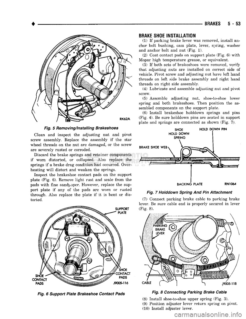
Fig.
5 Removing/installing
Brakeshoes
Clean and inspect the adjusting nut and pivot
screw assembly. Replace the assembly if the star
wheel threads on the nut are damaged, or the screw are severely rusted or corroded.
Discard the brake springs and retainer components
if worn distorted, or collapsed. Also replace the
springs if a brake drag condition had occurred. Over
heating will distort and weaken the springs.
Inspect the brakeshoe contact pads on the support
plate (Fig. 6). Remove light rust and scale from the
pads with fine sandpaper. However, replace the sup
port plate if any of the pads are worn or rusted
through. Also replace the plate if it is bent or dis
torted. Fig. 6
Support
Plate
Brakeshoe
Contact
Pads
BRAKE
SHOE
INSTALLATION
(1) If parking brake lever was removed, install an
chor bolt bushing, cam plate, lever, spring, washer
and anchor bolt and nut (Fig. 1). (2) Coat contact pads on support plate (Fig. 6) with
Mopar high temperature grease, or equivalent, (3) If both sets of brakeshoes were removed, verify
that adjusting nuts are installed on correct side of vehicle. Pivot screw and adjusting nut have left hand
threads on left side brake assembly and right hand
threads on right side assembly.
(4) Lubricate and assemble adjusting nut and pivot
screw.
(5) Assemble adjusting nut, shoe-to-shoe lower
spring and both brakeshoes. Then position the as
sembled components on the support plate.
(6) Install brakeshoe holddown springs and pins
(Fig. 4). Be sure holddown pins are seated in support
plate and springs are connected as shown (Fig. 7).
SHOE
HOLD
DOWN
PIN
HOLD DOWN
SPRING
BACKING PLATE
RN1064
Fig.
7
Holddown
Spring
And Pin Attachment (7) Connect parking brake cable to parking brake
lever. Be sure cable end is properly secured in lever
(Fig. 8).
Fig.
8
Connecting
Parking Brake Cable
(8) Install shoe-to-shoe upper spring (Fig. 3).
(9) Position adjuster lever return spring on pivot.
(10) Install adjuster lever.
Page 241 of 1502
5
- 54
BRAKES
• (11) Attach adjuster cable to adjuster lever. Be
sure cable is properly routed.
(12) Adjust brakeshoes to drum with brake gauge.
BRAKE
DRUM INSTALLATION
(1) Position drum on axle housing.
(2) Install bearing and inner nut. Adjust bearing
as described in Group 3. (3) Install locking washer and outer nut. Bend
locking washer to secure it. (4) Place new gasket on hub and install axle shaft,
cones,
lock washers and nuts. (5) Install wheel and tire assembly.
(6) Remove support stands and lower vehicle.
BRAKE
DRUM
SERVICE
BRAKE DRUM REFINISHING The brake drums can be resurfaced on a drum
lathe when necessary. Initial machining cuts should
be limited to 0.12 - 0.20 mm (0.005 - 0.008 in.) at a time as heavier feed rates can produce taper and sur
face variation. Final finish cuts of 0.025 to 0.38 mm (0.001 to 0.0015 in) are recommended and will gen
erally provide the best surface finish.
Be sure the drum is securely mounted in the lathe
before machining operations. A damper strap should always be used around the drum to reduce vibration
and avoid chatter marks.
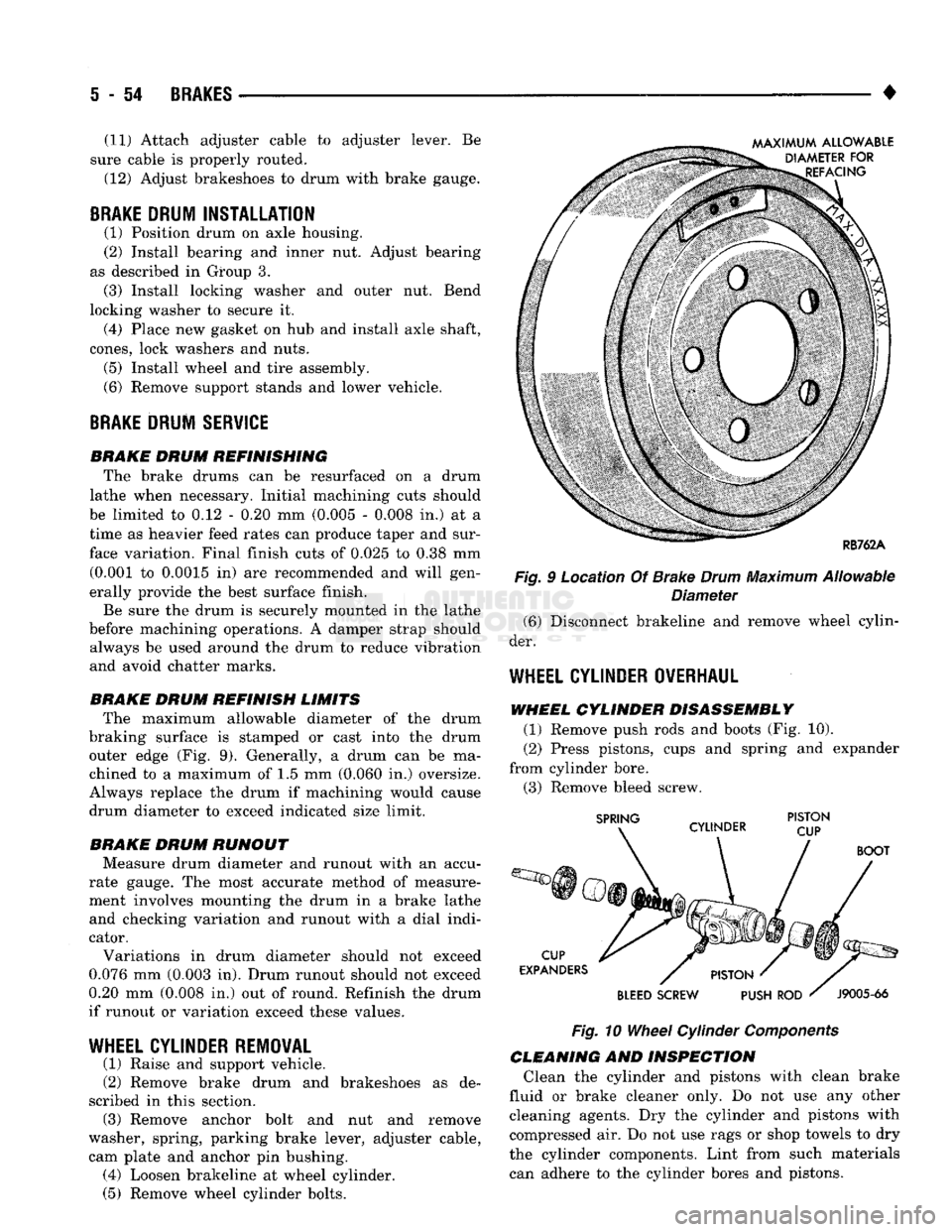
BRAKE DRUM REFINISH LIMITS The maximum allowable diameter of the drum
braking surface is stamped or cast into the drum outer edge (Fig. 9). Generally, a drum can be ma
chined to a maximum of 1.5 mm (0.060 in.) oversize.
Always replace the drum if machining would cause
drum diameter to exceed indicated size limit.
BRAKE DRUM RUNOUT Measure drum diameter and runout with an accu
rate gauge. The most accurate method of measure
ment involves mounting the drum in a brake lathe and checking variation and runout with a dial indi
cator.
Variations in drum diameter should not exceed
0.076 mm (0.003 in). Drum runout should not exceed
0.20 mm (0.008 in.) out of round. Refinish the drum
if runout or variation exceed these values.
WHEEL
CYLINDER REMOVAL
(1) Raise and support vehicle.
(2) Remove brake drum and brakeshoes as de
scribed in this section. (3) Remove anchor bolt and nut and remove
washer, spring, parking brake lever, adjuster cable, cam plate and anchor pin bushing. (4) Loosen brakeline at wheel cylinder.
(5) Remove wheel cylinder bolts. Fig. 9 Location Of Brake
Drum
Maximum Allowable
Diameter (6) Disconnect brakeline and remove wheel cylin
der.
WHEEL
CYLINDER OVERHAUL
WHEEL CYLINDER DISASSEMBLY (1) Remove push rods and boots (Fig. 10).
(2) Press pistons, cups and spring and expander
from cylinder bore. (3) Remove bleed screw.
Fig.
10
Wheel
Cylinder
Components
CLEANING AND INSPECTION Clean the cylinder and pistons with clean brake
fluid or brake cleaner only. Do not use any other cleaning agents. Dry the cylinder and pistons with
compressed air. Do not use rags or shop towels to dry
the cylinder components. Lint from such materials can adhere to the cylinder bores and pistons.
Page 242 of 1502
•
BRAKES
5 - 55 Inspect the cylinder bore. Light discoloration and
dark stains in the bore are normal and will not im
pair cylinder operation. If desired, the bore can be lightly polished but only with crocus cloth. Replace
the cylinder if the bore is scored, pitted or heavily corroded. Honing the bore to restore the surface is not recommended.
Inspect the cylinder pistons. The piston surfaces
should be smooth and free of scratches, scoring and
corrosion. Replace the pistons if worn, scored, or cor
roded. Do attempt to restore the surface by sanding or polishing.
Discard the old piston cups and the spring and ex
pander. These parts are not reusable. The original
dust boots may be reused but only if they are in good condition.
ASSEMBLING
WHEEL CYLINDER
(1) Lubricate wheel cylinder bore, pistons, piston
cups and spring and expander with ^clean brake fluid. (2) Install first piston in cylinder bore. Then in
stall cup in bore and against piston. Be sure lip of
piston cup is facing inward (toward spring and
expander) and flat side is against piston.
(3) Install spring and expanders followed by re
maining piston cup and piston.
(4) Install boots on each end of cylinder and insert
push rods in boots.
(5)
Install cylinder bleed screw.
WHEEL
CYLINDER INSTALLATION
(1) Start brakeline into cylinder.
(2) Position cylinder on support plate and install
cylinder attaching bolts. (3) Tighten brakeline fitting and cylinder attach
ing bolts. (4) Install anchor pin bushing, cam plate, adjuster
cable, parking brake lever, spring washer and anchor
bolt and nut.
(5) Install brakeshoes and brake drum as described
in this section. (6) Install axle shaft.
(7) Install wheel and tire.
(8) Remove supports and lower vehicle.
SUPPORT
PLATE REMOVAL
(1) Raise and support vehicle.
(2) Remove wheel and tire.
(3) Remove axle shaft.
(4) Remove brake drum, brake shoes and wheel
cylinder as described in this section. (5) Remove bolts/nuts attaching support plate to
axle and remove support plate.
SUPPORT PLATE INSTALLATION
(1) Transfer wheel cylinder and parking brake le
ver components to replacement support plate. (2) Position support plate on axle and install at
taching bolts/nuts. (3) Lubricate shoe contact surfaces of support plate
with Mopar multi-purpose, or high temperature bear ing grease. (4) Install brakeshoes. Adjust shoes to drum with
brake gauge. (5) Install brake drum.
(6) Install axle shaft.
(7) Install wheel and tire.
(8) Remove supports and lower vehicle.
Page 243 of 1502
5
- 56
BRAKES
•
PARKING
BRAKES
GENERAL INFORMATION
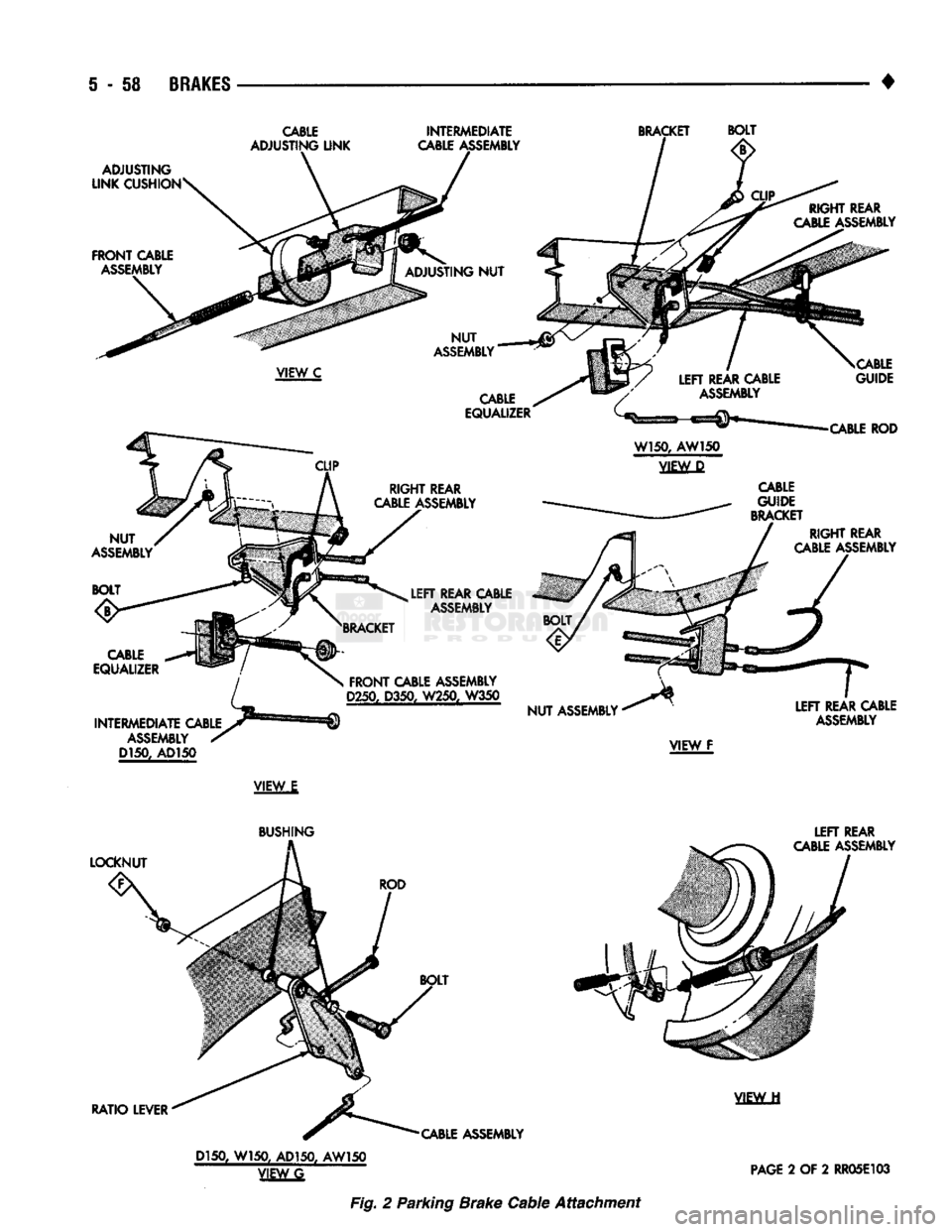
The parking brake mechanism
on AD
models
is a
three cable system operated
by a
foot pedal assembly
(Figs.
1 and 2).
The foot pedal
is
mounted
on the
driver side cowl
panel.
The
front cable
is
attached
to the
pedal assem
bly.
An
intermediate cable connects
the
front cable
to
the rear cables.
An
equalizer
and
ratio lever connect
the rear cables
to the
intermediate cable.
The
rear
cables
are
connected
to the
secondary brakeshoes
by
a lever attached
to
each shoe.
PARKING BRAKE CABLE ADJUSTMENT
(1) Adjust rear drum brakes before adjusting park
ing brake cables. (2) Release parking brakes fully.
(3) Raise vehicle.
(4) Loosen adjusting
nut on
front cable until there
is slack
in all
cables. (5) Rotate rear wheels
and
tighten cable adjusting
nut until slight drag
is
created
at
wheels.
(6)
Continue rotating rear wheels
and
loosen cable
adjusting
nut
until
all
drag
is
eliminated. (7) Back
off
cable adjusting
nut an
additional
two
full turns.
(8)
Apply parking brake several times.
(9) Release parking brakes. Then verify that rear
wheels rotate freely with
no
evidence
of
drag. (10) Lower vehicle.
REAR
CABLE REPLACEMENT
REAR CABLE
REMOVAL
(1) Release parking brakes fully.
(2) Raise vehicle.
(3) Remove adjusting
nut
from front cable.
(4) Remove rear wheels.
(5) Remove brake drums.
(6)
Remove brakeshoes
and
parking brake strut
and spring. (7) Disconnect cable from parking brake lever
on
secondary brakeshoe.
(8)
Compress cable retainer tabs
and
remove cable
from support plate.
(9) Remove cable from guides
and
retaining clips.
(10) Disconnect cable from equalizer
and
ratio
le
ver.
(11) Remove cable.
REAR CABLE
INSTALLATION
(1) Insert cable through support plate hole
and
seat cable. (2) Connect cable
to
lever
on
secondary brakeshoe.
(3) Install brakeshoes, parking brake strut
and
spring, shoe return
and
holddown springs
and
self
adjuster components.
(4)
Install cable
in
cable guide
and
install cable
re
taining clips,
if
equipped. (5) Connect cable
to
ratio lever
and
equalizer.
(6)
Adjust rear brakes
and
install brake drum
and
wheel. (7) Adjust parking brake cable.
FRONT CABLE REPLACEMENT
FRONT
CABLE
REMOVAL
(1) Remove front cable adjusting
nut.
(2) Remove clip securing cable
to
anchor bracket
and slide cable
out of
bracket.
(3) Remove retainer attaching cable
to
pedal
as
sembly frame.
(4)
Disengage cable from pedal clevis.
(5) Remove cable grommet
(or
seal) from floor
pan.
(6)
Remove front cable.
FRONT
CABLE
INSTALLATION
(1) Insert cable through floor
pan.
(2) Connect cable
to
pedal clevis
and
install cable
retainer.
(3) Seat cable grommet
(or
seal)
in
floorpan.
(4)
Route cable
to
anchor bracket
and
intermediate
cable.
(5)
Secure cable
in
anchor bracket with U-clip.
(6)
Connect cable
to
adjusting link
and
install
ca
ble adjusting
nut.
(7)
Adjust rear brakeshoes,
if
necessary.
(8) Adjust parking brake cable
as
described
in
this
section.
INTERMEDIATE
CABLE REPLACEMENT
(1) Remove adjusting
nut
from front cable.
(2) Disengage intermediate cable from ratio lever
or cable equalizer.
(3)
Remove cable.
(4)
Connect
new
cable
to
ratio lever
or
cable equal
izer.
(5)
Connect cable
to
adjusting link.
(6)
Insert front cable
in
adjusting link
and
install
cable adjusting
nut.
(7)
Adjust brakeshoes
if
necessary.
(8) Adjust parking brake cable
as
described
in
this
section.
Page 245 of 1502
i - i8
BRAKES
CABLE
INTERMEDIATE
BRACKET
BOLT
VIEW
E
Fig. 2 Parking Brake Cable Attachment
Page 249 of 1502
i - 62
BRAKES
•
Isolation/Dump
Valve Cycle Times
Activation (opening/closing) of the isolation and
dump valves is continuous during antilock operation.
The valves cycle rapidly in response to speed sensor inputs and control module signal commands. Cycle
times are measured in milliseconds.
As the demand for antilock mode brake operation
is decreased, the module deactivates the hydraulic
valve components to restore normal brake operation.
ANTILOCK
SERVICE
DIAGNOSIS
GENERAL INFORMATION An antilock system malfunction will be indicated
by illumination of the amber antilock warning lamp.
The red brake warning lamp may also illuminate.
If a problem occurs, system diagnosis should begin
with a fluid level check followed by a visual exami
nation of the system electrical and hydraulic connec
tions.
If obvious defects (low fluid, leaks, loose connections, etc.) are not evident, road test the vehi
cle.
A road test should help determine if a malfunc
tion is actually related to an antilock component.
During the road test, note if other conditions are
evident such as a low pedal, pull, grab, or similar condition. Remember that brake malfunctions such as low fluid, system leaks, parking brakes partially
applied, will also affect the antilock system. The idea
is to determine if a malfunction is actually related to
an anti-lock component.
If a road test does reveal a problem, repeat the
road test with the owner driving. Make sure the owner is not riding the brake pedal, or has forgotten
to release the parking brakes. Either situation will
generate a fault and cause the antilock light to illu
minate.
SYSTEM FAULT
CODES
The antilock control module generates flash codes
to help identify the cause of an antilock system fault. Two different control modules are used with the
1992/1993 RWAL system. A type I module is used in
some early production models. All remaining produc
tion models are equipped with a type II module. The type I and II modules are identified by the way
fault codes 9 and 11 are processed. If the vehicle has a type I module, codes 9 and 11 are not erased when
the ignition switch is turned to Off position. If the vehicle has a type II module, codes 9 and 11 are
erased when the switch is turned to Off.
FAULT CODES WITH TYPE I CONTROL
MODULE
The microprocessor in the electronic control module
has a memory and a self test feature. The self test
feature is activated whenever the ignition switch is
turned to Accessory or Run position. If a system fault is detected, the control module il
luminates the antilock light and stores the fault code
in memory. Fault codes are retained in memory even after turning the ignition switch to Off position.
FAULT CODES WITH TYPE II CONTROL
MODULE The microprocessor in the electronic control module
has a memory and a self test feature. The self test
feature is activated whenever the ignition switch is
turned to Accessory or Run position.
If a system fault is detected, the control module
will illuminate the antilock indicator lamp and store
fault codes 1 through 8, 10 and 12 through 15 in the
microprocessor memory. When one of these fault
codes is generated, the control module will retain the code after the ignition switch is turned to the Off po
sition.
When fault code 9 is generated, the code only re
mains in microprocessor memory while the ignition switch is in Run position. Turning the ignition
switch to Off position erases fault code 9. However, if
the problem still exists when the switch is turned
back to Run position, code 9 will reappear in memory after 20 seconds and the antilock light will illumi
nate once again.
When fault code 11 is generated, the antilock light
will illuminate when vehicle speed exceeds approxi mately 60.35 km/h (37.5 mph). Code 11 only remains in memory while the ignition switch is in the Run
position and the fault is present.
When the cause of a fault code 11 is corrected, the
antilock light goes off. Code 11 is erased when the ig
nition switch is turned to Off position. However, if
the problem cause still exists when the ignition switch is turned to Run position, code 11 will reap
pear when vehicle speed exceeds approximately 60.35 km/h (37.5 mph).
FAULT
CODE
CAPACITY
The microprocessor memory will store and display
only one fault code at a time. The stored code can be
displayed by grounding the RWAL diagnostic connec
tor.
FAULT
CODE
IDENTIFICATION
To determine what the fault code is, momentarily
ground the RWAL diagnostic connector and count
the number of times the amber antilock lamp flashes. Fault codes and typical malfunctions are outlined in Figure 8. Note that when a fault code is gen
erated, the red brake warning lamp will also
illuminate. The initial flash will be a long flash followed by a
number of short flashes. The long flash indicates the
beginning of the fault number sequence and the short flashes are a continuation of that sequence.
Page 330 of 1502
•
ELECTRICAL
8A - 9
ENGINE STARTER MOTOR TEST PROCEDURES
GENERAL INFORMATION
The starting system consists of an:
• ignition switch
• starter relay
• park/neutral position switch (automatic transmis sion)
• clutch switch (diesel engine-manual transmission)
• wiring harness
• battery
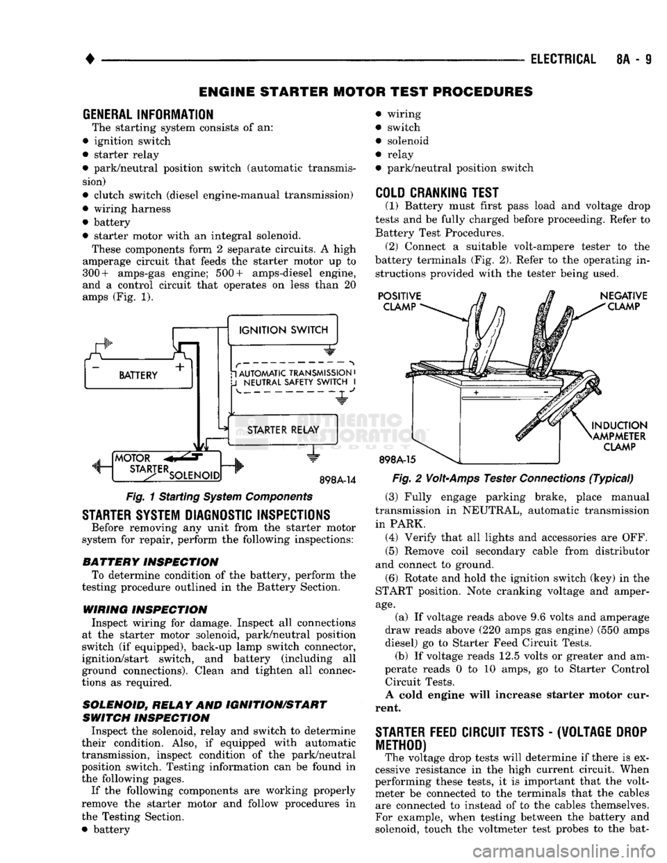
• starter motor with an integral solenoid. These components form 2 separate circuits. A high
amperage circuit that feeds the starter motor up to
300+ amps-gas engine; 500+ amps-diesel engine,
and a control circuit that operates on less than 20
amps (Fig. 1).
a.
BATTERY +
1
IGNITION
SWITCH 1 AUTOMATIC TRANSMISSION
•
J
NEUTRAL SAFETY SWITCH
I 4-
"JL"
MOTOR
m, ...
STA3-TERSOLENO,Dnlh
STARTER RELAY
1"
898A-14
Fig.
1 Starting
System
Components
STARTER SYSTEM DIAGNOSTIC INSPECTIONS
Before removing any unit from the starter motor
system for repair, perform the following inspections:
BATTERY
INSPECTION
To determine condition of the battery, perform the
testing procedure outlined in the Battery Section.
WIRING INSPECTION
Inspect wiring for damage. Inspect all connections
at the starter motor solenoid, park/neutral position
switch (if equipped), back-up lamp switch connector,
ignition/start switch, and battery (including all
ground connections). Clean and tighten all connec
tions as required.
SOLENOID, RELAY
AND
IGNITION/START
SWITCH
INSPECTION
Inspect the solenoid, relay and switch to determine
their condition. Also, if equipped with automatic
transmission, inspect condition of the park/neutral position switch. Testing information can be found in
the following pages.
If the following components are working properly
remove the starter motor and follow procedures in
the Testing Section. • battery wiring
switch
solenoid
relay
park/neutral position switch
COLD CRANKING TEST
(1) Battery must first pass load and voltage drop
tests and be fully charged before proceeding. Refer to Battery Test Procedures. (2) Connect a suitable volt-ampere tester to the
battery terminals (Fig. 2). Refer to the operating in structions provided with the tester being used.
POSITIVE
CLAMP
898A-15
NEGATIVE
CLAMP
INDUCTION
AMPMETER
CLAMP
Fig.
2
Volt-Amps
Tester
Connections
(Typical)
(3) Fully engage parking brake, place manual
transmission in NEUTRAL, automatic transmission
in PARK. (4) Verify that all lights and accessories are OFF. (5) Remove coil secondary cable from distributor
and connect to ground.
(6) Rotate and hold the ignition switch (key) in the
START position. Note cranking voltage and amper
age.
(a) If voltage reads above 9.6 volts and amperage
draw reads above (220 amps gas engine) (550 amps
diesel) go to Starter Feed Circuit Tests. (b) If voltage reads 12.5 volts or greater and am-
perate reads 0 to 10 amps, go to Starter Control Circuit Tests.
A cold engine will increase starter motor cur
rent.
STARTER
FEED
CIRCUIT TESTS
-
(W0LTAGE
DROP
METHOD)
The voltage drop tests will determine if there is ex
cessive resistance in the high current circuit. When
performing these tests, it is important that the volt meter be connected to the terminals that the cables are connected to instead of to the cables themselves.
For example, when testing between the battery and
solenoid, touch the voltmeter test probes to the bat-
Page 331 of 1502
8A
- 10
ELECTRICAL
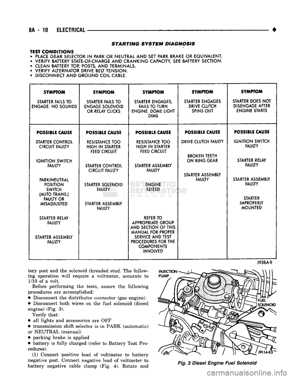
•
STARTING SYSTEM DIAGNOSIS
TEST CONDITIONS • PLACE GEAR SELECTOR
IN
PARK OR NEUTRAL AND SET PARK BRAKE
OR
EQUIVALENT. • VERIFY BATTERY STATE-OF-CHARGE AND CRANKING CAPACITY, SEE BATTERY SECTION.
• CLEAN BATTERY TOP, POSTS, AND TERMINALS.
• VERIFY ALTERNATOR DRIVE BELT TENSION.
• DISCONNECT AND GROUND COIL CABLE. SYMPTOM
SYMPTOM SYMPTOM SYMPTOM SYMPTOM
STARTER FAILS TO STARTER FAILS TO STARTER ENGAGES, STARTER ENGAGES STARTER DOES NOT
ENGAGE.
NO SOUNDS
ENGAGE
SOLENOID FAILS TO TURN DRIVE CLUTCH
DISENGAGE
AFTER
OR RELAY CLICKS ENGINE. DOME
LIGHT
SPINS
OUT
ENGINE STARTS
DIMS
POSSIBLE
CAUSE
POSSIBLE
CAUSE
POSSIBLE
CAUSE
POSSIBLE
CAUSE
POSSIBLE
CAUSE
STARTER CONTROL
RESISTANCE
TOO
RESISTANCE
TOO DRIVE CLUTCH
FAULTY
IGNITION
SWITCH
CIRCUIT
FAULTY
HIGH
IN
STARTER
HIGH
IN
STARTER
FAULTY
FEED CIRCUIT FEED CIRCUIT
BROKEN
TEETH
IGNITION
SWITCH ON RING GEAR
STARTER RELAY
FAULTY
STARTER CONTROL STARTER ASSEMBLY
FAULTY
CIRCUIT
FAULTY FAULTY
STARTER ASSEMBLY
PARK/NEUTRAL
FAULTY
STARTER ASSEMBLY
POSITION STARTER SOLENOID ENGINE
FAULTY
SWITCH
FAULTY
SEIZED
(AUTO
TRANS.) STARTER
FAULTY
OR STARTER
MISADJUSTED STARTER ASSEMBLY IMPROPERLY
FAULTY
MOUNTED
STARTER RELAY
REFER
TO
FAULTY
APPROPRIATE GROUP
AND SECTION OF THIS
MANUAL FOR PROPER
STARTER ASSEMBLY
SERVICE
AND TEST
FAULTY
PROCEDURES
FOR THE
COMPONENTS INVOLVED
J938A-9
tery post and the solenoid threaded stud. The follow
ing operation will require a voltmeter, accurate to 1/10 of a volt.
Before performing the tests, assure the following
procedures are accomplished:
•
Disconnect the distributor connector (gas engine).
•
Disconnect both wires on the fuel solenoid (diesel engine) (Fig. 3). Verify that:
•
all lights and accessories are OFF
•
transmission shift selector is in PARK (automatic)
or NEUTRAL (manual)
•
parking brake is applied
•
battery is fully charged (refer to Battery Test Pro
cedures). (1) Connect positive lead of voltmeter to battery
negative post. Connect negative lead of voltmeter to
battery negative cable clamp (Fig. 4). Rotate and
Fig.
3
Diesel
Engine
Fuel
Solenoid
Page 362 of 1502
*
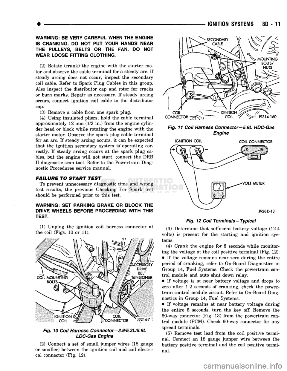
(1) Unplug the ignition coil harness connector at
the coil (Figs. 10 or 11).
Fig.
10
Coil
Harness
Connector—3.9/5.2L/5.9L
LDC-Gas
Engine
(2) Connect a set of small jumper wires (18 gauge
or smaller) between the ignition coil and coil electri
cal connector (Fig. 12).
IGNITION
SYSTEMS
80 - 11
Fig.
11
Coil
Harness
Connector—5.9L
HDC-Gas
Engine
IGNITION
COIL COIL CONNECTOR
J928D-13
Fig.
12
Coil
Terminals—Typical (3) Determine that sufficient battery voltage (12.4
volts) is present for the starting and ignition sys
tems.
(4) Crank the engine for 5 seconds while monitor
ing the voltage at the coil positive terminal (Fig. 12):
• If the voltage remains near zero during the entire
period of cranking, refer to On-Board Diagnostics in Group 14, Fuel Systems. Check the powertrain con
trol module and auto shut down relay.
• If voltage is at near battery voltage and drops to
zero after 1-2 seconds of cranking, check the power-
train control module circuit. Refer to On-Board Diag nostics in Group 14, Fuel Systems.
• If voltage remains at near battery voltage during
the entire 5 seconds, turn the key off. Remove the 60-way connector (Fig. 13) from the powertrain con
trol module (PCM). Check 60-way connector for any spread terminals.
(5) Remove test lead from the coil positive termi
nal.
Connect an 18 gauge jumper wire between the
battery positive terminal and the coil positive termi
nal.
WARNING: BE VERY CAREFUL WHEN THE ENGINE
IS
CRANKING.
DO NOT PUT
YOUR HANDS NEAR
THE PULLEYS, BELTS
OR THE FAN. DO NOT
WEAR LOOSE
FITTING
CLOTHING.
(2) Rotate (crank) the engine with the starter mo
tor and observe the cable terminal for a steady arc. If steady arcing does not occur, inspect the secondary
coil cable. Refer to Spark Plug Cables in this group.
Also inspect the distributor cap and rotor for cracks
or burn marks. Repair as necessary. If steady arcing occurs, connect ignition coil cable to the distributor
cap.
(3) Remove a cable from one spark plug.
(4) Using insulated pliers, hold the cable terminal
approximately 12 mm (1/2 in.) from the engine cylin
der head or block while rotating the engine with the starter motor. Observe the spark plug cable terminal
for an arc. If steady arcing occurs, it can be expected
that the ignition secondary system is" operating cor rectly. If steady arcing occurs at the spark plug ca
bles,
but the engine will not start, connect the DRB II diagnostic scan tool. Refer to the Powertrain Diag
nostic Procedures service manual.
FAILURE
TO START TEST To prevent unnecessary diagnostic time and wrong
test results, the previous Checking For Spark test should be performed prior to this test.
WARNING: SET PARKING BRAKE
OR
BLOCK
THE
DRIVE WHEELS BEFORE PROCEEDING
WITH
THIS
TEST.