service DODGE TRUCK 1993 Service Owner's Manual
[x] Cancel search | Manufacturer: DODGE, Model Year: 1993, Model line: TRUCK, Model: DODGE TRUCK 1993Pages: 1502, PDF Size: 80.97 MB
Page 39 of 1502
0
- 21
LUBRICATION
AND
MAINTENANCE
• SERVICE INFORMATION
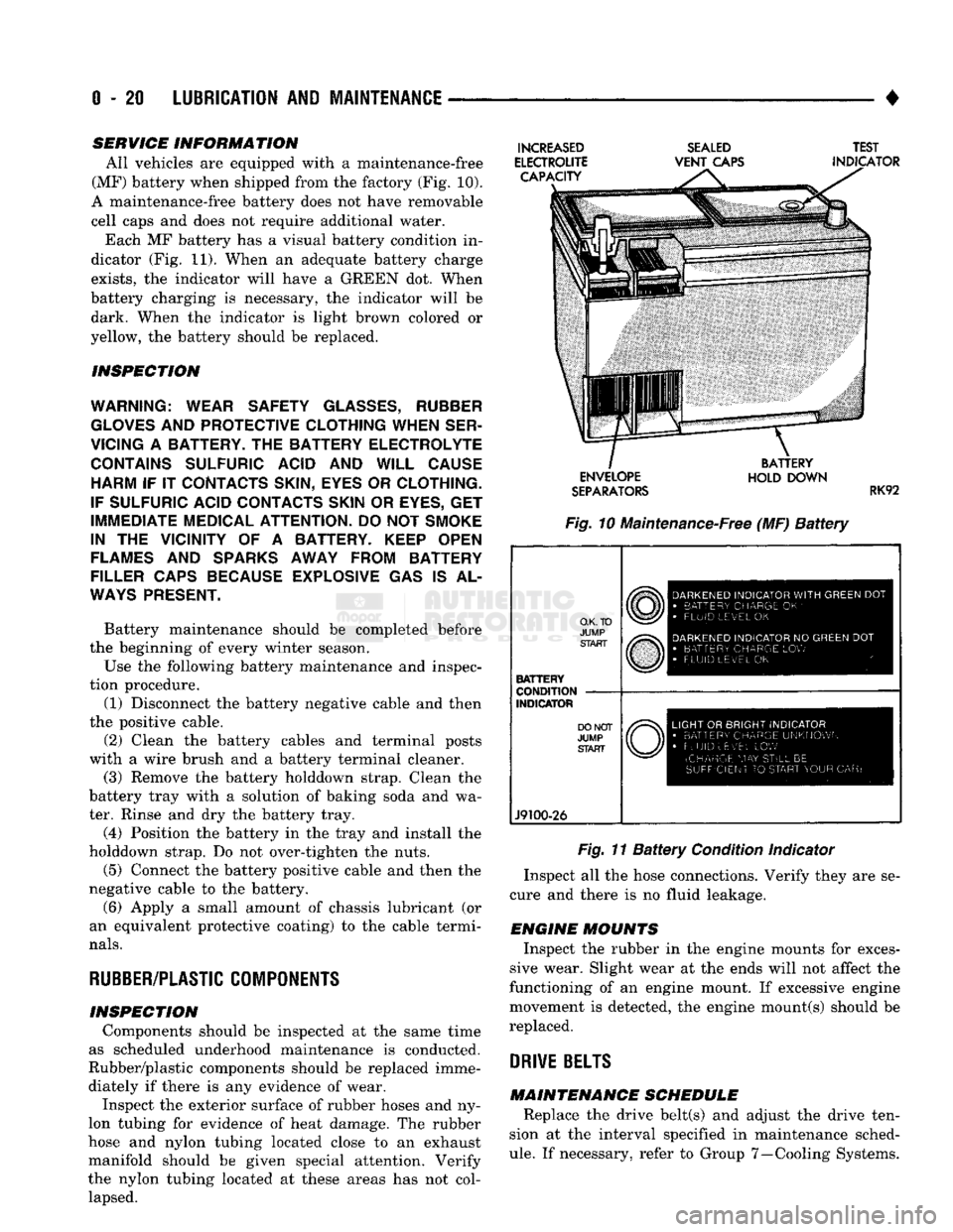
All vehicles are equipped with a maintenance-free
(MF) battery when shipped from the factory (Fig. 10).
A maintenance-free battery does not have removable
cell caps and does not require additional water. Each MF battery has a visual battery condition in
dicator (Fig. 11). When an adequate battery charge
exists,
the indicator will have a GREEN dot. When
battery charging is necessary, the indicator will be dark. When the indicator is light brown colored or
yellow, the battery should be replaced.
INSPECTION
WARNING; WEAR SAFETY
GLASSES,
RUBBER
GLOVES
AND
PROTECTIVE CLOTHING WHEN SER
VICING
A
BATTERY.
THE
BATTERY ELECTROLYTE CONTAINS SULFURIC ACID
AND
WILL CAUSE HARM
IF IT
CONTACTS SKIN, EYES
OR
CLOTHING.
IF SULFURIC ACID CONTACTS SKIN
OR
EYES,
GET
IMMEDIATE MEDICAL ATTENTION.
DO
NOT
SMOKE
IN
THE
VICINITY
OF A
BATTERY. KEEP OPEN
FLAMES
AND
SPARKS AWAY FROM BATTERY
FILLER CAPS BECAUSE EXPLOSIVE
GAS IS AL
WAYS
PRESENT.
Battery maintenance should be completed before
the beginning of every winter season.
Use the following battery maintenance and inspec
tion procedure. (1) Disconnect the battery negative cable and then
the positive cable.
(2) Clean the battery cables and terminal posts
with a wire brush and a battery terminal cleaner. (3) Remove the battery holddown strap. Clean the
battery tray with a solution of baking soda and wa
ter. Rinse and dry the battery tray.
(4) Position the battery in the tray and install the
holddown strap. Do not over-tighten the nuts.
(5) Connect the battery positive cable and then the
negative cable to the battery.
(6) Apply a small amount of chassis lubricant (or
an equivalent protective coating) to the cable termi
nals.
RUBBER/PLASTIC
COMPONENTS
INSPECTION Components should be inspected at the same time
as scheduled underhood maintenance is conducted.
Rubber/plastic components should be replaced imme diately if there is any evidence of wear. Inspect the exterior surface of rubber hoses and ny
lon tubing for evidence of heat damage. The rubber
hose and nylon tubing located close to an exhaust
manifold should be given special attention. Verify
the nylon tubing located at these areas has not col lapsed.
INCREASED
ELECTROUTE CAPACITY
SEALED
VENT
CAPS TEST
INDICATOR ENVELOPE
SEPARATORS
BATTERY
HOLD DOWN
RK92
Fig. 10 Maintenance-Free (MF)
Battery
O.K. TO
JUMP START
BATTERY
CONDITION
INDICATOR
J9100-26
DARKENED
INDICATOR
WITH
GREEN
DOT
•
BATTERY CHARGE
OK '
•
FLUID LEVEL
OK
DARKENED
INDICATOR
NO
GREEN
DOT
•
BATTERY CHARGE
LOW
FLUID LEVEL
OK
LIGHT
OR
BRIGHT INDICATOR
•
BATTERY CHARGE UNKNOWN
•
FLUID uEv'EL
LOW
(CHARGE
MAY
STILL
BE
SUFFICIENT
TO
START YOUR
CAR)
Fig. 11
Battery
Condition Indicator
Inspect all the hose connections. Verify they are se
cure and there is no fluid leakage.
ENGINE MOUNTS Inspect the rubber in the engine mounts for exces
sive wear. Slight wear at the ends will not affect the
functioning of an engine mount. If excessive engine
movement is detected, the engine mount(s) should be
replaced.
DRIVE
BELTS
MAINTENANCE SCHEDULE Replace the drive belt(s) and adjust the drive ten
sion at the interval specified in maintenance sched
ule.
If necessary, refer to Group 7—Cooling Systems.
Page 42 of 1502
•
LUBRICATION
AND
MAINTENANCE
0 - 23 GEAR SHIFTER BOOTS
Inspect the shifter boots periodically for stone and
heat damage. Replace, if necessary.
SEVERE DRIVING CONDITIONS The interval between the transmission drain and
refill maintenance should be decreased to:
• NV4500 manual transmission—every 29 000 km (18,000 miles)
• Automatic transmission—every 19 000 km (12,000
miles)
A severe driving condition includes:
• Extended operation with heavy cargo loads
• Driving in deep mud or snow
• Off-road operation (4WD)
• Trailer towing
• Operation as a commercial vehicle
• Snow plowing
MANUAL TRANSMISSIONS
INSPECTION/LUBE
OIL
LEVEL
The transmission should be checked for leaks when
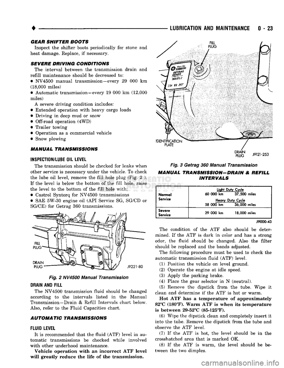
other service is necessary under the vehicle. To check
the lube oil level, remove the fill hole plug (Fig. 2 ). If the level is below the bottom of the fill hole, raise
the level to the bottom of the fill hole with:
• Castrol Syntorq for NV4500 transmissions
• SAE 5W-30 engine oil (API Service SG, SG/CD or
SG/CE) for Getrag 360 transmissions.
Fig.
2 NV4500 Manual
Transmission
DRAIN
AND
FILL
The NV4500 transmission fluid should be changed
according to the intervals listed in the Manual
Transmission—Drain & Refill Intervals chart below.
Also,
refer to the Fluid Capacities chart.
AUTOMATIC TRANSMISSIONS
FLUID
LEWEL
It is recommended that the fluid (ATF) level in au
tomatic transmissions be checked while involved
with other underhood maintenance.
Vehicle operation with an incorrect ATF level
will greatly reduce the life of the transmission.
Fig.
3 Getrag 360 Manual
Transmission
MANUAL TRANSMISSION-DRAIN & REFILL INTERVALS
Normal
Service
Light
Duty
Cycle
60 000
km
37,500
miles
Heavy
Duty
Cycle
58 000
km
36,000
miles
Severe
Service
29 000
km
18,000
miles
J9000-43
The condition of the ATF also should be deter
mined. If the ATF is dark in color and has a strong odor, the fluid should be changed. Also the filter should be replaced and the bands adjusted.
The following procedure must be used to check the
automatic transmission fluid (ATF) level.
(1) Position the vehicle on level ground.
(2) Operate the engine at idle speed.
(3) Apply the parking brake.
(4) Place the gear selector in N (neutral).
(5) Remove the dipstick from the tube. Wipe it
clean and determine if the ATF is hot or warm.
Hot ATF has a temperature of approximately
82°C (180°F). Warm ATF is when its temperature
is between 29-52°C (85-125°F). (6) Wipe the dipstick clean and completely insert it
into the tube. Remove the dipstick from the tube and
observe the ATF level.
(7) If the ATF is hot, the level should be in the
crosshatched area that is marked OK.
(8) If the ATF is warm, the level should be be
tween the two dimples.
Page 43 of 1502
0
- 24
LUBRICATION
AND
MAINTENANCE
•
CAUTION:
Do not
overfill
the
transmission.
(9) Adjust
the
level
of the ATF
accordingly.
It
is
important
to use the
correct fluid
in an
automatic transmission. MOPAR®ATF PLUS
(ATF Type
7176)
should
be
used. Dexron®
II
ATF
can be
used
if the
recommended fluid
is not
available,
(10) Insert
the
dipstick into
the
tube.
DRAIN, FILTER CHANGE, BAND ADJUSTMENT AND REFILL
The chart below lists
the
intervals
at
which
the
transmission should
be
serviced. Also, refer
to the
Fluid Capacities chart
for
fill capacity.
AUTOMATIC TRANSMISSION SERVICE
IN-
TERVALS
Normal
Usage
Light
Duty
Cycle
60 000
km
37,500
miles
Heavy
Duty
Cycle
38
000 km 24,000
miles
Severe
Usage
19 000 km 12,000
miles
J9100-19
It
is
very important
to use the
correct fluid
in
an automatic transmission. MOPAR®ATF PLUS
(ATF Type
7176)
should
be
used.
An
equivalent
Dexron®
II ATF
could
be
used only
if the
recom
mended fluid
is not
available.
The torque converter does
not
have
a
drain plug.
No attempt should
be
made
to
drain
the
converter.
Refer
to
Group
21
—Transmissions
for
transmission
drain
and
refill procedures.
TRANSFER
CASE
(4WD
VEHICLES)
INSPECTION The NP205
and
NP241 transfer cases fluid level
should
be
checked whenever maintenance
is
neces
sary under
the
vehicle.
FLUID
LEVEL
The vehicle must
be
level when
the
fluid level
is checked.
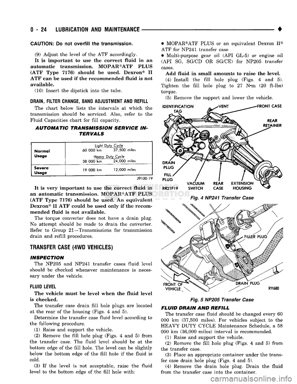
The transfer case drain fill hole plugs
are
located
at
the
rear
of the
housing (Figs.
4 and 5).
Determine
the
transfer case fluid level according
to
the following procedure.
(1) Raise
and
support
the
vehicle.
(2) Remove
the
fill hole plug (Figs.
4 and 5)
from
the transfer case.
The
fluid level should
be at the
bottom edge
of the
fill hole.
The
level
can be
slightly
below
the
bottom edge
of the
fill hole
if the
fluid
is
cold.
(3)
If the
level
is not
acceptable, raise
the
fluid
level
to the
bottom edge
of the
fill hole with: • MOPAR®ATF PLUS
or an
equivalent Dexron
II®
ATF
for
NP241 transfer case
• Multi-purpose gear
oil (API GL-5) or
engine
oil
(API
SG,
SG/CD
OR
SG/CE)
for
NP205 transfer
cases.
Add fluid
in
small amounts
to
raise
the
level. (4) Install
the
fill hole plug (Figs.
4 and 5).
Tighten
the
fill hole plug
to 27 N-m (20
ft-lbs) torque.
(5) Remove
the
support
and
lower
the
vehicle.
Fig.
4
HP241 Transfer
Case
Fig.
5
NP205 Transfer
Case
FLUID DRAIN
AND
REFILL The transfer case fluid should
be
changed every
60
000
km
(37,500 miles).
For
vehicles subject
to the
HEAVY DUTY CYCLE Maintenance Schedule,
a 58
000
km
(36,000 miles) interval
is
recommended.
(1) Raise
and
support
the
vehicle.
(2) Remove
the
fill hole plug (Figs.
4 and 5)
from
the transfer case. (3) Place
an
appropriate container under
the
trans
fer case drain hole plug (Figs.
4 and 5).
(4) Remove
the
drain hole plug. Drain
the
fluid
from
the
transfer case into
the
container.
Page 45 of 1502
0
- 26
LUBRICATION
AND
MAINTENANCE
•
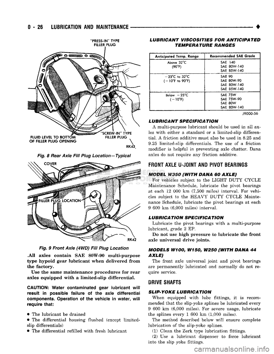
"PRESS-IN"
TYPE FILLER PLUG
RK43t
Fig.
8
Rear Axle Fill Plug Location—Typical Fig.
9
Front Axle (4
WD)
Fill Plug Location
.All axles contain
SAE
80W-90 multi-purpose
type hypoid gear lubricant when delivered from
the factory.
Use
the
same maintenance procedures
for
rear
axles equipped with
a
limited-slip differential.
CAUTION:
Water
contaminated
gear
lubricant
will
result
in
possible
failure
of the
axle
differential
components.
Operation
of the
vehicle
in
water,
will
require
that:
•
The
lubricant
be
drained
•
The
differential housing flushed (except limited- slip differentials)
•
The
differential refilled with fresh lubricant
LUBRICANT
VISCOSITIES
FOR
ANTICIPATED
TEMPERATURE
RANGES
Anticipated Temp.
Range
Recommended
SAE
Grade
Above
32°C
SAi
140
(90°F)
SAE
SOW-140
(90°F)
S\E
85W-140
-
23°C to 32°C
SAE
90
(-10°F
to 90°F)
SAE
80W-90
(-10°F
to 90°F)
SAE
80W-140
oAE
85W-140
(ielow
-23°C
SAE
75W
(-10°F)
SAE
75W-90
(-10°F)
SAE
80W
SAE
80W-I40
J9000-56
LUBRICANT
SPECIFICA
TION
A multi-purpose lubricant should
be
used
in all ax
les with either
a
standard
or a
limited-slip differen
tial.
A
friction additive must also
be
used
in 8.25 and
9.25 limited-slip differentials.
The use of a
friction
modifier
is
helpful
in
preventing axle chatter. Dana axles
do not
require
any
friction additive.
FRONT
AXLE
U-JOINT
AND
PIVOT
BEARINGS
MODEL
W350 (WITH
DANA
60
AXLE) For vehicles subject
to the
LIGHT DUTY CYCLE
Maintenance Schedule, lubricate
the
pivot bearings at each
12 000 km
(7,500 miles) interval.
For
vehi
cles subject
to the
HEAVY DUTY CYCLE Mainte
nance Schedule, lubricate
the
pivot bearings
at
each
9
600 km
(6,000 miles) interval.
LUBRICATION
SPECIFICATION
Lubricate
the
pivot bearings with
a
multi-purpose
lubricant, grade
2 EP.
Do
not use
high pressure
to
lubricate
the
front
axle universal drive joints.
MODELS
WiOO,
W150,
W250 (WITH
DANA
44
AXLE)
The front axle universal joint
and
pivot bearings
are permanently lubricated
and
normally
do not re
quire service.
DRIVE
SHAFTS
SLIP-YOKE
LUBRICATION
When equipped with lube fittings,
it is
recom
mended that
the
slip-yoke splines
be
lubricated every
9
600 km
(6,000 miles).
For
severe usage, lubricate
the splines every
1 600 km
(1,000 miles).
The method described below will ensure complete
lubrication
of the
slip-yoke splines.
(1)
Clean
the
Zerk type lubrication fittings.
(2)
Use a
lubricant dispenser
to
force lubricant
into
the
slip yoke fittings.
Page 46 of 1502
•
LUBRICATION
AND
MAINTENANCE
0 - 27 (3) Continue lubricating until it appears at the
pressure relief hole in the expansion plug located at the slip-yoke end.
(4) Cover the pressure relief hole with a finger.
Continue to force lubricant into the fitting until it
appears at the slip-yoke seal.
U-JOINT
INSPECTION
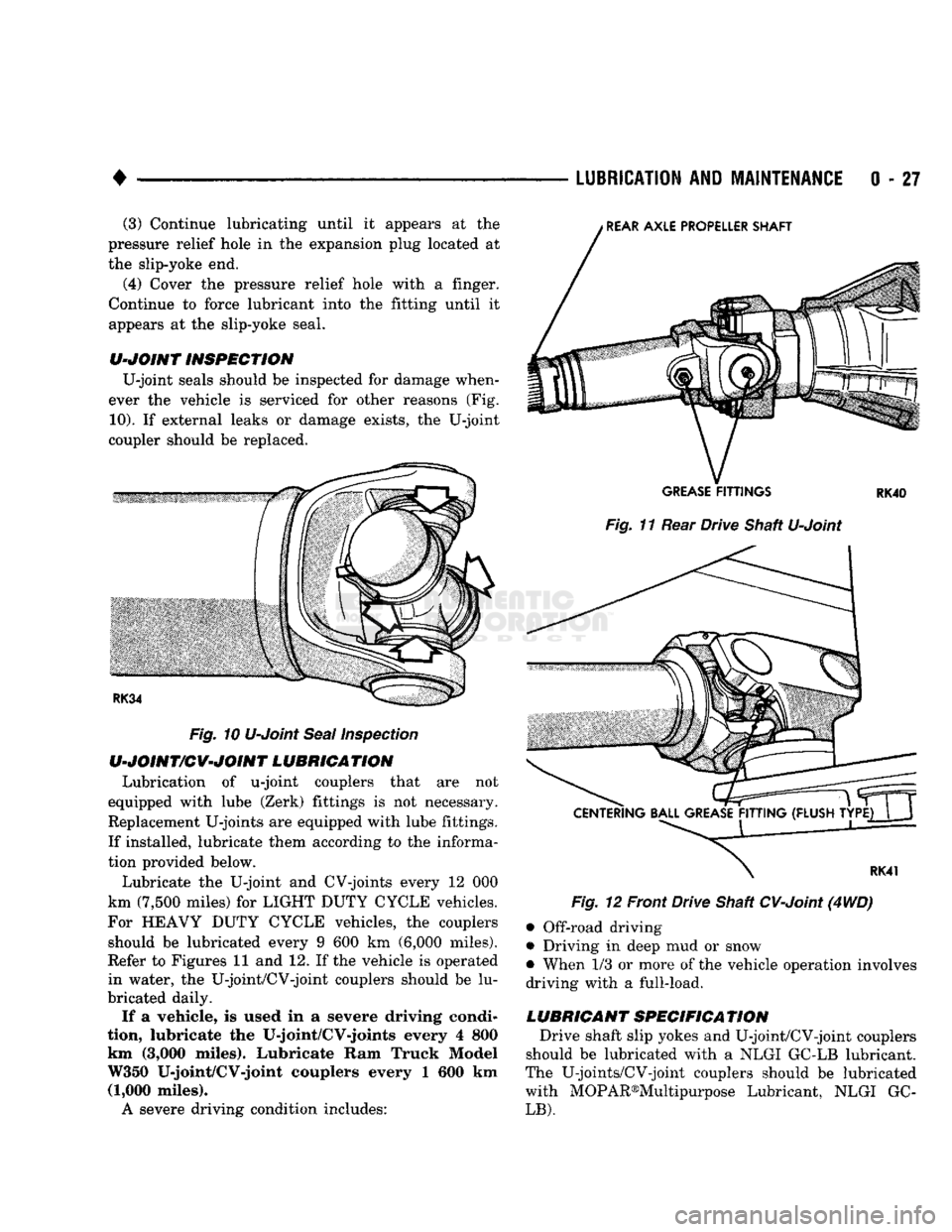
U-joint seals should be inspected for damage when
ever the vehicle is serviced for other reasons (Fig.
10).
If external leaks or damage exists, the U-joint
coupler should be replaced.
Fig.
10 U-Joint
Seal
Inspection
U-JOINT/CV-JOINT
LUBRICATION
Lubrication of u-joint couplers that are not
equipped with lube (Zerk) fittings is not necessary.
Replacement U-joints are equipped with lube fittings.
If installed, lubricate them according to the informa tion provided below.
Lubricate the U-joint and CV-joints every 12 000
km (7,500 miles) for LIGHT DUTY CYCLE vehicles.
For HEAVY DUTY CYCLE vehicles, the couplers should be lubricated every 9 600 km (6,000 miles).
Refer to Figures 11 and 12. If the vehicle is operated
in water, the U-joint/CV-joint couplers should be lu
bricated daily. If a vehicle, is used in a severe driving condi
tion,
lubricate the U-joint/CV-joints every 4 800
km (3,000 miles). Lubricate Ram Truck Model W350 U-joint/CV-joint couplers every 1 600 km
(1,000 miles). A severe driving condition includes:
GREASE
FITTINGS
RK40
Fig.
11 Rear Drive Shaft U-Joint
Fig.
12 Front Drive Shaft
CV-Joint
(4WD)
• Off-road driving
• Driving in deep mud or snow
• When 1/3 or more of the vehicle operation involves
driving with a full-load.
LUBRICANT
SPECIFICATION
Drive shaft slip yokes and U-joint/CV-joint couplers
should be lubricated with a NLGI GC-LB lubricant.
The U-joints/CV-joint couplers should be lubricated with MOPAR®Multipurpose Lubricant, NLGI GC-
LB).
Page 48 of 1502
•
LUBRICATION
AND
MAINTENANCE
0 - 29
POWER STEERING SYSTEM
SERVICE SCHEDULE
FLUID
LEWEL
WARNING.
THE
POWER
STEERING
FLUID LEVEL
SHOULD
ALWAYS
BE
CHECKED
WITH THE EN
GINE
OFF TO
PREVENT
PERSONAL
INJURY.
The power steering fluid should be checked when
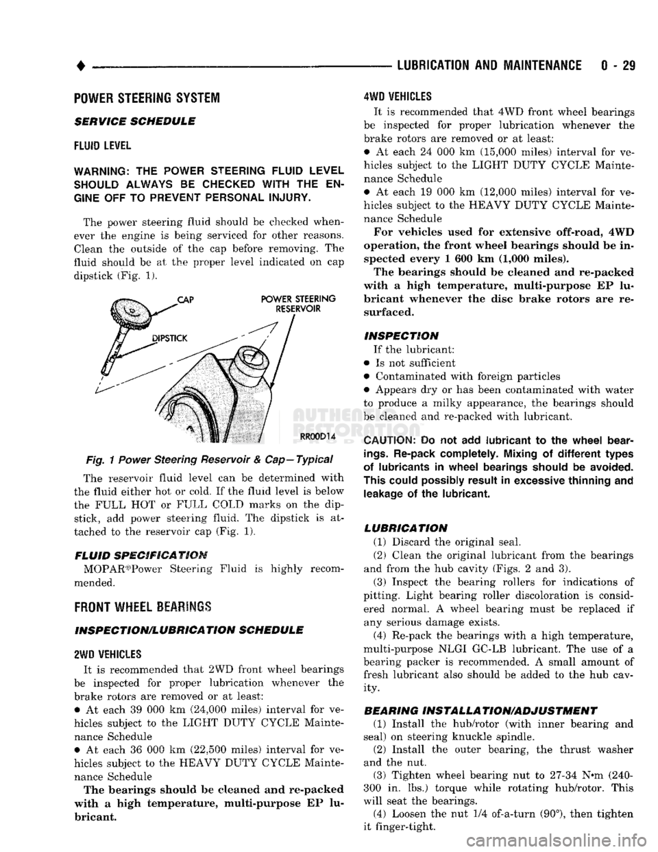
ever the engine is being serviced for other reasons. Clean the outside of the cap before removing. The
fluid should be at the proper level indicated on cap dipstick (Fig. 1).
Fig.
1
Power
Steering Reservoir & Cap—Typical
The reservoir fluid level can be determined with
the fluid either hot or cold. If the fluid level is below
the FULL HOT or FULL COLD marks on the dip stick, add power steering fluid. The dipstick is at
tached to the reservoir cap (Fig. 1).
FLUID SPECIFICATION MOPAR03)Power Steering Fluid is highly recom
mended.
FRONT
WHEEL BEARINGS
INSPECTION/LUBRICATION SCHEDULE
2WD
VEHICLES
It is recommended that 2WD front wheel bearings
be inspected for proper lubrication whenever the
brake rotors are removed or at least: • At each 39 000 km (24,000 miles) interval for ve
hicles subject to the LIGHT DUTY CYCLE Mainte nance Schedule • At each 36 000 km (22,500 miles) interval for ve
hicles subject to the HEAVY DUTY CYCLE Mainte nance Schedule The bearings should be cleaned and re-packed
with a high temperature, multi-purpose EP lu
bricant.
4WD
VEHICLES
It is recommended that 4WD front wheel bearings
be inspected for proper lubrication whenever the
brake rotors are removed or at least:
• At each 24 000 km (15,000 miles) interval for ve
hicles subject to the LIGHT DUTY CYCLE Mainte nance Schedule
• At each 19 000 km (12,000 miles) interval for ve
hicles subject to the HEAVY DUTY CYCLE Mainte nance Schedule
For vehicles used for extensive off-road, 4WD
operation, the front wheel bearings should be in spected every 1 600 km (1,000 miles).
The bearings should be cleaned and re-packed
with a high temperature, multi-purpose EP lu
bricant whenever the disc brake rotors are re surfaced.
INSPECTION If the lubricant:
• Is not sufficient
• Contaminated with foreign particles
• Appears dry or has been contaminated with water
to produce a milky appearance, the bearings should
be cleaned and re-packed with lubricant.
CAUTION:
Do not add
lubricant
to the
wheel
bear
ings.
Re-pack completely. Mixing
of
different
types
of lubricants
in
wheel
bearings should
be
avoided.
This could possibly result
in
excessive thinning
and
leakage
of the
lubricant.
LUBRICATION (1) Discard the original seal.
(2) Clean the original lubricant from the bearings
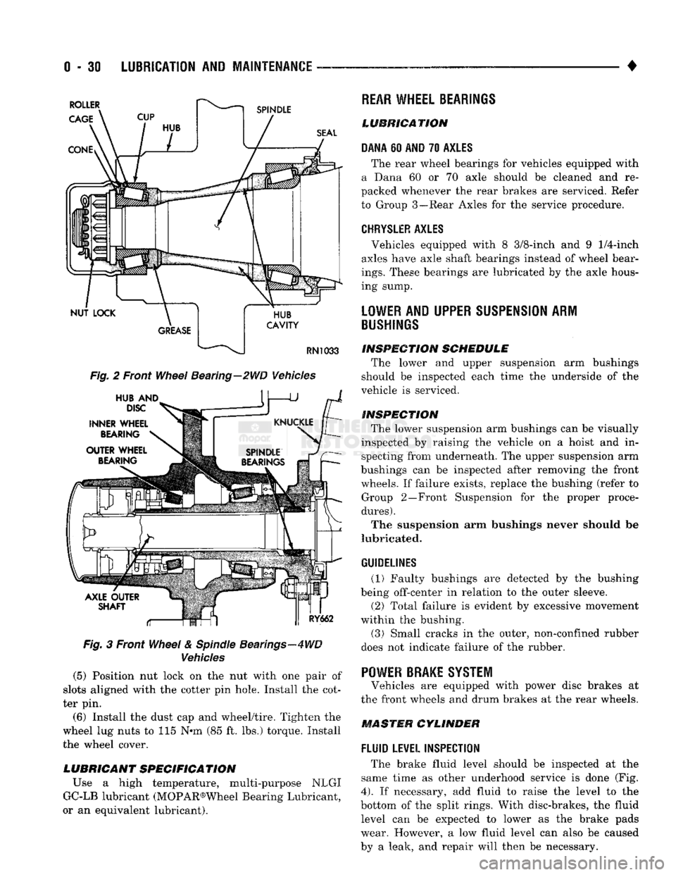
and from the hub cavity (Figs. 2 and 3).
(3) Inspect the bearing rollers for indications of
pitting. Light bearing roller discoloration is consid ered normal. A wheel bearing must be replaced if any serious damage exists.
(4) Re-pack the bearings with a high temperature,
multi-purpose NLGI GC-LB lubricant. The use of a
bearing packer is recommended. A small amount of fresh lubricant also should be added to the hub cav ity.
BEARING INSTALLA TION/ADJUSTMENT (1) Install the hub/rotor (with inner bearing and
seal) on steering knuckle spindle.
(2) Install the outer bearing, the thrust washer
and the nut.
(3) Tighten wheel bearing nut to 27-34 N^m (240-
300 in. lbs.) torque while rotating hub/rotor. This
will seat the bearings.
(4) Loosen the nut 1/4 of-a-turn (90°), then tighten
it finger-tight.
Page 49 of 1502
0 - 30
LUBRICATION
AND
MAINTENANCE
— - •
Fig.
2 Front
Wheel
Bearing—2WD Vehicles
Fig.
3 Front
Wheel
&
Spindle
Bearings—4WD
Vehicles
(5) Position nut lock on the nut with one pair of
slots aligned with the cotter pin hole. Install the cot
ter pin.
(6) Install the dust cap and wheel/tire. Tighten the
wheel lug nuts to 115 N*m (85 ft. lbs.) torque. Install
the wheel cover.
LUBRICANT SPECIFICATION
Use a high temperature, multi-purpose NLGI
GC-LB lubricant (MOPAR®Wheel Bearing Lubricant,
or an equivalent lubricant).
REAR
WHEEL BEARINGS
LUBRICATION
DANA
60
AND
70
AXLES
The rear wheel bearings for vehicles equipped with
a Dana 60 or 70 axle should be cleaned and re
packed whenever the rear brakes are serviced. Refer
to Group 3—Rear Axles for the service procedure.
CHRYSLER
AXLES
, Vehicles equipped with 8 3/8-inch and 9
1/4-inch
axles have axle shaft bearings instead of wheel bear
ings.
These bearings are lubricated by the axle hous
ing sump.
LOWER
AND UPPER
SUSPENSION
ARM
BUSHINGS
INSPECTION
SCHEDULE
The lower and upper suspension arm bushings
should be inspected each time the underside of the
vehicle is serviced.
INSPECTION
The lower suspension arm bushings can be visually
inspected by raising the vehicle on a hoist and in specting from underneath. The upper suspension arm
bushings can be inspected after removing the front wheels. If failure exists, replace the bushing (refer to Group 2—Front Suspension for the proper proce
dures).
The suspension arm bushings never should be
lubricated.
GUIDELINES
(1) Faulty bushings are detected by the bushing
being off-center in relation to the outer sleeve.
(2) Total failure is evident by excessive movement
within the bushing.
(3)
Small cracks in the outer, non-confined rubber
does not indicate failure of the rubber. '
POWER BRAKE SYSTEM
Vehicles are equipped with power disc brakes at
the front wheels and drum brakes at the rear wheels.
MASTER CYLINDER
FLUID
LEVEL INSPECTION
The brake fluid level should be inspected at the
same time as other underhood service is done (Fig.
4).
If necessary, add fluid to raise the level to the
bottom of the split rings. With disc-brakes, the fluid level can be expected to lower as the brake pads
wear. However, a low fluid level can also be caused
by a leak, and repair will then be necessary.
Page 52 of 1502
•
LUBRICATION
AND
MAINTENANCE
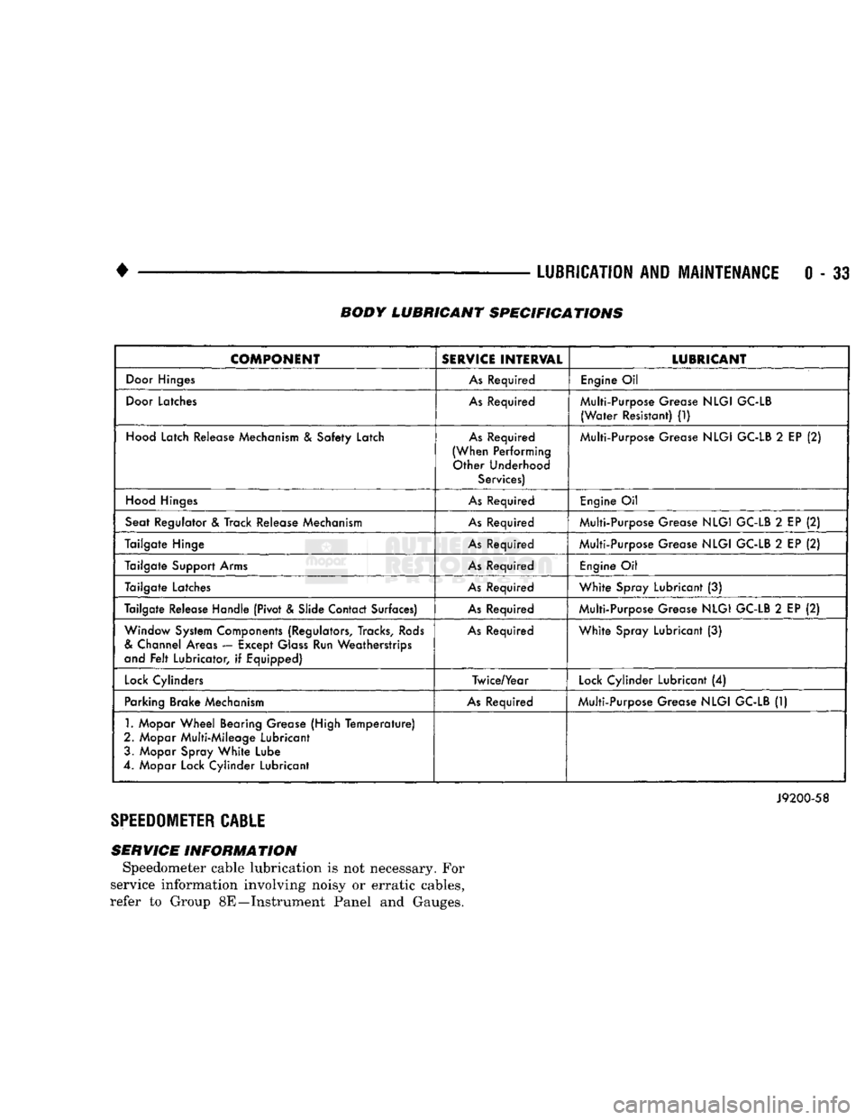
0 - 33 BODY LUBRICANT SPECIFICATIONS
COMPONENT
SERVICE
INTERVAL
LUBRICANT
Door
Hinges
As
Required
Engine
Oil
Door
Latches
As
Required Multi-Purpose Grease
NLGI
GC-LB
(Water
Resistant)
(1)
Hood
Latch Release Mechanism
&
Safety Latch
As
Required
(When Performing Other Underhood Services) Multi-Purpose Grease
NLGI
GC-LB
2
EP
(2)
Hood
Hinges
As
Required
Engine
Oil
Seat Regulator
&
Track Release Mechanism
As
Required Multi-Purpose Grease
NLGI
GC-LB
2
EP
(2)
Tailgate Hinge
As
Required Multi-Purpose Grease
NLGI
GC-LB
2
EP
(2)
Tailgate Support Arms
As
Required
Engine
Oil
Tailgate Latches
As
Required
White
Spray Lubricant
(3)
Tailgate Release Handle (Pivot & Slide Contact Surfaces)
As
Required Multi-Purpose Grease
NLGI
GC-LB
2
EP
(2)
Window System Components (Regulators, Tracks,
Rods
&
Channel Areas — Except
Glass
Run Weatherstrips
and
Felt
Lubricator,
if
Equipped)
As
Required
White
Spray Lubricant
(3)
Lock
Cylinders Twice/Year
Lock
Cylinder Lubricant
(4)
Parking Brake Mechanism
As
Required Multi-Purpose Grease
NLGI
GC-LB
(1)
1.
Mopar
Wheel
Bearing Grease (High
Temperature)
2. Mopar Multi-Mileage Lubricant 3. Mopar Spray
White
Lube
4. Mopar Lock Cylinder Lubricant
J9200-58
SPEEDOMETER
CABLE
SERVICE INFORMATION Speedometer cable lubrication is not necessary. For
service information involving noisy or erratic cables,
refer to Group 8E—Instrument Panel and Gauges.
Page 54 of 1502
•
FRONT SUSPENSION
AND
AXLE
2 - 1
CONTENTS
page
FRONT SUSPENSION—2WD VEHICLES
......
7
FRONT SUSPENSION—4WD VEHICLES
14
FRONT WHEEL
ALIGNMENT
...............
3
GENERAL INFORMATION
1
page
MODEL
44
FRONT AXLE
17
MODEL
80
FRONT AXLE
49
TORQUE SPECIFICATIONS
75
GENERAL
INFORMATION
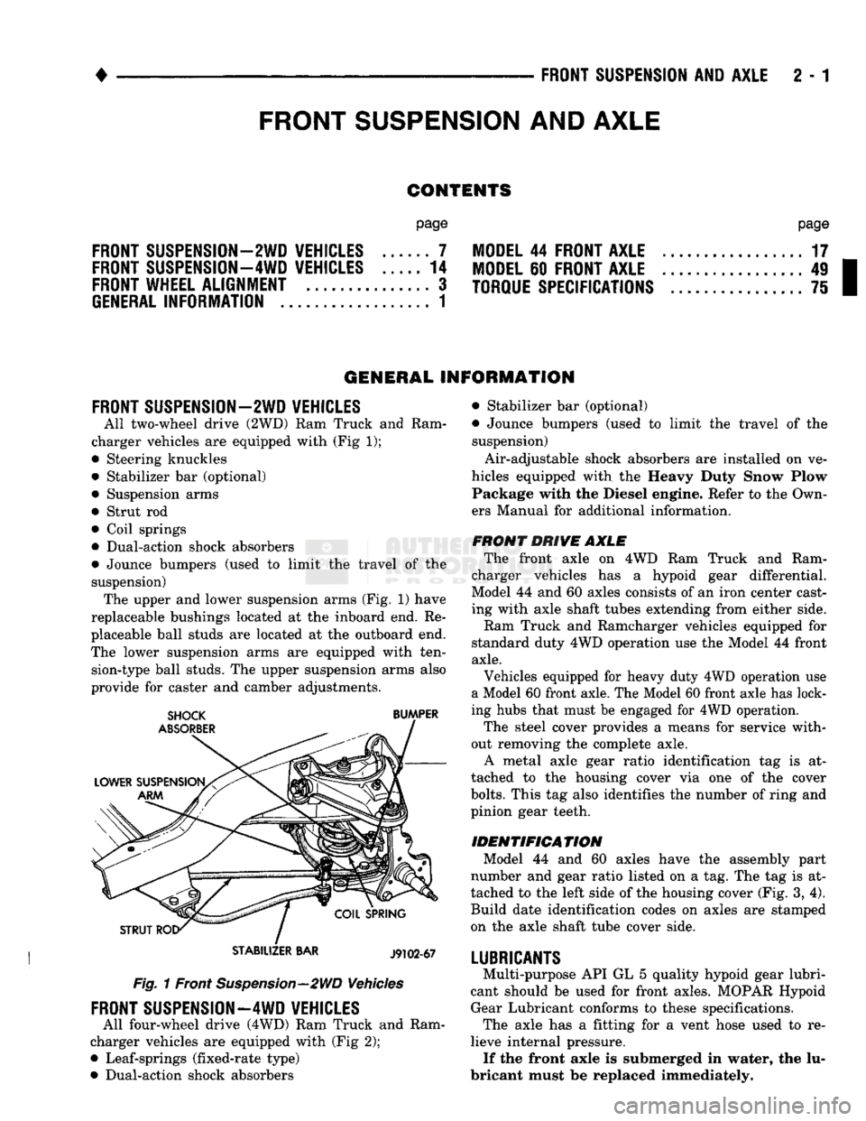
FRONT SUSPENSION—2WD VEHICLES
All two-wheel drive (2WD)
Ram
Truck
and
Ram
charger vehicles
are
equipped with (Fig
1);
• Steering knuckles
• Stabilizer
bar
(optional) • Suspension arms
• Strut
rod
• Coil springs
• Dual-action shock absorbers
• Jounce bumpers (used
to
limit
the
travel
of the
suspension) The upper and lower suspension arms (Fig.
1)
have
replaceable bushings located
at the
inboard end.
Re
placeable ball studs
are
located
at
the
outboard end.
The lower suspension arms
are
equipped with ten sion-type ball studs. The upper suspension arms also
provide
for
caster
and
camber adjustments.
STABILIZER
BAR
J9102-67
Fig. 1 Front Suspension—2WD Vehicles
FRONT SUSPENSION—4WD VEHICLES
All four-wheel drive (4WD) Ram Truck
and
Ram
charger vehicles
are
equipped with (Fig
2);
• Leaf-springs (fixed-rate type)
• Dual-action shock absorbers • Stabilizer
bar
(optional)
• Jounce bumpers (used
to
limit
the
travel
of the
suspension)
Air-adjustable shock absorbers
are
installed
on
ve
hicles equipped with
the
Heavy Duty Snow Plow Package with
the
Diesel engine. Refer
to
the Own
ers Manual
for
additional information.
FRONT DRIVE AXLE The front axle
on 4WD Ram
Truck
and
Ram
charger vehicles
has a
hypoid gear differential.
Model
44
and
60
axles consists
of
an iron center cast
ing with axle shaft tubes extending from either side.
Ram Truck
and
Ramcharger vehicles equipped
for
standard duty 4WD operation use
the
Model
44
front
axle.
Vehicles equipped
for
heavy duty 4WD operation
use
a Model 60 front axle. The Model 60 front axle has lock
ing hubs that must
be
engaged
for
4WD operation.
The steel cover provides
a
means
for
service with
out removing
the
complete axle. A metal axle gear ratio identification
tag is at
tached
to the
housing cover
via one of the
cover
bolts.
This
tag
also identifies
the
number
of
ring and
pinion gear teeth.
IDENTIFICATION Model
44 and 60
axles have
the
assembly part
number
and
gear ratio listed
on a
tag. The
tag
is at
tached
to
the
left side
of
the housing cover (Fig.
3,
4).
Build date identification codes
on
axles
are
stamped
on
the
axle shaft tube cover side.
LUBRICANTS
Multi-purpose API
GL
5
quality hypoid gear lubri
cant should
be
used
for
front axles. MOPAR Hypoid Gear Lubricant conforms
to
these specifications. The axle
has a
fitting
for a
vent hose used
to re
lieve internal pressure. If the front axle
is
submerged
in
water,
the
lu
bricant must
be
replaced immediately.
FRONT
SUSPENSION
AND
AXLE
Page 57 of 1502
2 - 4 FRONT SUSPENSION AND AXLE
•
I
FRONT END
|
|*?£E;
LOOSE
OR WORN
FRONT WHEEL
BEARINGS
LOOSE
C
SHOCKS
MOUNTir
WAR
SHOCK
A )RWORN
JSORBER
nIG
HARD-
E
OR
BSORBER
EXCiSSIVE
PLAY
STEERING
LINKAGE
LOOSE
OR WORN
FRONT WHEEL
BEARINGS
LOOSE
C
STEERINC
SHAFT
C
)RWORN
7
COLUMN
OUPLING
DIFFICULT
STEERING
LOOSE
OR WORN
WHEEL BEARINGS
TIRE/V
OUT OF
f
VHEEL
JA
LANCE
LOW OR UNEVEN
TIRE
AIR
PRESSURE
LO(
WHEEL B
DSE
EARINGS
LOW OR UNEVEN
TIRE AIR
PRESSURE
1vsnciEi
I
1
PULLS
TO I
I
|
ONE SIDE
j
LOOSE,
WORN
OR
GLAZED
P/S PUMP BELT LOW OR UNEVEN
TIRE PRESSURE
WHILE BR
REFE
BRAKES
AKING—
R
TO
SERVICE
LOOSE
STEERING
GEAR-TO-FRAME
RAIL BOLTS
LOOSE
STEERING
GEAR-TO-FRAME
RAIL BOLTS UNEVEN TIRE TREAD
WEAR,
OR
EX
CESSIVELY
WORN TIRE TREAD
BROKEN
OR WEAK
REAR
SPRING LOW
POWER STEERING
FLUID
LEVEL
BROKEN
OR WEAK
REAR
SPRING
WORN
UPPER
SUSPENSION ARM BUSHINGS WORN TIE-
ROD
END
BALL
STUDS WORN TIE-
ROD
END
BALL
STUDS
SHOCK
ABSORBER
NOT FUNCTIONING
CORRECTLY
LACK
OF ASSIST
FROM POWER
STEERING
PUMP
LOOSE
OR WORN
SUSPENSION
BUSHINGS
WORN LOWER
SUSPENSION
ARM
PIVOT
BUSHINGS INCORRECT
STEERING
GEAR ADJUSTMENT
LOOSE
OR WORN
SUSPENSION
ARM
BUSHINGS
INCORRECT
STEERING
GEAR ADJUSTMENT
BALL
STUDS
REQUIRE
LUBRICATION INCORRECT FRONT
WHEEL ALIGNMENT (EITHER CASTER OR CAMBER)
LOOSE
LOWER
SUSPENSION
ARM
LOOSE
OR WORN
UPPER
SUSPENSION ARM BALL STUDS
LOOSE
OR WORN
SUSPENSION
ARM
BUSHINGS
STEERING
GEAR
LUBRICANT LEVEL LOW
WORN ISOLATOR
PAD
BETWEEN COIL
SPRING
AND
FRAME
BRACKET INCORRECT FRONT-
WHEEL ALIGNMENT (PARTICULARLY
CASTER)
INCORRECT FRONT
WHEEL ALIGNMENT INCORRECT
STEERING
GEAR ADJUSTMENT
STEERING
GEAR
MALFUNCTION
INCORRECT FRONT
WHEEL ALIGNMENT (PARTICULARLY
CASTER)
J9002-97
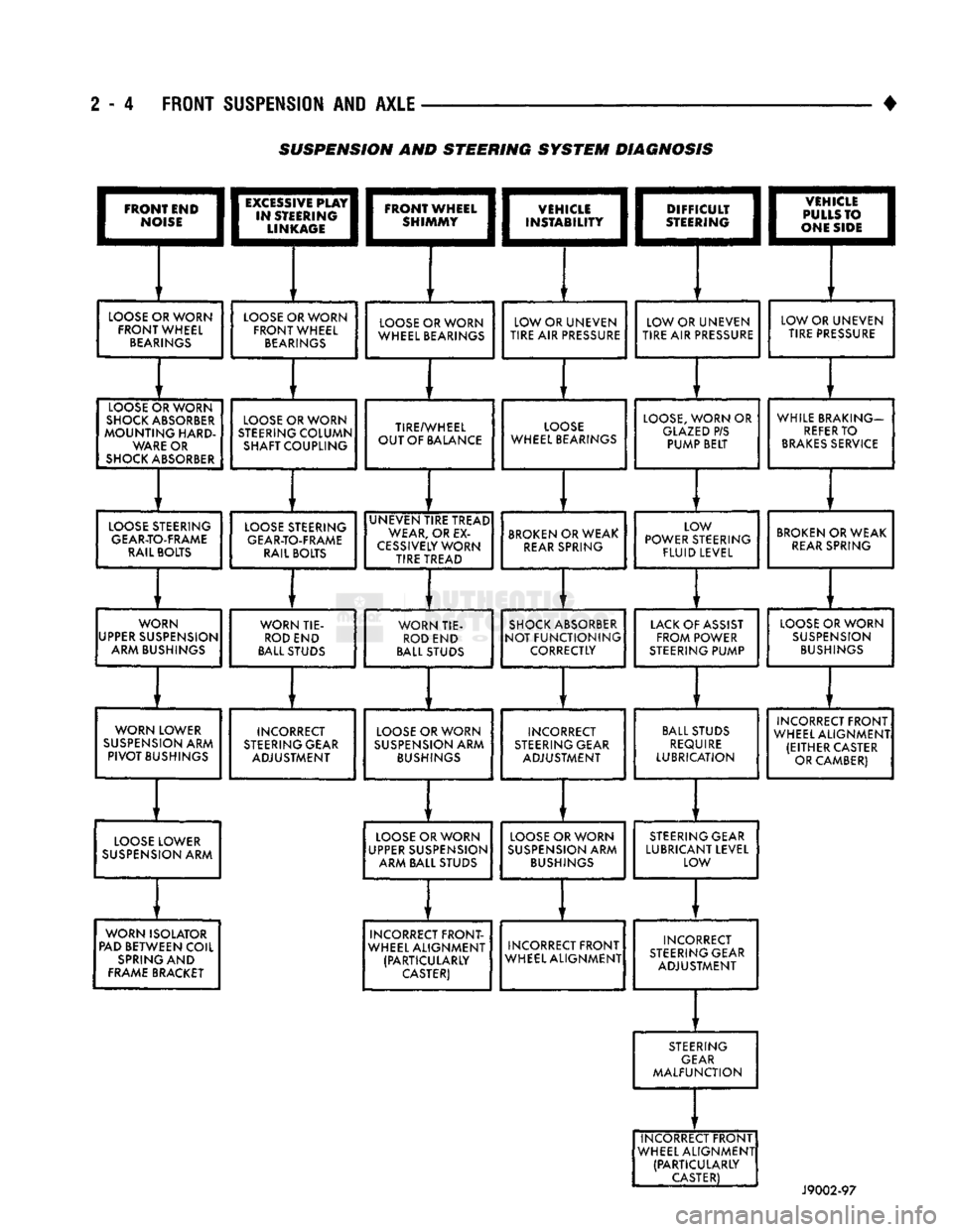
SUSPENSION AND STEERING
SYSTEM
DIAGNOSIS