service DODGE TRUCK 1993 Service User Guide
[x] Cancel search | Manufacturer: DODGE, Model Year: 1993, Model line: TRUCK, Model: DODGE TRUCK 1993Pages: 1502, PDF Size: 80.97 MB
Page 25 of 1502
0 - 6
LUBRICATION
AND
MAINTENANCE
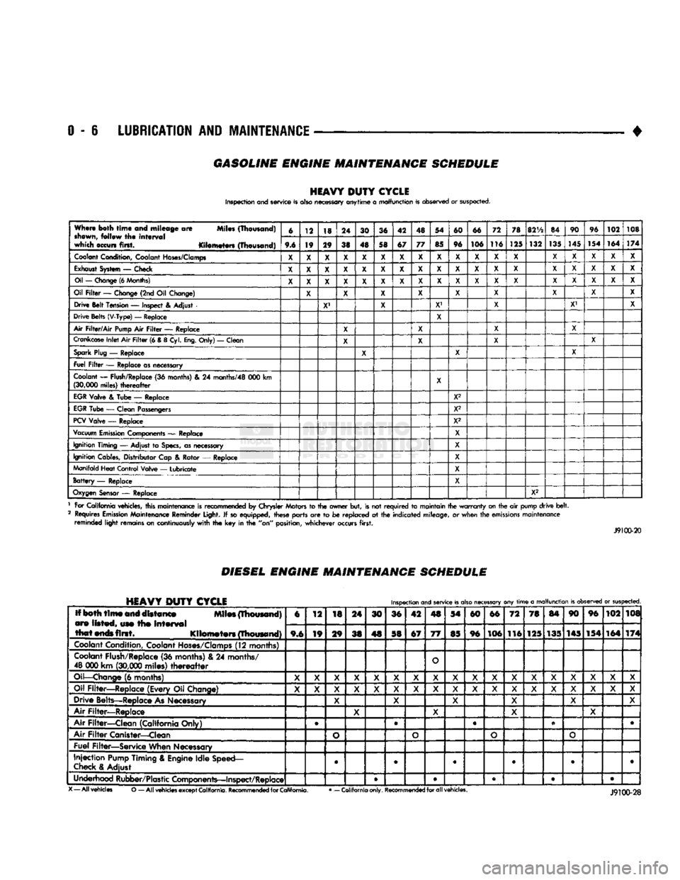
GASOLINE ENGINE MAINTENANCE SCHEDULE
HEAVY
DUTY
CYCLE
Inspection and service is also necessary anytime
a
malfunction is observed or suspected.
When both
time
and mileage
are
Miles (Thousand)
shewn,
follow
the
interval
which occurs first. Kilometers (Thousand) 6
12 18 24
30 36 42 48 54
60 66 72
78
82V2
84 90
96
102 108
When both
time
and mileage
are
Miles (Thousand)
shewn,
follow
the
interval
which occurs first. Kilometers (Thousand) 9.6 19 29
38 48 58 67 77
85 96 106 116
125 132
135
145
154 164
174
Coolant
Condition, Coolant
Hoses/Clamps
X
X X X
X X X X
X X X X
X X X
X X X
Exhaust
System
—
Check
X X X X X X X X X X X
X X X X X
X X
Oil
—
Change
(6
Months)
X X X X X X X
X X
X
X
X
X X X
X X
X
Oil
Filter
—
Change (2nd
Oil
Change)
X X X X
X X
X X
X
Drive Belt Tension
—
Inspect
&
Adjust
X' X
X1
X X' X
Drive Belts (V-Type)
—
Replace
X
Air
Filter/Air
Pump
Air
Filter
—
Replace
X X X
X
Crankcase
Inlet
Air
Filter
(6 &
8
Cyl.
Eng.
Only)
—
Clean
X X
X X
Spark
Plug
—
Replace
X X X
Fuel
Filter
—
Replace as necessary
Coolant
—
Flush/Replace
(36
months)
& 24
months/48
000 km
(30,000
miles)
thereafter
X
EGR
Valve
&
Tube
—
Replace X2
EGR
Tube
—
Clean Passengers
X2
PCV
Valve
—
Replace X2
Vacuum
Emission
Components
—
Replace
X
Ignition Timing
—
Adjust
to
Specs,
as necessary X
Ignition Cables, Distributor Cap
&
Rotor
—
Replace
X
Manifold Heat Control Valve
—
Lubricate
X
Battery
—
Replace X
Oxygen
Sensor
—
Replace
X2
1 For California vehicles, this maintenance is recommended
by
Chrysler Motors
to the
owner but, is not
required
to
maintain the
warranty
on the
air
pump drive
belt.
2 Requires
Emission
Maintenance Reminder Light.
If
so equipped, these parts
are to be
replaced
at the
indicated mileage,
or
when the
emissions
maintenance reminded light remains on continuously
with
the key in the
"on" position, whichever occurs first.
J9100-20
DIESEL
ENGINE
MAINTENANCE
SCHEDULE
HEAVY
DUTY
CYCLE
Inspection
and
service
is
also
necessary
any
time
a
malfunction
is
observed
or
suspected.
Iff both
time
and distance Miles (Thousand)
are listed, use the
interval
that
ends
first. Kilometers (Thousand) 6
12
18 24
30 36 42
4S
54
60 66
72 78
84 90 96
102 108
Iff both
time
and distance Miles (Thousand)
are listed, use the
interval
that
ends
first. Kilometers (Thousand) 9,6 19
29
38 48 58 67
77
85 96 106
116 125 135 145 154
164 174
Coolant
Condition, Coolant
Hoses/Clamps
(12 months)
Coolant
Flush/Replace (36 months) & 24 months/
48 000 km
(30,000
miles)
thereafter
O
Oil—Change
(6 months)
X X X
X X X
X X X X X
X X X X X X
X
Oil Filter—Replace (Every Oil Change)
X X X
X X X
X X
X X X
X
X X X X
X X
Drive Belts—Replace
As
Necessary
X X
X X X X
Air Filter—Replace
X X
X X
Air Filter—Clean (California Only) e
®
• •
Air
Filter
Canister—Clean
o o o
o
Fuel Filter—Service When Necessary
Injection
Pump
Timing & Engine Idle Speed—
Check
& Adjust
©
• 9 • • •
Underhood Rubber/Plastic Components—Inspect/Replace • • • • •
X
— All vehicles
O
— All
vehicles
except
California.
Recommended
for
California.
•
— California only.
Recommended
for all vehicles.
Page 26 of 1502
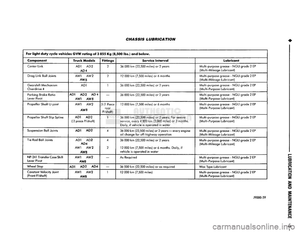
CHASSIS LUBRICATION
For light
duty
cycle
vehicles
GVW resting
of
3 855 Kg (8,500 lbs ) and
below.
Component
Truck Models
Fittings
Service Interval Lubricant
Center Link
AD1
AD2
AD
4
2
36
000
km
(22,500
miles)
or 2
years Multi-purpose grease
-
NGLI
grade
2
EP
(Multi-Mileage Lubricant)
Drag
Link
Bali
joints
AW1 AW 2
AW
8
2
12
000
km
(7,500
miles)
or 6
months Multi-purpose grease
-
NGLI
grade
2
EP
(Multi-Mileage Lubricant)
Gearshift
Mechanism
Overdrive
4
AD1
1
36
000
km
(22,500
miles)
or 2
years Multi-purpose grease
-
NGLI
grade
2
EP
(Multi-Purpose Lubricant)
Parking Brake Ratio
Lever
Pivot
AD1 AD
2 AD 4
AW1 AW 8
—
36
000
km
(22,500
miles)
or 2
years
Multi-purpose grease
-
NGLI
grade
2
EP
(Multi-Purpose Lubricant)
Propeller Shaft
U-joint
AW1
AW2
AW 8
3
(1
Piece
rear
P/shaft)
12
000
km
(7,500
miles)
or 6
months
Multi-purpose grease
-
NGLI
grade
2
EP
(Multi-Purpose Lubricant)
Propeller Shaft
Slip
Spline
AD1 AD
2
(2
piece P/shaft)
1
36
000
km
(22,500
miles)
or 2
years. For severe
service,
every
4
800
km
(3,000
miles)
or 3
months. Daily,
if
vehicle is operated in
water
Multi-purpose grease
-
NGLI
grade
2
EP
(Multi-Purpose Lubricant)
Suspension
Ball Joints
AD1 AD
2
4
36
000
km
(22,500
miles) or 2 years
—
every
engine
oil change
for
off-highway operation Multi-purpose grease
-
NGLI
grade
2
EP
(Multi-Mileage Lubricant)
Tie Rod Ball Joints
AD1
AD2
AD4
AW1 AW
2
AW8 4
2
36
000
km
(22,500
miles)
or 2
years
12
000
km
(7,500
miles)
or 6
months. Daily,
if
vehicle is operated in
water
Multi-purpose grease
-
NGLI
grade
2
EP
(Multi-Mileage Lubricant)
NP-241 Transfer
Case
Shift
Lever Pivot
AW1
AW2
AW8
—
As
Required
Multi-purpose grease
-
NGLI
grade
2
EP
(Multi-Purpose Lubricant)
Wheel
Stop
AD1 AD
2
AD4
—
36
000
km
(22,500
miles)
or
as
required
Wax Type Lubricant
Constant
Velocity Joint
(Front
P/shaft)
AW1
AW2
AW8 1
12
000
km
(7,500
miles) Multi-purpose grease
-
NGLI
grade
2
EP
(Multi-Purpose Lubricant)
>
J9000-59
>
Page 27 of 1502
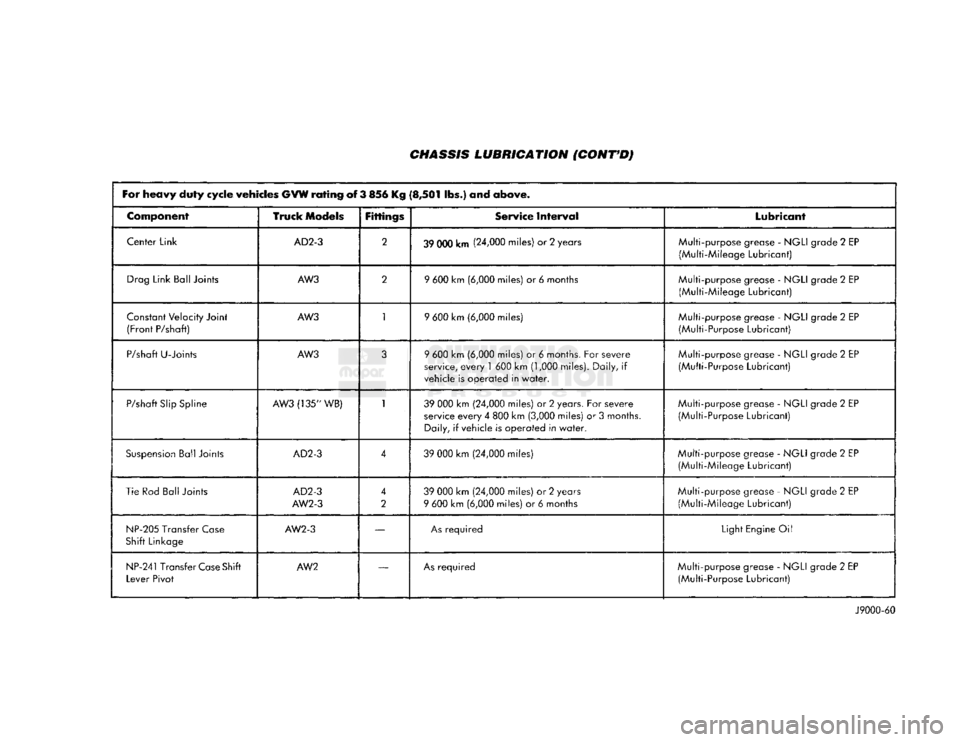
CHASSIS LUBRICATION
(CONT'D)
For
heavy
duty
cycle
vehicles
GVW
rating
of 3 856 Kg
(8,501
Sbs.) and
above.
Component
Truck
Models
Fittings
Service
Interval
Lubricant
Center Link
AD2-3
2
39 000 km (24,000 miles) or 2 years Multi-purpose grease -
NGLI
grade 2 EP
(Multi-Mileage Lubricant)
Drag
Link Ball Joints
AW3
2
9
600 km (6,000 miles) or 6 months
Multi-purpose grease -
NGLI
grade 2 EP
(Multi-Mileage Lubricant)
Constant
Velocity Joint
(Front
P/shaft)
AW3
1
9
600 km (6,000 miles) Multi-purpose grease -
NGLI
grade 2 EP
(Multi-Purpose Lubricant)
P/shaft
U-Joints
AW3
3
9
600 km (6,000 miles) or 6 months. For severe
service,
every
1
600 km (1,000 miles). Daily, if
vehicle is
operated
in
water.
Multi-purpose grease -
NGLI
grade 2 EP
(Multi-Purpose Lubricant)
P/shaft
Slip
Spline
AW3
(135" WB)
1
39
000 km (24,000 miles) or 2 years. For severe
service
every
4 800 km (3,000 miles) or 3 months.
Daily, if vehicle is
operated
in
water.
Multi-purpose
grease -
NGLI
grade 2 EP
(Multi-Purpose Lubricant)
Suspension
Ball Joints
AD2-3
4
39
000 km (24,000 miles) Multi-purpose grease -
NGLI
grade 2 EP
(Multi-Mileage Lubricant)
Tie Rod
Ball
Joints
AD2-3
AW2-3
4
2
39
000 km (24,000
miles)
or 2 years
9
600 km (6,000 miles) or 6 months Multi-purpose grease -
NGLI
grade 2 EP
(Multi-Mileage Lubricant)
NP-205
Transfer
Case
Shift
Linkage
AW2-3
—
As
required
Light
Engine Oil
NP-241
Transfer
Case
Shift
Lever
Pivot
AW2
—
As
required
Multi-purpose grease -
NGLI
grade 2 EP
(Multi-Purpose Lubricant)
J9000-60
Page 30 of 1502
LUBRICATION
AND
MAINTENANCE
0-11
J
DRIVE-ON
HOIST
I
FRAME
CONTACT
HOIST
TWIN
POST
CHASSIS
HOIST
FLOOR
JACK
RROOD30
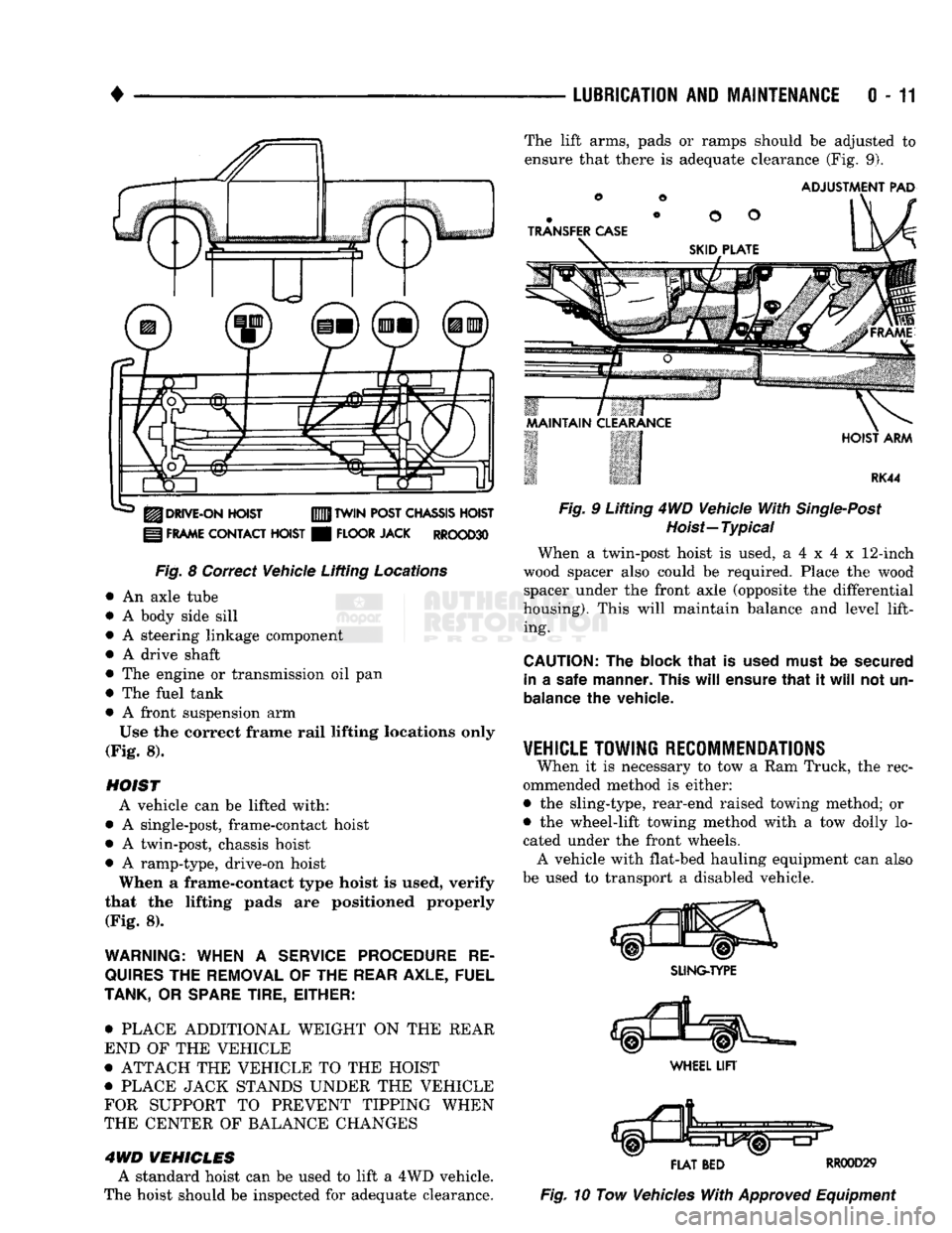
Fig.
8 Correct Vehicle Lifting
Locations
An axle tube
A body side sill
A steering linkage component
A drive shaft
The engine or transmission oil pan
The fuel tank
• A front suspension arm Use the correct frame rail lifting locations only
(Fig. 8).
HOIST A vehicle can be lifted with:
• A single-post, frame-contact hoist
• A twin-post, chassis hoist
• A ramp-type, drive-on hoist
When a frame-contact type hoist is used, verify
that the lifting pads are positioned properly (Fig. 8).
WARNING:
WHEN
A
SERVICE
PROCEDURE
RE
QUIRES
THE
REMOVAL
OF
THE
REAR
AXLE,
FUEL
TANK,
OR
SPARE
TIRE,
EITHER:
• PLACE ADDITIONAL WEIGHT ON THE REAR
END OF THE VEHICLE
« ATTACH THE VEHICLE TO THE HOIST
« PLACE JACK STANDS UNDER THE VEHICLE
FOR SUPPORT TO PREVENT TIPPING WHEN
THE CENTER OF BALANCE CHANGES
4WD VEHICLES A standard hoist can be used to lift a 4WD vehicle.
The hoist should be inspected for adequate clearance. The lift arms, pads or ramps should be adjusted to
ensure that there is adequate clearance (Fig. 9).
ADJUSTMENT
PAD
ii 7
MAINTAIN
CLEARANCE
HOIST
ARM
RK44
Fig.
9 Lifting 4WD Vehicle
With
Single-Post
Hoist—
Typical
When a twin-post hoist is used, a 4 x 4 x 12-inch
wood spacer also could be required. Place the wood spacer under the front axle (opposite the differential
housing). This will maintain balance and level lift ing.
CAUTION:
The
block
that
is
used must
be
secured in
a
safe manner. This
will
ensure
that
it
will
not un
balance
the
vehicle.
VEHICLE
TOWING
RECOMMENDATIONS
When it is necessary to tow a Ram Truck, the rec
ommended method is either:
• the sling-type, rear-end raised towing method; or
• the wheel-lift towing method with a tow dolly lo
cated under the front wheels. A vehicle with flat-bed hauling equipment can also
be used to transport a disabled vehicle.
SLING-TYPE
FLAT
BED
RR0OD29
Fig.
10 Tow Vehicles
With
Approved
Equipment
Page 33 of 1502
0 - 14
LUBRICATION
AND
MAINTENANCE
•
ENGINE
MAINTENANCE
INDEX
page
Air
Injection
Systems/Air Pump
. 17
Air-Conditioner
Compressor
21
Battery
19
Cooling System
15
Crankcase
Ventilation
System
17
Diesel Engine
Air Filter
Canister
17
Drive Belts
20
Engine
Air
Cleaner
Filter
Element
16
Engine Break-In
14
Engine
Oil 14
Engine
Oil
Change
and Filter
Replacement
15
Exhaust Gas
Recirculation
(EGR) System
...... 19
page
Exhaust
Manifold
Heat
Control
Valve
. 17
Exhaust System
, 21
Fuel System
18
Hoses
and
Fittings
16
Ignition
Cables,
Distributor
Cap and
Rotor
...... 19
Ignition
Timing
. 19
Oxygen
(02)
Sensor
19
Rubber/Plastic Components
20
Spark Plugs
. 19
Throttle
Control
Linkage
18
Vacuum Operated, Emission
Control
Components
19
ENGINE BREAK-IN
After first starting a new engine, allow it to idle
for 15 seconds before shifting into a drive gear. Also:
• Drive the vehicle at varying speeds less than 88
km/h (55 mph) for the first 480 km (300 miles).
• Avoid fast acceleration and sudden stops.
• Do not drive at full-throttle for extended periods of
time
• Do not drive at constant speeds
• Do not idle the engine excessively A special break-in engine oil is not required. The
original engine oil installed is a high quality lubri
cant. New engines tend to consume more fuel and oil un
til after the break-in period has ended.
ENGINE
OIL SPECIFICATIONS
API SERWICE
GRADE
Use an engine oil that conforms to API Service
Grade S5 SG/CD or SG/CE. MOPAR®provides engine
oils that conform to all of these service grades.
SULFATED ASH—DIESEL ENGINES
Oils that contain an excessive amount of sulfated
ash can cause deposits to develop on Diesel engine
valves. These deposits can result in valve wear.
SAE
WISC0SITY
An SAE viscosity grade is used to specify the vis
cosity of engine oil. SAE 30 specifies a single viscos
ity engine oil.
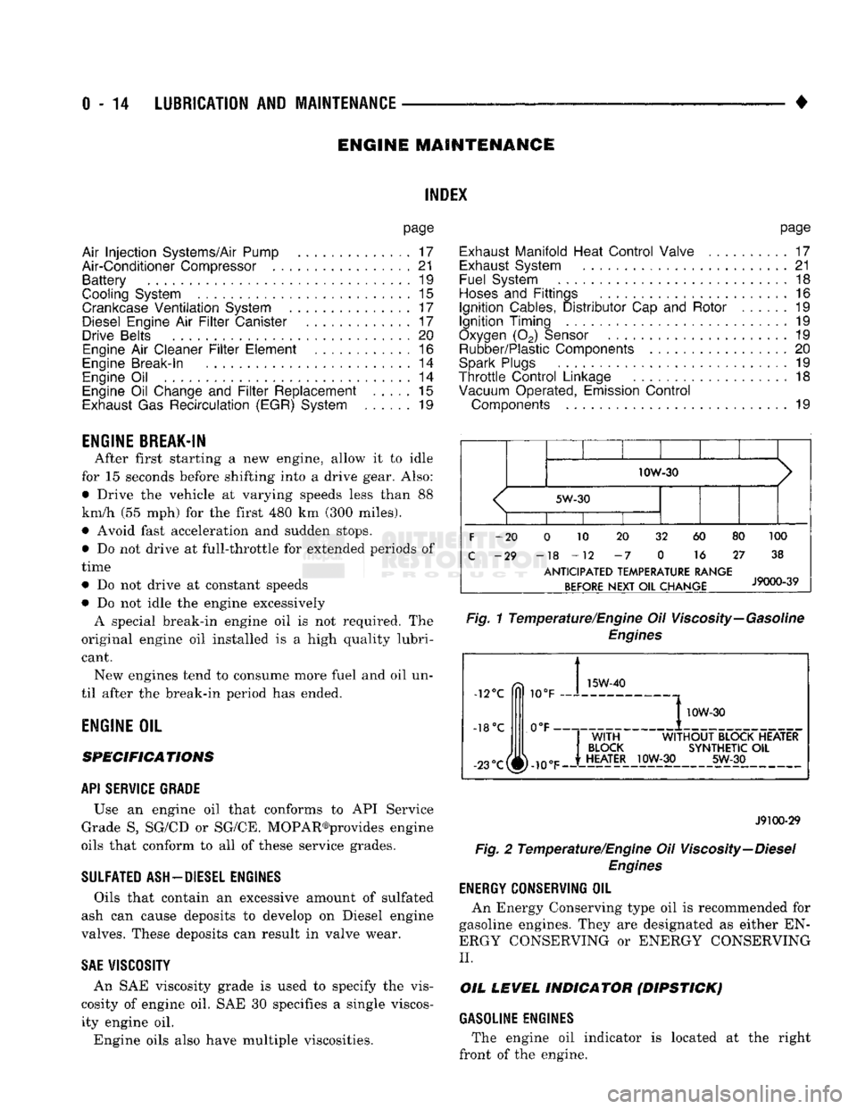
Engine oils also have multiple viscosities. 10W-30
<
5W-30
1
1 1
F
-20 0 10 20 32 60 80 100
C
-29 -18 -12 -7 0 16 27 38
ANTICIPATED
TEMPERATURE RANGE BEFORE
NEXT
OIL
CHANGE
J9000-39
Fig.
1 Temperature/Engine Oil Viscosity—Gasoline
Engines
-12°C
-18°C 10°F
0°F- 15W-40
-23°c(^-10eF
I
10W-30
WITH
WITHOUT
BLOCK HEATER
BLOCK
SYNTHETIC
OIL
HEATER
10W-30 5W-30
J9100-29
Fig.
2 Temperature/Engine Oil Viscosity—Diesel
Engines
ENERGY
G0NSERWING
OIL
An Energy Conserving type oil is recommended for
gasoline engines. They are designated as either EN
ERGY CONSERVING or ENERGY CONSERVING
II.
OIL
LEVEL
INDICATOR (DIPSTICK)
GASOLINE ENGINES
The engine oil indicator is located at the right
front of the engine.
Page 34 of 1502
•
LUBRICATION
AND
MAINTENANCE
0 - 15
DIESEL
ENGINES
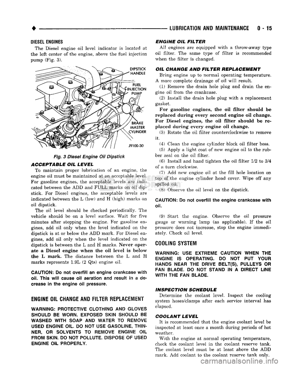
The Diesel engine oil level indicator is located at
the left center of the engine, above the
fuel
injection
pump (Fig. 3).
Fig.
3
Diesel
Engine
Oil
Dipstick
ACCEPTABLE
OIL
LEVEL
To maintain proper lubrication of an engine, the
engine oil must be maintained at an acceptable level.
For gasoline engines, the acceptable levels are indi cated between the ADD and
FULL
marks on oil
dip
stick. For Diesel engines, the acceptable levels are
indicated between the L (low) and H
(high) marks
on
oil dipstick. The oil level should be checked periodically. The
vehicle should be on a level surface. Wait for
five
minutes after stopping the engine. For gasoline en
gines,
add oil only when the level indicated on the
dipstick is at or below the ADD mark. For Diesel en
gines,
add oil only when the level indicated on the
dipstick is between the L and H marks.
Never oper
ate a Diesel
engine when
the oil
level
is below
the L mark. The distance between the L and H
marks represents 1.9L (2 Qts) engine oil.
CAUTION:
Do not
overfill
an
engine crankcase
with
oil. This
will
cause
oil
aeration
and
result
in a de
crease
in the
engine
oil
pressure.
ENGINE
OIL
CHANGE AND FILTER REPLACEMENT
WARNING: PROTECTIVE CLOTHING
AND
GLOVES SHOULD
BE
WORN. EXPOSED SKIN SHOULD
BE
WASHED
WITH
SOAP
AND
WATER
TO
REMOVE
USED
ENGINE
OIL.
DO NOT
USE
GASOLINE, THIN
NER,
OR
SOLVENTS
TO
REMOVE ENGINE
OIL
FROM
SKIN.
DO NOT
POLLUTE. DISPOSE
OF
USED
ENGINE
OIL
PROPERLY.
ENGINE
OIL
FILTER
All engines are equipped with a throw-away type
oil filter. The same type of filter is recommended
when the filter is changed.
OIL CHANGE
AND
FILTER
REPLACEMENT
Bring engine up to normal operating temperature.
A more complete drainage of oil will result.
(1) Remove the drain hole plug and drain the en
gine oil from the crankcase.
(2) Install the drain hole plug with a replacement
gasket. For gasoline engines, the oil filter should be
replaced during every second engine oil change.
For Diesel engines, the oil filter should be re
placed during every engine oil change.
(3) Rotate the oil filter counterclockwise to remove
it.
(4) Clean the engine cylinder block oil filter boss. (5) Apply a light coat of new engine oil to the rub
ber seal on the oil filter.
(6) Install and hand tighten the oil filter 1/2 to 3/4
of a turn clockwise. (7) Add new engine oil at the fill hole location on
top of the engine cylinder head cover. Wipe off any spilled oil.
(8) Observe the oil level on the dipstick.
CAUTION:
Do not
overfill
the
engine crankcase
with
oil.
(9)
Start the engine. Observe the oil pressure
gauge or warning lamp (as applicable). If the oil
pressure does not increase, stop the engine immedi ately. Check oil level.
COOLING SYSTEM
WARNING:
USE
EXTREME CAUTION WHEN
THE
ENGINE
IS
OPERATING.
DO NOT PUT
YOUR
HANDS NEAR
THE
DRIVE BELT(S), PULLEYS
OR
FAN BLADE.
DO NOT
STAND
IN A
DIRECT LINE
WITH
THE FAN
BLADE.
INSPECTION SCHEDULE
Determine the coolant level. Inspect the cooling
system hoses/clamps after each service interval has
elapsed.
COOLANT LEVEL
It is recommended that the engine coolant level be
inspected at least once a month during periods of hot
weather.
With the engine at normal operating temperature,
check the coolant level in the coolant reserve tank.
The coolant level must be at least above the ADD mark. Add coolant to the coolant reserve tank only.
Page 35 of 1502
0-18
LUBRICATION
AND
MAINTENANCE
•
COOLANT FREEZE PROTECTION
Cooling systems contain a 50/50 mixture of anti
freeze (ethylene glycol) and distilled water. This is
the recommended coolant mixture.
It is recommended that the degree of coolant pro
tection be tested every 12 months. If the coolant is
contaminated or rusty, the cooling system should be
drained, flushed. Refill with a 50/50 mixture of fresh
coolant. Refer to Group 7—Cooling Systems for addi
tional information.
SYSTEM
INSPECTION
WARNING:
IF THE
ENGINE
HAS
BEEN RECENTLY
OPERATED,
DO NOT
REMOVE
THE
RADIATOR
CAP.
THIS WILL AVOID
YOU
BEING SCALDED
WITH
HOT, PRESSURIZED COOLANT.
(1) Test the radiator cap for proper sealing and op
eration. Use caution when removing the radiator cap
to avoid contact with hot coolant. Place a heavy rag
or towel over the cap and turn to the first stop. Do
not press down. Pause to allow the pressure to re
lease through the overflow tube. Then press down
and turn counterclockwise to remove the cap.
(2) Inspect the coolant overflow tubing and the
connections at the coolant reserve tank and at the
radiator.
(3) Inspect the entire cooling system for leaks. A
black-light detector can be used as an aid in detect ing the source of coolant leaks.
(4) Inspect the radiator and air conditioner con
denser fins for debris, etc. (5) If necessary, refer to Group 7—Cooling Systems
for additional information and service procedures.
RADIATOR CAP
The radiator cap must be completely tightened to
provide proper pressure. Inspect and test radiator cap
when cooling system service is performed.
MAIN,
FLUSH
AND
FILL
WARNING: ANTI-FREEZE (ETHYLENE GLYCOL)
IS
POISONOUS.
KEEP
OUT OF THE
REACH
OF
CHIL
DREN.
Drain, flush, and fill the cooling system at the in
terval specified in maintenance schedule. For proper service instructions see Group 7, Cooling System.
HOSES AND
FITTINGS
It is recommended that rubber hoses be periodi
cally inspected. Inspect all hose fittings for looseness and corrosion.
ENGINE
AIR
CLEANER
FILTER
ELEMENT
MAINTENANCE
SCHEDULE
With normal driving conditions, the engine air
cleaner filter element should be replaced:
• Light-Duty Cycle-after each 48 000 km (30,000
miles) interval has elapsed
• Heavy-Duty Cycle-after
each
38 000 km (24,000
miles) interval has elapsed
When the vehicle is operated in dusty areas, the
filter element should be replaced more often.
For Diesel engines, the air filter canister should be
cleaned at the same time the filter is replaced.
SERVICE/REPLACEMENT
(1) Remove the air cleaner cover.
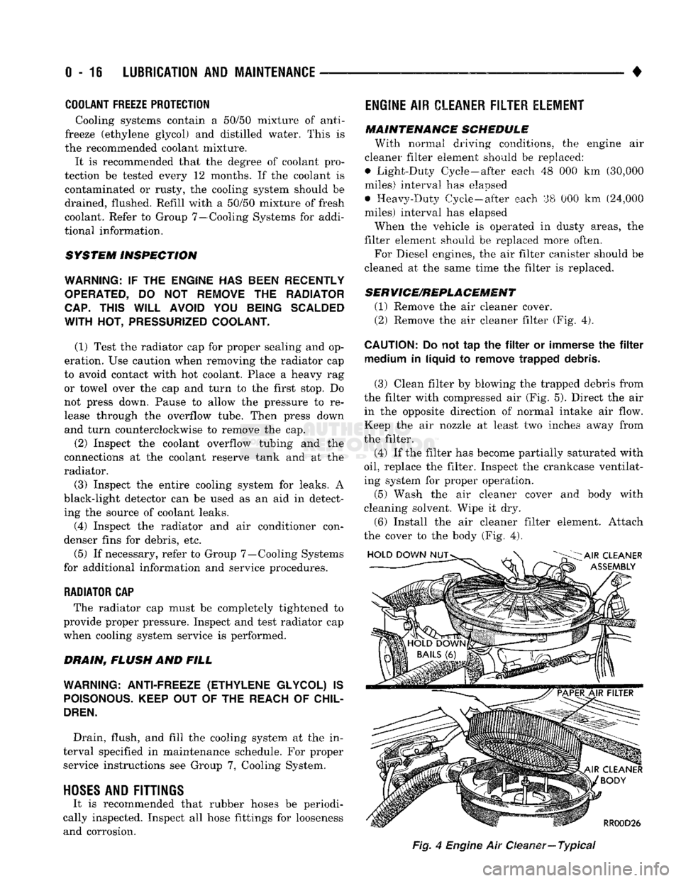
(2) Remove the air cleaner filter (Fig. 4).
CAUTION:
Do not tap the filter or immerse the filter medium in liquid to remove trapped debris.
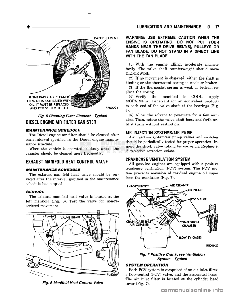
(3) Clean filter by blowing the trapped debris from
the filter with compressed air (Fig. 5). Direct the air in the opposite direction of normal intake air flow.
Keep the air nozzle at least two inches away from
the filter.
(4) If the filter has become partially saturated with
oil,
replace the filter. Inspect the crankcase ventilat
ing system for proper operation.
(5) Wash the air cleaner cover and body with
cleaning solvent. Wipe it dry.
(6) Install the air cleaner filter element. Attach
the cover to the body (Fig. 4).
Fig,
4
Engine
Air Oeaner—
Typical
Page 36 of 1502
•
Fig.
5
Cleaning
Filter
Element—Typical
DIESEL
ENGINE
AIR
FILTER CANISTER MAINTENANCE SCHEDULE
The Diesel engine air filter should be cleaned after
each interval specified in the Diesel engine mainte
nance schedule.
When the vehicle is operated in dusty areas, the
canister should be cleaned more frequently.
EXHAUST
MANIFOLD HEAT CONTROL VALVE
MAINTENANCE SCHEDULE
The exhaust manifold heat valve should be ser
viced after the interval specified in the maintenance schedule has elapsed.
SERVICE The exhaust manifold heat valve is located at the
left manifold (Fig. 6). Test the valve for non-re stricted movement.
Fig.
6 Manifold Heat Control
Valve
LUBRICATION
AND
MAINTENANCE
0 - 17
Fig.
7 Positive
Crankcase
Ventilation
System—Typical
SYSTEM OPERATION
Each PCV system is comprised of an air inlet filter,
a flow-control (PCV) valve, and the associated hoses.
The air inlet filter is located at the cylinder head cover (Fig. 7).
WARNING:
USE
EXTREME CAUTION WHEN
THE
ENGINE
IS
OPERATING.
DO NOT PUT
YOUR
HANDS NEAR
THE
DRIVE BELT(S), PULLEYS
OR
FAN BLADE.
DO NOT
STAND
IN A
DIRECT LINE
WITH
THE FAN
BLADE.
(1) With the engine idling, accelerate momen
tarily. The valve shaft counterweight should move CLOCKWISE.
(2) If no movement is observed, either the shaft is
binding or the thermostat spring is weak or broken. (3) If the thermostat spring is weak or broken, re
place the spring.
(4) Verify the manifold is COOL. Apply
MOPAR®Rust Penetrant (or an equivalent product)
to each end of the valve shaft at the bearings (Fig.
6).
(5) Allow the solvent to penetrate for a few min
utes.
Then, rotate the valve shaft back and forth un
til it turns without restriction.
AIR INJECTION SYSTEMS/AIR PUMP
Air injection system/air pump valves and switches
should be periodically tested for proper operation. In
spect the check valve tubing for corrosion. Replace it
if excessive corrosion exists.
CRANKCASE
VENTILATION
SYSTEM
All gasoline engines are equipped with a positive
crankcase ventilation (PCV) system. The PCV sys
tem prevents emission of residual engine oil vapor
from the crankcase (Fig. 7).
Page 37 of 1502
0-18
LUBRICATION
AND
MAINTENANCE
• MAINTENANCE SCHEDULE
A crankcase ventilation system must be clean to
provide good operation and durability. Periodic main
tenance is necessary. Replace the PCV valve. Re
move residual combustion deposits from the hoses and throttle body/intake manifold passages.
The PCV valve should be replaced and the system
should be serviced at the interval specified in main
tenance schedule. If a vehicle is routinely used for short trips, the crankcase ventilation system could
possibly require more maintenance.
CRANKCASE AIR INLET FILTER
MAINTENANCE SCHEDULE Replace or clean, the air inlet filter at the interval
specified in maintenance schedule.
More frequent PCV system maintenance could be
required for:
• Vehicles routinely used for short trips
• Vehicles routinely involved in stop and go traffic
operation
• Vehicles routinely involved in extended periods of
engine idle
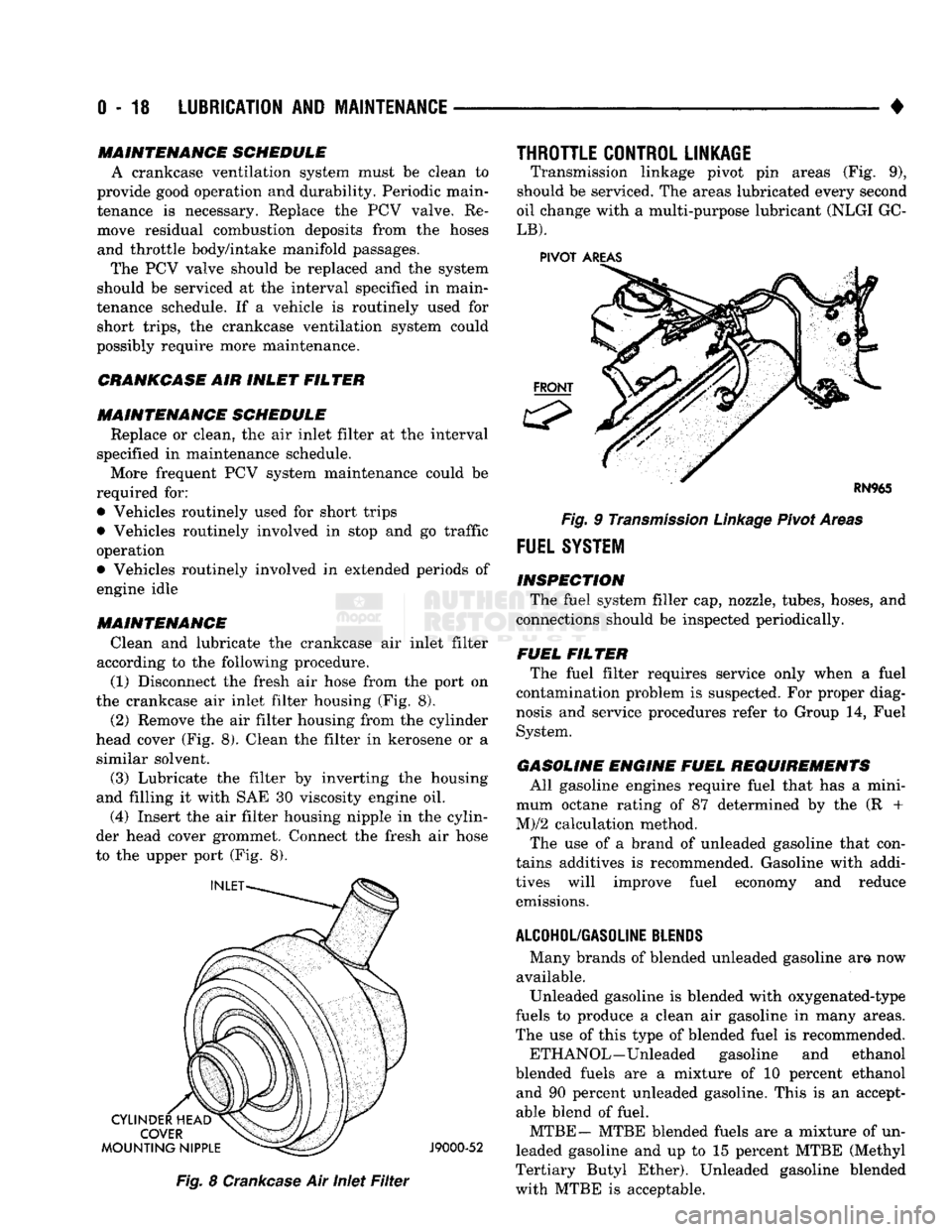
MAINTENANCE Clean and lubricate the crankcase air inlet filter
according to the following procedure. (1) Disconnect the fresh air hose from the port on
the crankcase air inlet filter housing (Fig. 8).
(2) Remove the air filter housing from the cylinder
head cover (Fig. 8). Clean the filter in kerosene or a similar solvent.
(3) Lubricate the filter by inverting the housing
and filling it with SAE 30 viscosity engine oil.
(4) Insert the air filter housing nipple in the cylin
der head cover grommet. Connect the fresh air hose
to the upper port (Fig. 8).
J9000-52
Fig.
8
Crankcase
Air Inlet
Filter
THROTTLE CONTROL LINKAGE
Transmission linkage pivot pin areas (Fig. 9),
should be serviced. The areas lubricated every second
oil change with a multi-purpose lubricant (NLGI GC-
LB).
PIVOT
AREAS
Fig.
9
Transmission
Linkage
Pivot Areas
FUEL
SYSTEM
INSPECTION The fuel system filler cap, nozzle, tubes, hoses, and
connections should be inspected periodically.
FUEL FILTER The fuel filter requires service only when a fuel
contamination problem is suspected. For proper diag
nosis and service procedures refer to Group 14, Fuel
System.
GASOLINE ENGINE FUEL REQUIREMENTS All gasoline engines require fuel that has a mini
mum octane rating of 87 determined by the (R +
M)/2 calculation method.
The use of a brand of unleaded gasoline that con
tains additives is recommended. Gasoline with addi
tives will improve fuel economy and reduce emissions.
ALCOHOL/GASOLINE
BLENDS
Many brands of blended unleaded gasoline am now
available. Unleaded gasoline is blended with oxygenated-type
fuels to produce a clean air gasoline in many areas.
The use of this type of blended fuel is recommended.
ETH ANOL—Unleaded gasoline and ethanol
blended fuels are a mixture of 10 percent ethanol and 90 percent unleaded gasoline. This is an accept
able blend of fuel.
MTBE— MTBE blended fuels are a mixture of un
leaded gasoline and up to 15 percent MTBE (Methyl
Tertiary Butyl Ether). Unleaded gasoline blended
with MTBE is acceptable.
Page 38 of 1502
•
LUBRICATION
AND
MAINTENANCE
0 - 19 ETBE— This fuel is a mixture of unleaded gasoline
and up to 17 percent ETBE (Ethyl Tertiary Butyl
Ether).
Unleaded gasoline blended with ETBE is ac ceptable.
METHANOL—Do not use unleaded gasoline
blended with methanol. The use of this type of alco hol can result in engine performance and damage to
critical components. Engine problems that result
from the use of methanol possibly will not be covered by the new vehicle warranty.
Certain brands of unleaded gasoline contain a per
centage of unidentified alcohol. These types of un
leaded gasoline are not recommended.
ADDITIVES MIXED
WITH
GASOLINE
Use of fuel system cleaning additives should be
avoided. Many of these solutions could contain highly
active solvents. This type of solvent can be harmful
to the gasket and diaphragm material within the fuel system.
DIESEL
ENGINE FUEL REQUIREMENTS
All Diesel engines normally can use number 2D
Diesel fuel for most year-round operations. A fuel
conforming to ASTM Specification D-975 is recom
mended. For extreme cold-weather operation (below
-18°C/0°F), or for prolonged cold-climate operation ei
ther:
• Use No. ID fuel, or
• Add an equal quantity of kerosene to No. 2D fuel (a 50/50 mixture).
Both methods provide protection against fuel gel
ling and waxing.
Diesel fuel seldom is without water contamination.
To help prevent fuel system malfunctions, drain all accumulated water from the separators periodically.
VACUUM OPERATED,
EMISSION
CONTROL
COMPONENTS
MAINTENANCE SCHEDULE
The following emission controls should be replaced
at the interval specified in the maintenance sched
ule:
• Bi-level purge check valves
• Delay valves
• Heated air temperature sensor (HATS)
• Air cleaner vacuum motors
EXHAUST
GAS RECIRCULATION (EGR)
SYSTEM
MAINTENANCE SCHEDULE
Replace the EGR valve and tube, and clean the
passages at the interval specified in maintenance schedule. If necessary, refer to Group 25—Emission
Control Systems for additional information.
OXYGEN
(02)
SENSOR
MAINTENANCE SCHEDULE
Replace the 02 sensor at the interval specified in
maintenance schedule.
IGNITION
CABLES,
DISTRIBUTOR CAP AND
ROTOR
MAINTENANCE SCHEDULE
Replace the ignition cables, distributor cap, and ro
tor at the interval specified in maintenance schedule.
Inspect the distributor for excessive wear and re
place, as necessary. Refer to Group 8D—Ignition Sys
tems for additional information.
IGNITION TIMING
MAINTENANCE SCHEDULE
Test and adjust, if necessary, the ignition timing at
the interval specified in maintenance schedule. Refer
to the specifications listed on the engine Emission Control Information label. Refer to Group 8D—Igni
tion Systems and to Group 25—Emission Control Systems for additional service information.
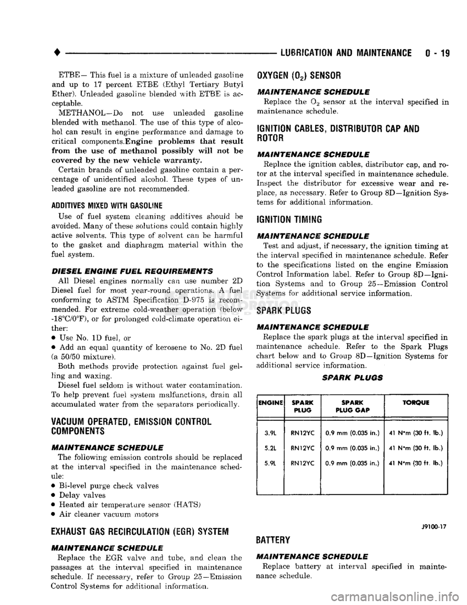
SPARK
PLUGS MAINTENANCE SCHEDULE
Replace the spark plugs at the interval specified in
maintenance schedule. Refer to the Spark Plugs
chart below and to Group 8D—Ignition Systems for additional service information.
SPARK
PLUGS
ENGINE
SPARK
PLUG
SPARK
PLUG
GAP
TORQUE
3.9L
5.2L
5.9L
RN12YC
RN12YC
RN12YC
0.9 mm
(0.035
in.)
0.9 mm
(0.035
in.)
0.9 mm
(0.035
in.) 41 N*m (30 ft. lb.)
41 NVn (30 ft. lb.)
41 N*m (30 ft. lb.)
J9100-17
BATTERY
MAINTENANCE SCHEDULE
Replace battery at interval specified in mainte
nance schedule.