service DODGE TRUCK 1993 Service Owner's Guide
[x] Cancel search | Manufacturer: DODGE, Model Year: 1993, Model line: TRUCK, Model: DODGE TRUCK 1993Pages: 1502, PDF Size: 80.97 MB
Page 60 of 1502
•
FRONT
SUSPENSION
AND
AXLE
2 • 7
FRONT SUSPENSION
—2WD
VEHICLES
INDEX
page
Coil Springs
9
Lower Ball Stud
. 10
Lower Suspension
Arm 10
Lower Suspension
Arm
Bushing
11
Lower Suspension
Arm
Strut
8
Service
Information
7
Shock
Absorber
9
page
Stabilizer
Bar 8
Steering Knuckle
13
Upper Ball Stud
11
Upper Suspension
Arm 11
Upper Suspension
Arm
Bushing Replacement
. . . 12
Wheel
Hub and
Bearings
7
SERVICE
INFORMATION
Periodic lubrication of the front suspension (steer
ing) system components is required. Refer to Group 0, Lubrication And Maintenance for the service in
terval.
Rubber bushings must never be lubricated.
All front suspension components that are
cushioned by rubber should be tightened with
the suspension system at the normal height.
WHEEL
HUB
AND
BEARINGS
REMOVAL (1) Block the brake pedal in the up (non-depressed)
position.
(2) Raise and support the vehicle.
(3) Remove the wheel.
(4) Remove bolts from the disc brake caliper.
(5) Separate the disc brake caliper from the rotor.
Position and support the caliper away from the im
mediate work area. Do not allow the caliper to
hang from the brake fluid hose.
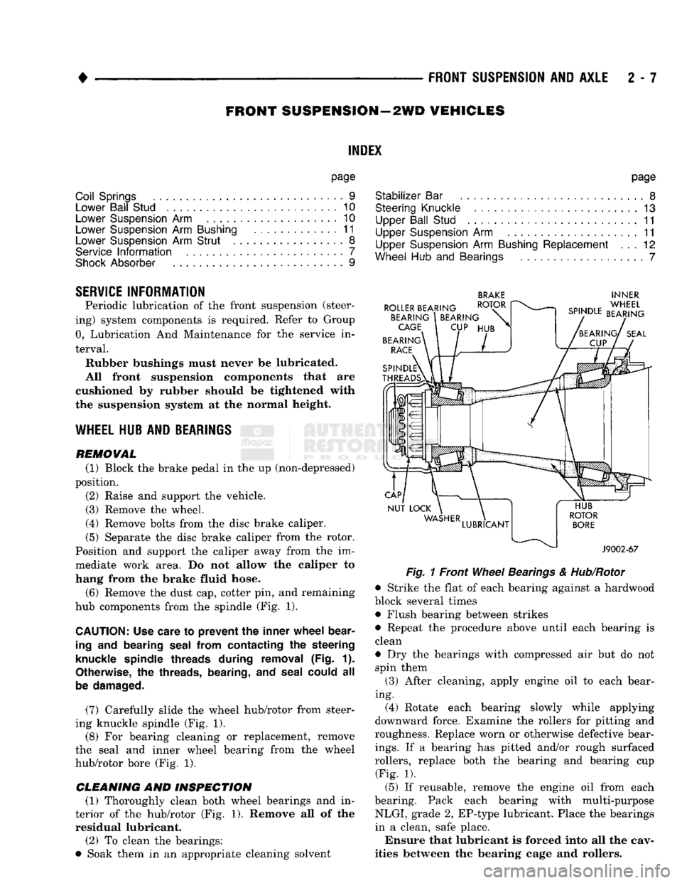
(6) Remove the dust cap, cotter pin, and remaining
hub components from the spindle (Fig. 1).
CAUTION:
Use care
to
prevent
the
inner wheel bear
ing
and
bearing seal from contacting
the
steering
knuckle spindle threads during removal
(Fig. 1).
Otherwise,
the
threads, bearing,
and
seal could
all
be damaged.
(7) Carefully slide the wheel hub/rotor from steer
ing knuckle spindle (Fig. 1).
(8) For bearing cleaning or replacement, remove
the seal and inner wheel bearing from the wheel
hub/rotor bore (Fig. 1).
CLEANING AND INSPECTION (1) Thoroughly clean both wheel bearings and in
terior of the hub/rotor (Fig. 1). Remove all of the residual lubricant.
(2) To clean the bearings:
• Soak them in an appropriate cleaning solvent
BRAKE
INNER
Fig.
1 Front
Wheel
Bearings
&
Hub/Rotor
• Strike the flat of each bearing against a hardwood
block several times • Flush bearing between strikes
• Repeat the procedure above until each bearing is
clean
• Dry the bearings with compressed air but do not spin them
(3) After cleaning, apply engine oil to each bear
ing. (4) Rotate each bearing slowly while applying
downward force. Examine the rollers for pitting and
roughness. Replace worn or otherwise defective bear
ings.
If a bearing has pitted and/or rough surfaced
rollers, replace both the bearing and bearing cup (Fig. 1).
(5) If reusable, remove the engine oil from each
bearing. Pack each bearing with multi-purpose NLGI, grade 2, EP-type lubricant. Place the bearings
in a clean, safe place.
Ensure that lubricant is forced into all the cav
ities between the bearing cage and rollers.
Page 66 of 1502
•
Fig.
11 Upper Suspension Arm Bushing installation
STEERING KNUCKLE
REMOVAL
(1) Block the brake pedal in the up position. Raise
the vehicle and remove the wheel cover and wheel/
tire.
Remove the brake caliper, refer to Group 5,
Brakes. (2) Remove the brake rotor from the spindle. Refer
to Wheel Hub and Bearings service procedures
within this Group.
(3) Remove the brake splash shield. Remove and
discard the dust seal.
(4) Remove the cotter pin and the nut from the tie-
rod end ball stud.
(5)
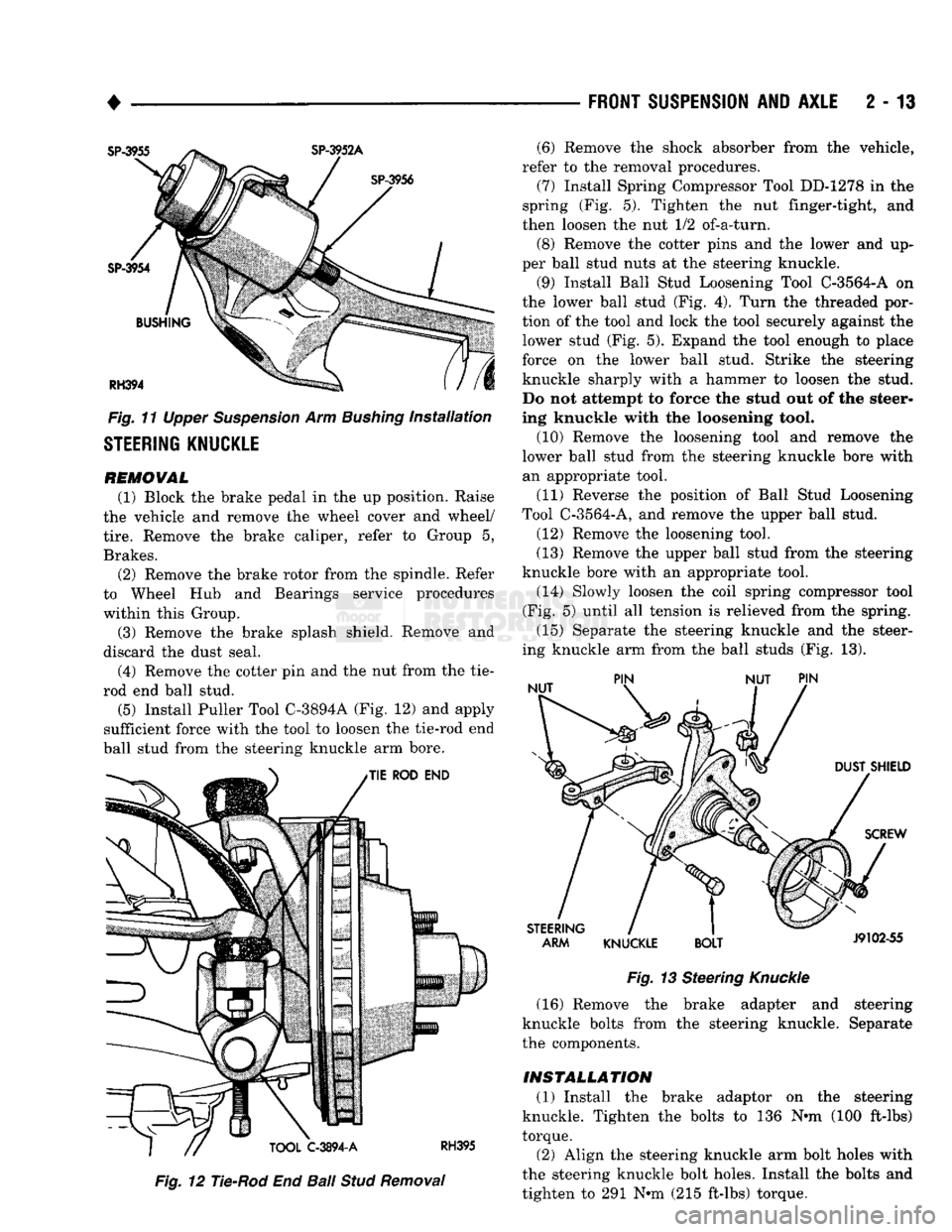
Install Puller Tool C-3894A (Fig. 12) and apply
sufficient force with the tool to loosen the tie-rod end
ball stud from the steering knuckle arm bore.
Fig.
12 Tie-Rod End
Ball
Stud
Removal
FRONT SUSPENSION
AND
AXLE
2 - 13
Fig.
13 Steering
Knuckle
(16) Remove the brake adapter and steering
knuckle bolts from the steering knuckle. Separate
the components.
INSTALLATION (1) Install the brake adaptor on the steering
knuckle. Tighten the bolts to 136 Nnn (100 ft-lbs)
torque.
(2) Align the steering knuckle arm bolt holes with
the steering knuckle bolt holes. Install the bolts and
tighten to 291 Nnn (215 ft-lbs) torque. (6) Remove the shock absorber from the vehicle,
refer to the removal procedures. (7) Install Spring Compressor Tool DD-1278 in the
spring (Fig. 5). Tighten the nut finger-tight, and
then loosen the nut 1/2 of-a-turn.
(8) Remove the cotter pins and the lower and up
per ball stud nuts at the steering knuckle.
(9) Install Ball Stud Loosening Tool C-3564-A on
the lower ball stud (Fig. 4). Turn the threaded por
tion of the tool and lock the tool securely against the lower stud (Fig. 5). Expand the tool enough to place
force on the lower ball stud. Strike the steering
knuckle sharply with a hammer to loosen the stud.
Do not attempt to force the stud out of the steer
ing knuckle with the loosening tool.
(10) Remove the loosening tool and remove the
lower ball stud from the steering knuckle bore with an appropriate tool.
(11) Reverse the position of Ball Stud Loosening
Tool C-3564-A, and remove the upper ball stud.
(12) Remove the loosening tool.
(13) Remove the upper ball stud from the steering
knuckle bore with an appropriate tool. (14) Slowly loosen the coil spring compressor tool
(Fig. 5) until all tension is relieved from the spring.
(15) Separate the steering knuckle and the steer
ing knuckle arm from the ball studs (Fig. 13).
Page 67 of 1502
2
- 14
FRONT SUSPENSION
AND
AXLE
• (3) Mount the knuckle to the suspension arms and
install the nuts. Tighten the upper nut to 142 Nnn (105 ft-lbs) torque and the lower nut.
• 11/16-16 bolt, to 183 Nnn (135 ft-lbs) torque
• 3/4-16 bolt, to 237 Nnn (175 ft-lbs) torque Install replacement cotter pins. (4) Connect the tie-rod end. Install and tighten the
nut to 61 Nnn (45 ft-lbs) torque. Install a replace
ment cotter pin. (5) Position a replacement dust seal on the steer
ing knuckle. Install the splash shield and tighten the
bolts to 24 Nnn (18 ft. lbs.) torque. (6) Install the shock absorber, refer to the installa
tion procedures.
(7) Install the hub/rotor, refer to the procedures
above.
(8) Install the brake caliper, refer to Group 5,
Brakes for additional installation information.
(9)
Install the wheel and tire, refer to Wheel and
Tire Installation in this section. Lower the vehicle.
(10) Test the vehicle brakes and the front suspen
sion for proper operation.
FRONT
SUSPENSION—4WD VEHICLES
STABILIZER
BAR REMOVAL
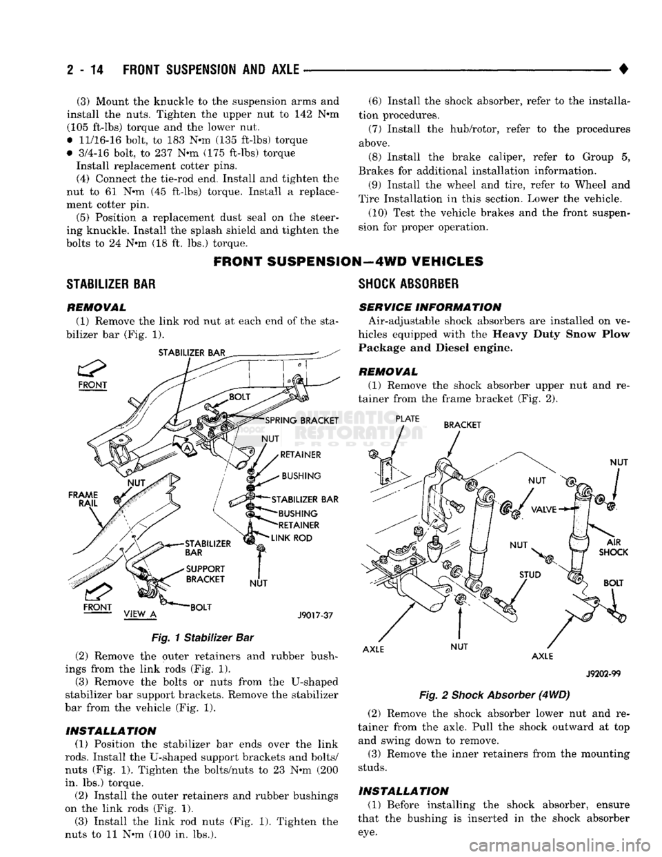
(1) Remove the link rod nut at each end of the sta
bilizer bar (Fig. 1).
STABILIZER BAR
FRONT
STABILIZER BAR BUSHING
RETAINER
LINK
ROD
J9017-37
Fig.
1
Stabilizer
Bar (2) Remove the outer retainers and rubber bush
ings from the link rods (Fig. 1). (3) Remove the bolts or nuts from the U-shaped
stabilizer bar support brackets. Remove the stabilizer
bar from the vehicle (Fig. 1).
INSTALLATION (1) Position the stabilizer bar ends over the link
rods.
Install the U-shaped support brackets and bolts/
nuts (Fig. 1). Tighten the bolts/nuts to 23 Nnn (200
in. lbs.) torque.
(2) Install the outer retainers and rubber bushings
on the link rods (Fig. 1). (3) Install the link rod nuts (Fig. 1). Tighten the
nuts to 11 Nnn (100 in. lbs.).
SHOCK
ABSORBER
SERVICE INFORM
A TION Air-adjustable shock absorbers are installed on ve
hicles equipped with the Heavy Duty Snow Plow Package and Diesel engine.
REMOVAL
(1) Remove the shock absorber upper nut and re
tainer from the frame bracket (Fig. 2).
PLATE
BRACKET
NUT
AXLE NUT
AXLE
J9202-99
Fig.
2
Shock
Absorber
(4
WD)
(2) Remove the shock absorber lower nut and re
tainer from the axle. Pull the shock outward at top and swing down to remove.
(3) Remove the inner retainers from the mounting
studs.
INSTALLATION (1) Before installing the shock absorber, ensure
that the bushing is inserted in the shock absorber
eye.
Page 70 of 1502
•
FRONT
SUSPENSION
AND
AXLE
2 - 17
MODEL
44
FRONT
AXLE
INDEX
page
Axle Shaft
and
U-Joint
Service
23
Complete Axle Removal/Installation
31
Differential
Assembly
35
Differential
Disassembly
. 32
Drain
and Refill
19
General
Information
17
Hub,
Spindle
and
Axle Shaft
20
Intermediate
Axle Shaft
30
Lubricant
17
GENERAL
INFORMATION
Model
44
front axles
(Fig. 1)
consists
of an
iron
center casting with axle shaft tubes extending from
either side. The integral type housing, hypoid gear design
has
the centerline
of the
pinion
set
below
the
centerline of
the
ring gear. The axle shaft disconnect housing
is
welded
to the
left axle shaft tube.
A
splined, two-piece axle shaft
is
located
on the
left side
and it is
engaged
or
disen
gaged
by a
shift collar.
The
collar
is
moved
by a
shift
fork controlled
by a
vacuum shift motor.
The
shift motor
is
operated
by
engine vacuum controlled
by a
switch located
at the
transfer case. The axles
are
equipped with full-floating axle
shafts,
meaning that loads
are
supported
by the
spin
dles attached
to the
steering knuckles. The removable, stamped steel cover provides
a
means
for
inspection
and
service without removing
the complete axle from
the
vehicle.
page
Pinion Gear Depth Measurement
and
Adjustment
with
Tool
Set
C-3715-B
40
Pinion Gear Depth Measurement
and
Adjustment
with
Tool
Set
D-115-44
... 38
Pinion Shaft Seal
19
Specifications
48
Steering Knuckle
Arm
31
Steering Knuckle, Upper
and
Lower Ball Studs
. . 24
Vacuum
Shift Motor
26
A small, stamped metal axle gear ratio identifica
tion
tag is
attached
to the
housing cover
via one of
the cover bolts. This
tag
also identifies
the
number
of
ring gear
and
pinion gear teeth.
The differential case
is a
one-piece design.
The dif
ferential pinion mate shaft
is
retained with
a
roll
pin. Differential bearing preload
and
ring gear back lash
are
adjusted
by the use of
shims located between
the differential bearing cones
and
case.
LUBRICANT
Multi-purpose
API GL 5
quality hypoid gear lubri
cant should
be
used
for
Model
44
axles. MOPAR
Hy
poid Gear Lubricant conforms with these specifications
and is
recommended.
CAUTION:
If a
front axle
is
submerged
in
water,
the
axle lubricant must
be
replaced immediately.
Page 76 of 1502
•
FRONT
SUSPENSION
AND
AXLE
2 - 23
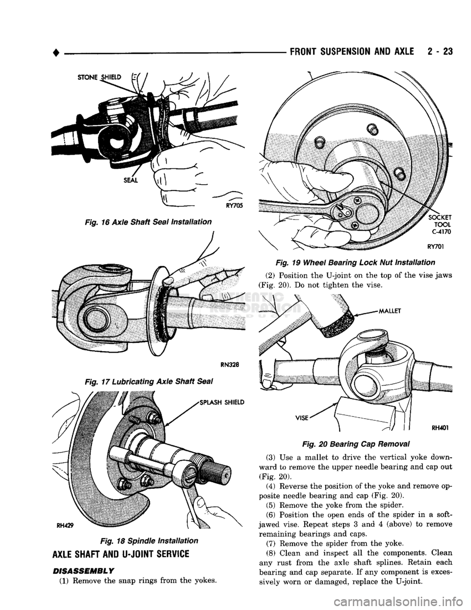
RN328
Fig.
17 Lubricating Axle Shaft
Seal
Fig.
18
Spindle
Installation
AXLE SHAFT AND
U-JOINT
SERVICE DISASSEMBLY
(1) Remove the snap rings from the yokes.
Fig.
19
Wheel
Bearing Lock Nut
Installation
(2)
Position the U-joint on the top of the vise jaws
(Fig. 20). Do not tighten the vise.
Fig.
20 Bearing Cap
Removal
(3)
Use a mallet to drive the vertical yoke down
ward to remove the upper needle bearing and cap out (Fig. 20).
(4)
Reverse the position of the yoke and remove op
posite needle bearing and cap (Fig. 20).
(5)
Remove the yoke from the spider.
(6)
Position the open ends of the spider in a soft-
jawed vise. Repeat steps 3 and 4 (above) to remove remaining bearings and caps.
(7) Remove the spider from the yoke.
(8) Clean and inspect all the components. Clean
any rust from the axle shaft splines. Retain each
bearing and cap separate. If any component is exces sively worn or damaged, replace the U-joint.
Page 84 of 1502
•
FRONT SUSPENSION
AND
AXLE
2 - 31
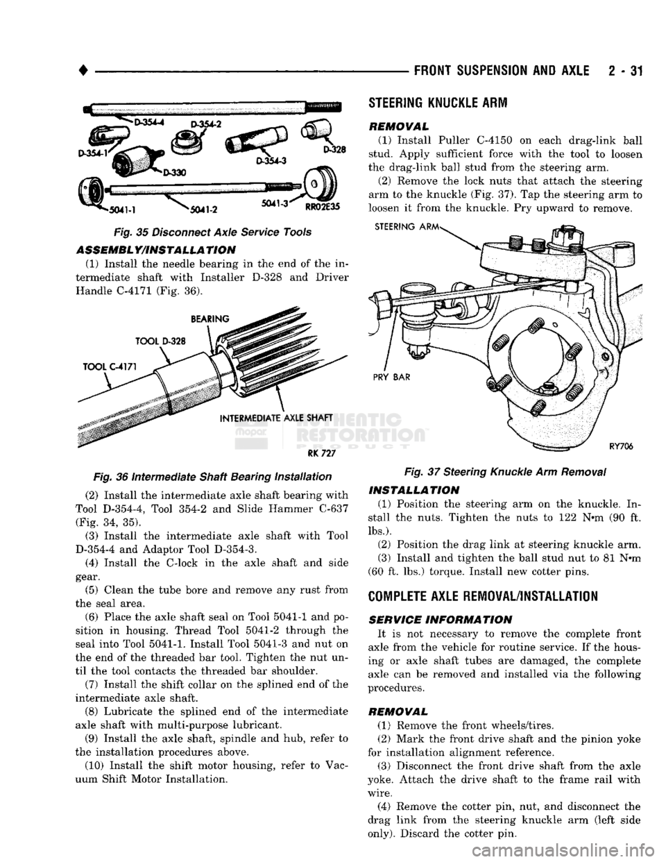
Fig. 35 Disconnect Axle Service Tools ASSEMBLY/INSTALLATION
(1) Install the needle bearing in the end of the in
termediate shaft with Installer D-328 and Driver Handle C-4171 (Fig. 36).
RK
727
Fig. 36 Intermediate Shaft Bearing installation (2) Install the intermediate axle shaft bearing with
Tool D-354-4, Tool 354-2 and Slide Hammer C-637 (Fig. 34, 35).
(3) Install the intermediate axle shaft with Tool
D-354-4 and Adaptor Tool D-354-3.
(4) Install the C-lock in the axle shaft and side
gear.
(5) Clean the tube bore and remove any rust from
the seal area.
(6) Place the axle shaft seal on Tool 5041-1 and po
sition in housing. Thread Tool 5041-2 through the
seal into Tool
5041-1.
Install Tool 5041-3 and nut on
the end of the threaded bar tool. Tighten the nut un
til the tool contacts the threaded bar shoulder.
(7) Install the shift collar on the splined end of the
intermediate axle shaft.
(8) Lubricate the splined end of the intermediate
axle shaft with multi-purpose lubricant.
(9) Install the axle shaft, spindle and hub, refer to
the installation procedures above. (10) Install the shift motor housing, refer to Vac
uum Shift Motor Installation.
STEERING
KNUCKLE
ARM
REMOVAL
(1) Install Puller C-4150 on each drag-link ball
stud. Apply sufficient force with the tool to loosen
the drag-link ball stud from the steering arm.
(2) Remove the lock nuts that attach the steering
arm to the knuckle (Fig. 37). Tap the steering arm to
loosen it from the knuckle. Pry upward to remove. Fig. 37 Steering Knuckle Arm Removal
INSTALLATION
(1) Position the steering arm on the knuckle. In
stall the nuts. Tighten the nuts to 122 N«m (90 ft.
lbs.).
(2) Position the drag link at steering knuckle arm.
(3) Install and tighten the ball stud nut to 81 N*m
(60 ft. lbs.) torque. Install new cotter pins.
COMPLETE
AXLE REMOVAL/INSTALLATION
SERVICE
INFORMATION
It is not necessary to remove the complete front
axle from the vehicle for routine service. If the hous
ing or axle shaft tubes are damaged, the complete axle can be removed and installed via the following
procedures.
REMOVAL (1) Remove the front wheels/tires.
(2) Mark the front drive shaft and the pinion yoke
for installation alignment reference.
(3) Disconnect the front drive shaft from the axle
yoke. Attach the drive shaft to the frame rail with
wire.
(4) Remove the cotter pin, nut, and disconnect the
drag link from the steering knuckle arm (left side
only).
Discard the cotter pin.
Page 102 of 1502
•
FRONT
SUSPENSION
AND
AXLE
2 - 49
MODEL
60 FRONT
AXLE
INDEX
page
Axle Shaft
and
U-Joint
Service
55
Complete Axle Removal/Installation
59
Differential
Assembly
63
Differential
Disassembly
59
Drain
and Refill
51
General
Information
49
Locking
Hubs,
Spindle
and
Axle Shaft
52
Lubricant
51
page
Pinion Gear Depth Measurement
and
Adjustment
with
Tool
Set
C-758-D6
68
Pinion Gear Depth Measurement
and
Adjustment
with
Tool
Set
D-116
66
Pinion Shaft Seal
51
Specifications
75
Steering Knuckle, Upper
and
Lower Kingpins
. . . 56
GENERAL
INFORMATION
Model
60
front axles
(Fig. 1)
consist
of an
iron cen
ter casting with axle shaft tubes extending from
ei
ther side.
The
tubes
are
pressed into
and
welded
to
the differential housing. The integral type housing, hypoid gear design
has
the centerline
of the
pinion
set
below
the
centerline of
the
ring gear. The axles
are
equipped with full-floating axle
shafts,
meaning that loads
are
supported
by the
spin
dles attached
to the
steering knuckles.
Two
tapered
opposed roller bearings allow
the hub and
rotor
as
sembly
to
rotate
on the
spindle. The removable, stamped steel cover provides
a
means
for
inspection
and
service without removing
the complete axle from
the
vehicle.
A small, stamped metal axle gear ratio identifica
tion
tag is
attached
to the
housing cover
via one of
the cover bolts. This
tag
also identifies
the
number
of
ring gear
and
pinion gear teeth.
The differential case
is a
one-piece design.
The dif
ferential pinion mate shaft
is
retained with
a
roll
pin. Differential bearing preload
and
ring gear back lash
are
adjusted
by the use of
shims located between
the differential bearing cones
and
case.
Page 108 of 1502
•
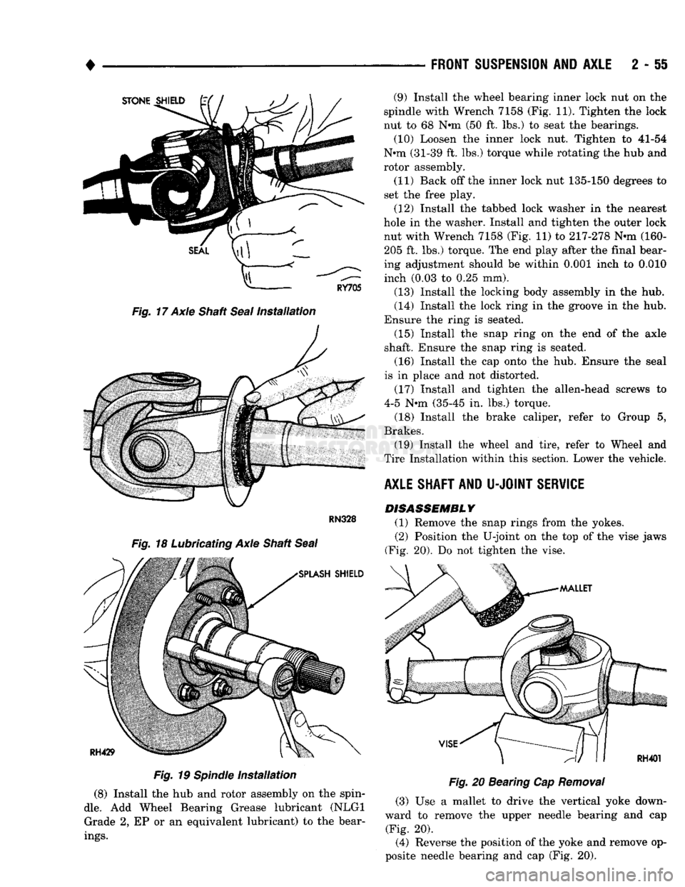
Fig.
17 Axle Shaft
Seal
Installation
Fig.
19
Spindle
Installation
(8) Install the hub and rotor assembly on the spin
dle.
Add Wheel Bearing Grease lubricant (NLGI Grade 2, EP or an equivalent lubricant) to the bear
ings.
FRONT
SUSPENSION
AND
AXLE
2 - 51
Fig.
20 Bearing Cap
Removal
(3) Use a mallet to drive the vertical yoke down
ward to remove the upper needle bearing and cap (Fig. 20).
(4) Reverse the position of the yoke and remove op
posite needle bearing and cap (Fig. 20). (9) Install the wheel bearing inner lock nut on the
spindle with Wrench 7158 (Fig. 11). Tighten the lock
nut to 68 N*m (50 ft. lbs.) to seat the bearings. (10) Loosen the inner lock nut. Tighten to 41-54
N*m (31-39 ft. lbs.) torque while rotating the hub and
rotor assembly.
(11) Back off the inner lock nut 135-150 degrees to
set the free play.
(12) Install the tabbed lock washer in the nearest
hole in the washer. Install and tighten the outer lock nut with Wrench 7158 (Fig. 11) to 217-278 N-m (160-205 ft. lbs.) torque. The end play after the final bear
ing adjustment should be within 0.001 inch to 0.010 inch (0.03 to 0.25 mm).
(13) Install the locking body assembly in the hub.
(14) Install the lock ring in the groove in the hub.
Ensure the ring is seated. (15) Install the snap ring on the end of the axle
shaft. Ensure the snap ring is seated.
(16) Install the cap onto the hub. Ensure the seal
is in place and not distorted.
(17) Install and tighten the allen-head screws to
4-5 N-m (35-45 in. lbs.) torque.
(18) Install the brake caliper, refer to Group 5,
Brakes. (19) Install the wheel and tire, refer to Wheel and
Tire Installation within this section. Lower the vehicle.
AXLE SHAFT AND
U-JOINT
SERVICE DISASSEMBLY
(1) Remove the snap rings from the yokes.
(2) Position the U-joint on the top of the vise jaws
(Fig. 20). Do not tighten the vise.
Page 109 of 1502
2
- 56
FRONT
SUSPENSION
AND
AXLE
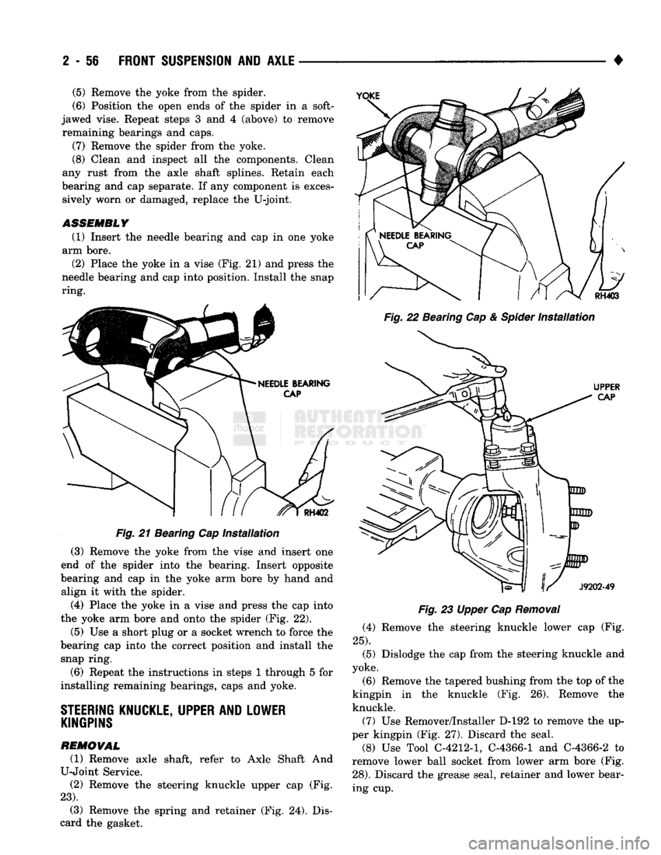
Fig. 21 Bearing Cap installation (3) Remove the yoke from the vise and insert one
end of the spider into the bearing. Insert opposite
bearing and cap in the yoke arm bore by hand and align it with the spider.
(4) Place the yoke in a vise and press the cap into
the yoke arm bore and onto the spider (Fig. 22).
(5)
Use a short plug or a socket wrench to force the
bearing cap into the correct position and install the snap ring.
(6) Repeat the instructions in steps 1 through 5 for
installing remaining bearings, caps and yoke.
STEERING
KNUCKLE, UPPER AND LOWER KINGPINS
REMOVAL
(1) Remove axle shaft, refer to Axle Shaft And
U-Joint Service. (2) Remove the steering knuckle upper cap (Fig.
23).
(3) Remove the spring and retainer (Fig. 24). Dis
card the gasket. •
Fig. 22 Bearing Cap & Spider Installation
Fig. 23 Upper Cap Removal (4) Remove the steering knuckle lower cap (Fig.
25).
(5) Dislodge the cap from the steering knuckle and
yoke.
(6) Remove the tapered bushing from the top of the
kingpin in the knuckle (Fig. 26). Remove the knuckle.
(7) Use Remover/Installer D-192 to remove the up
per kingpin (Fig, 27). Discard the seal.
(8) Use Tool C-4212-1, C-4366-1 and C-4366-2 to
remove lower ball socket from lower arm bore (Fig.
28).
Discard the grease seal, retainer and lower bear
ing cup.
(5)
Remove the yoke from the spider.
(6) Position the open ends of the spider in a soft-
jawed vise. Repeat steps 3 and 4 (above) to remove remaining bearings and caps.
(7) Remove the spider from the yoke.
(8) Clean and inspect all the components. Clean
any rust from the axle shaft splines. Retain each
bearing and cap separate. If any component is exces sively worn or damaged, replace the U-joint.
ASSEMBLY
(1) Insert the needle bearing and cap in one yoke
arm bore.
(2) Place the yoke in a vise (Fig. 21) and press the
needle bearing and cap into position. Install the snap
ring.
Page 112 of 1502
•
TAPERED
BUSHING
J9202-53
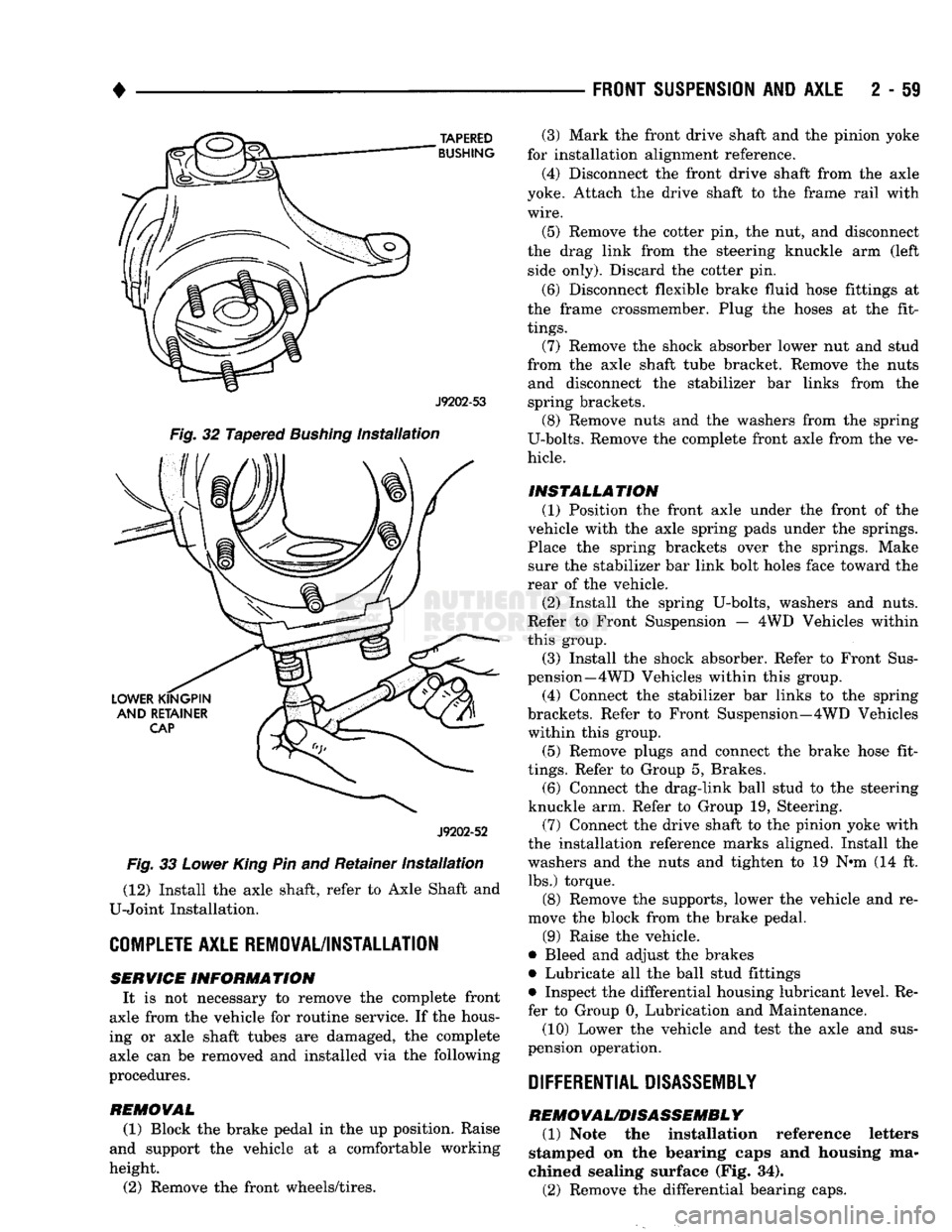
Fig.
32 Tapered
Bushing
Installation
J9202-52
Fig.
33
Lower
King
Pin and Retainer
Installation
(12) Install the axle shaft, refer to Axle Shaft and
U-Joint Installation.
COMPLETE
AXLE REMOVAL/INSTALLATION SERVICE
INFORMATION
It is not necessary to remove the complete front
axle from the vehicle for routine service. If the hous
ing or axle shaft tubes are damaged, the complete axle can be removed and installed via the following
procedures.
REMOVAL
(1) Block the brake pedal in the up position. Raise
and support the vehicle at a comfortable working
height.
(2) Remove the front wheels/tires.
FRONT SUSPENSION
AND
AXLE
2 - 59
(3) Mark the front drive shaft and the pinion yoke
for installation alignment reference.
(4) Disconnect the front drive shaft from the axle
yoke. Attach the drive shaft to the frame rail with
wire.
(5) Remove the cotter pin, the nut, and disconnect
the drag link from the steering knuckle arm (left side only). Discard the cotter pin.
(6) Disconnect flexible brake fluid hose fittings at
the frame crossmember. Plug the hoses at the fit
tings.
(7) Remove the shock absorber lower nut and stud
from the axle shaft tube bracket. Remove the nuts and disconnect the stabilizer bar links from the
spring brackets. (8) Remove nuts and the washers from the spring
U-bolts. Remove the complete front axle from the ve
hicle.
INSTALLATION (1) Position the front axle under the front of the
vehicle with the axle spring pads under the springs.
Place the spring brackets over the springs. Make sure the stabilizer bar link bolt holes face toward the
rear of the vehicle.
(2) Install the spring U-bolts, washers and nuts.
Refer to Front Suspension — 4WD Vehicles within
this group. (3) Install the shock absorber. Refer to Front Sus
pension—4 WD Vehicles within this group.
(4) Connect the stabilizer bar links to the spring
brackets. Refer to Front Suspension—4WD Vehicles within this group.
(5) Remove plugs and connect the brake hose fit
tings.
Refer to Group 5, Brakes. (6) Connect the drag-link ball stud to the steering
knuckle arm. Refer to Group 19, Steering. (7) Connect the drive shaft to the pinion yoke with
the installation reference marks aligned. Install the
washers and the nuts and tighten to 19 N-m (14 ft. lbs.) torque.
(8) Remove the supports, lower the vehicle and re
move the block from the brake pedal.
(9) Raise the vehicle.
• Bleed and adjust the brakes
• Lubricate all the ball stud fittings
• Inspect the differential housing lubricant level. Re
fer to Group 0, Lubrication and Maintenance.
(10) Lower the vehicle and test the axle and sus
pension operation.
DIFFERENTIAL DISASSEMBLY
REMOVAL/DISASSEMBLY
(1) Note the installation reference letters
stamped on the bearing caps and housing ma
chined sealing surface (Fig. 34).
(2) Remove the differential bearing caps.