service DODGE TRUCK 1993 Service Manual PDF
[x] Cancel search | Manufacturer: DODGE, Model Year: 1993, Model line: TRUCK, Model: DODGE TRUCK 1993Pages: 1502, PDF Size: 80.97 MB
Page 209 of 1502
5
- 22
BRAKES
POWER BRAKE
VACUUM
PUMP—DIESEL ENGINE
INDEX
page
General
Information
22
Low
Vacuum
Warning
Switch
22
Pump
Adapter
Replacement
. 25
Vacuum
Pump
Diagnosis
..................
23
Vacuum
Pump
Operation
..................
23
page
Vacuum
Pump
Replacement
24
Vacuum
Pump
Serviceability
22
Vacuum—Steering
Pump
Assembly
Installation
. . 26
Vacuum—Steering
Pump
Assembly
Removal
... 23
GENERAL
INFORMATION
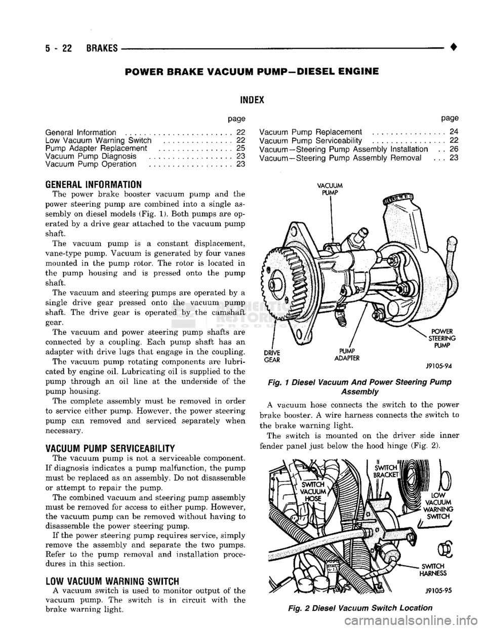
The power brake booster vacuum pump
and the
power steering pump
are
combined into
a
single
as
sembly
on
diesel models
(Fig. 1).
Both pumps
are op
erated
by a
drive gear attached
to the
vacuum pump shaft. The vacuum pump
is a
constant displacement,
vane-type pump. Vacuum
is
generated
by
four vanes
mounted
in the
pump rotor.
The
rotor
is
located
in
the pump housing
and is
pressed onto
the
pump shaft. The vacuum
and
steering pumps
are
operated
by a
single drive gear pressed onto
the
vacuum pump
shaft.
The
drive gear
is
operated
by the
camshaft
gear. The vacuum
and
power steering pump shafts
are
connected
by a
coupling. Each pump shaft
has an
adapter with drive lugs that engage
in the
coupling. The vacuum pump rotating components
are
lubri
cated
by
engine
oil.
Lubricating
oil is
supplied
to the
pump through
an oil
line
at the
underside
of the
pump housing. The complete assembly must
be
removed
in
order
to service either pump. However,
the
power steering
pump
can
removed
and
serviced separately when necessary.
VACUUM
PUMP
SERVICEABILITY
The vacuum pump
is not a
serviceable component.
If diagnosis indicates
a
pump malfunction,
the
pump must
be
replaced
as an
assembly.
Do not
disassemble
or attempt
to
repair
the
pump.
The combined vacuum
and
steering pump assembly
must
be
removed
for
access
to
either pump. However,
the vacuum pump
can be
removed without having
to
disassemble
the
power steering pump. If
the
power steering pump requires service, simply
remove
the
assembly
and
separate
the two
pumps. Refer
to the
pump removal
and
installation procedures
in
this section.
LOW
VACUUM
WARNING
SWITCH
A vacuum switch
is
used
to
monitor output
of the
vacuum pump.
The
switch
is in
circuit with
the
brake warning light.
VACUUM
PUMP
DRIVE
GEAR
PUMP
ADAPTER
POWER
STEERING
PUMP
J9105-94
Fig.
1
Diesel
Vacuum
And
Power
Steering
Pump
Assembly
A vacuum hose connects
the
switch
to the
power
brake booster.
A
wire harness connects
the
switch
to
the brake warning light.
The switch
is
mounted
on the
driver side inner
fender panel just below
the
hood hinge
(Fig. 2),
b
LOW
VACUUM
WARNING
SWITCH
SWITCH
HARNESS
J9105-95
Fig.
2
Diesel
Vacuum
Switch
Location
Page 212 of 1502
•
BRAKES
5 - 25
ADAPTER
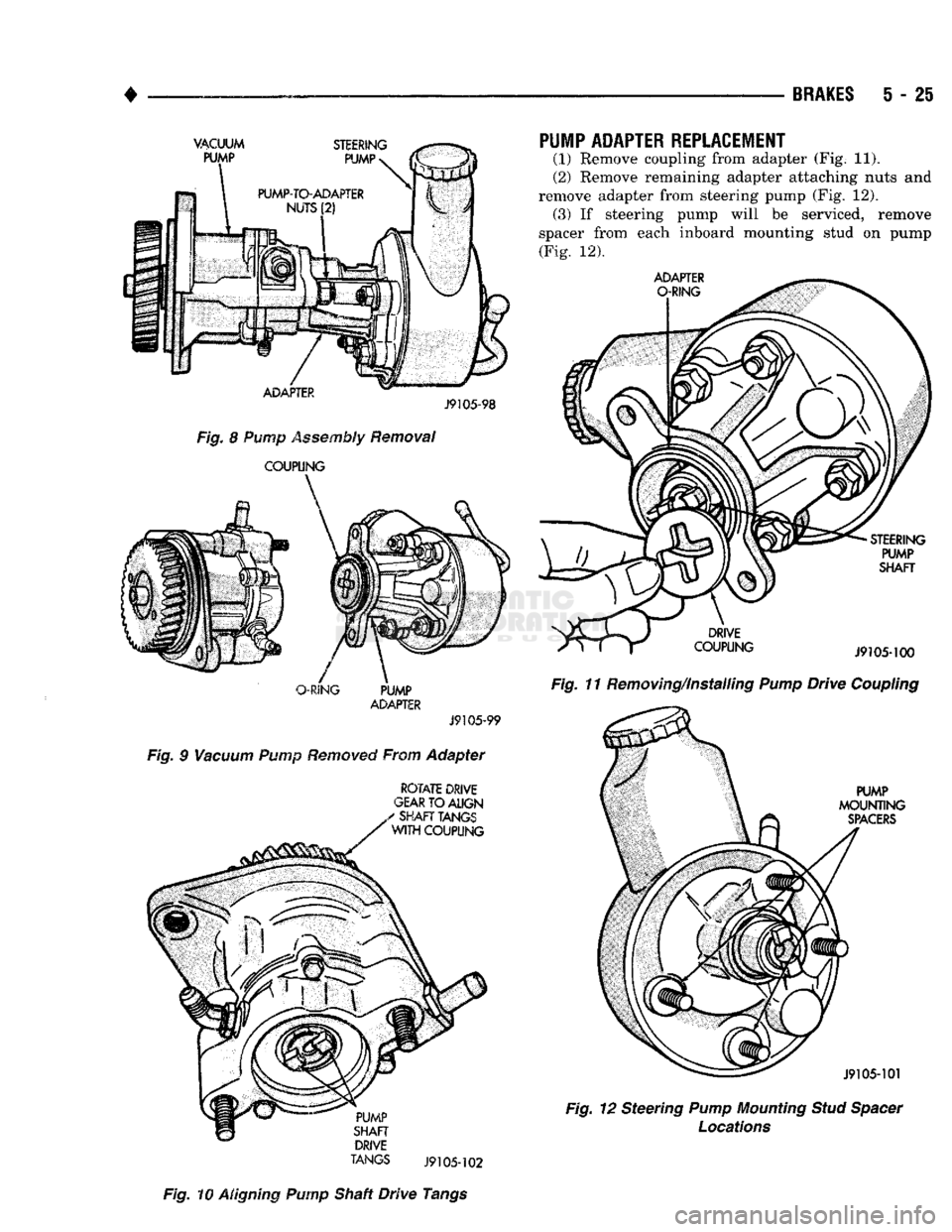
J9105-98
Fig.
8 Pump Assembly Removal
COUPLING
O-RING
PUMP
ADAPTER
J9105-99
Fig.
9
Vacuum
Pump
Removed
From Adapter
ROTATE
DRIVE
GEAR
TO
ALIGN
TANGS
J9105-102
Fig.
10 Aligning Pump Shaft Drive Tangs
PUMP ADAPTER REPLACEMENT
(1) Remove coupling from adapter (Fig. 11).
(2) Remove remaining adapter attaching nuts and
remove adapter from steering pump (Fig. 12). (3) If steering pump will be serviced, remove
spacer from each inboard mounting stud on pump (Fig, 12).
Fig.
11 Removing/Installing
Pump
Drive
Coupling
Fig.
12 Steering
Pump
Mounting
Stud
Spacer
Locations
Page 214 of 1502
•
BRAKES
5 - 27 CHRYSLER
DISC
BRAKE
INDEX
page
Caliper
Installation
. 33
Caliper Overhaul
32
Caliper Removal
31
Disc
Brake Inspection
29
Disc
Brakeshoe
Installation
, 31
GENERAL
INFORMATION
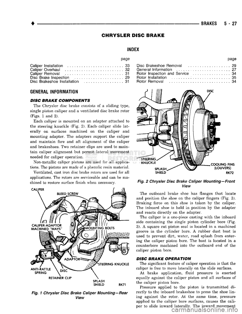
DISC BRAKE COMPONENTS The Chrysler disc brake consists of a sliding type,
single piston caliper and a ventilated disc brake rotor
(Figs.
1 and 2).
Each caliper is mounted on an adapter attached to
the steering knuckle (Fig. 2). Each- caliper slide lat erally on surfaces machined on the caliper and
mounting adapter. The adapters support the caliper and maintain fore and aft alignment of the caliper
and brakeshoes. Two retainer clips are used to main
tain caliper alignment but permit lateral movement needed for caliper operation.
Non-metallic caliper pistons are used for all applica
tions.
The pistons are made of a phenolic resin material.
Ventilated, cast iron disc brake rotors are used for all
applications. The rotors are serviceable and can be ma
chined to restore surface finish when necessary. RETAINER CLIP
SPLASH
SHIELD RK71
Fig. 1 Chrysler Disc Brake Caliper Mounting—Rear View
page
Disc
Brakeshoe Removal
29
General
Information
....................... 27
Rotor Inspection
and
Service
................ 34
Rotor
Installation
. 35
Rotor Removal
34
SHIELD
RK72
Fig. 2 Chrysler Disc Brake Caliper Mounting—Front View The outboard brake shoe has flanges that locate
and position the shoe on the caliper fingers (Fig. 3).
Braking force on this shoe is taken by the caliper.
The inboard shoe is held in position by the adapter and reacts directly on the adapter.
The caliper is a one-piece casting with the inboard
side containing the single piston cylinder bore (Fig.
3).
A square cut piston seal is located in a machined
groove in the cylinder bore. A rubber dust boot is used to prevent dirt, water, road splash from enter
ing the caliper piston bore. The boot is located in a
counterbore machined into the outboard end of the
caliper piston bore.
DISC BRAKE OPERATION The significant feature of caliper operation is that the
caliper is free to move laterally on the slide surfaces. At brake application, fluid pressure is exerted
equally against the caliper piston and all surfaces of
the caliper piston bore.
Pressure applied to the piston is transmitted di
rectly to the inboard brakeshoe to press the shoe lin ing against the rotor. At the same time, pressure applied to the caliper bore surfaces, causes the cali
per to slide inward laterally. The inward movement
Page 216 of 1502
•
BRAKES
5 - 29 presses the outboard shoe lining against the opposite
side of the rotor to complete braking action.
The application or release of fluid pressure causes
only a very slight movement of the caliper and pis
ton. At brake release, the piston and caliper return
to the non-applied position.
The brakeshoes do not retract an appreciable dis
tance from the rotor. The minimal running clearance
between the lining and rotor provides improved re sponse and reduced pedal travel. It also helps in pre
venting dirt and foreign material from lodging
between the shoe and rotor surfaces.
DISC
BRAKE
LINING WEAR COMPENSATION
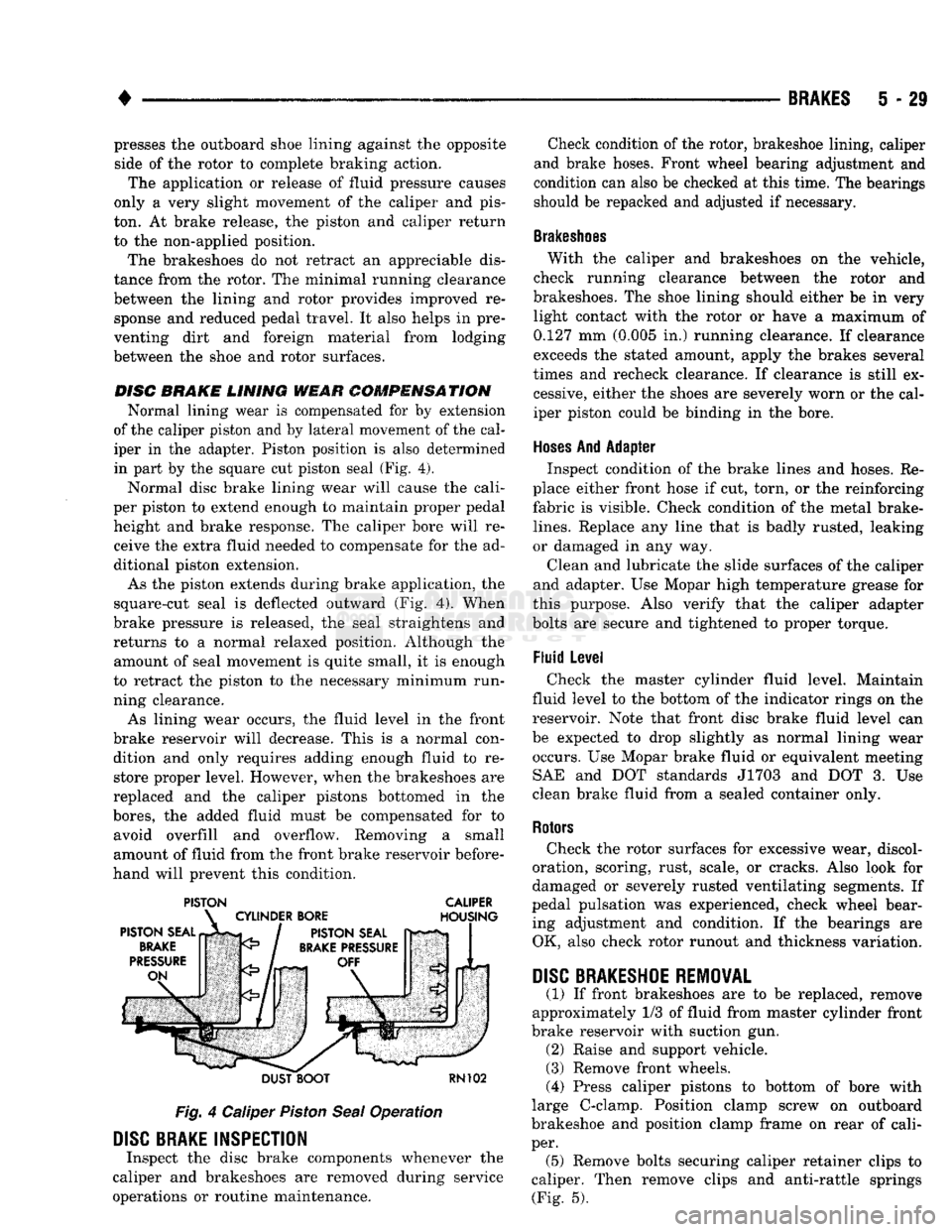
Normal lining wear is compensated for by extension
of the caliper piston and by lateral movement of the cal
iper in the adapter. Piston position is also determined
in part by the square cut piston seal (Fig. 4).
Normal disc brake lining wear will cause the cali
per piston to extend enough to maintain proper pedal height and brake response. The caliper bore will receive the extra fluid needed to compensate for the ad
ditional piston extension.
As the piston extends during brake application, the
square-cut seal is deflected outward (Fig. 4). When
brake pressure is released, the seal straightens and
returns to a normal relaxed position. Although the amount of seal movement is quite small, it is enough
to retract the piston to the necessary minimum run
ning clearance.
As lining wear occurs, the fluid level in the front
brake reservoir will decrease. This is a normal con dition and only requires adding enough fluid to restore proper level. However, when the brakeshoes are
replaced and the caliper pistons bottomed in the
bores,
the added fluid must be compensated for to avoid overfill and overflow. Removing a small
amount of fluid from the front brake reservoir before
hand will prevent this condition.
PISTON CALIPER
DUST BOOT
RN102
Fig.
4 Caliper
Piston
Seal
Operation
DISC
BRAKE INSPECTION
Inspect the disc brake components whenever the
caliper and brakeshoes are removed during service
operations or routine maintenance. Check condition of the rotor, brakeshoe lining, caliper
and brake hoses. Front wheel bearing adjustment and
condition can also be checked at this time. The bearings
should be repacked and adjusted if necessary.
Brakeshoes
With the caliper and brakeshoes on the vehicle,
check running clearance between the rotor and
brakeshoes. The shoe lining should either be in very light contact with the rotor or have a maximum of
0.127 mm (0.005 in.) running clearance. If clearance
exceeds the stated amount, apply the brakes several
times and recheck clearance. If clearance is still ex cessive, either the shoes are severely worn or the cal
iper piston could be binding in the bore.
Hoses
And Adapter Inspect condition of the brake lines and hoses. Re
place either front hose if cut, torn, or the reinforcing
fabric is visible. Check condition of the metal brake-
lines.
Replace any line that is badly rusted, leaking
or damaged in any way.
Clean and lubricate the slide surfaces of the caliper
and adapter. Use Mopar high temperature grease for
this purpose. Also verify that the caliper adapter
bolts are secure and tightened to proper torque.
Fluid Level Check the master cylinder fluid level. Maintain
fluid level to the bottom of the indicator rings on the
reservoir. Note that front disc brake fluid level can
be expected to drop slightly as normal lining wear occurs. Use Mopar brake fluid or equivalent meeting SAE and DOT standards J1703 and DOT 3. Use
clean brake fluid from a sealed container only.
Rotors
Check the rotor surfaces for excessive wear, discol
oration, scoring, rust, scale, or cracks. Also look for
damaged or severely rusted ventilating segments. If
pedal pulsation was experienced, check wheel bear ing adjustment and condition. If the bearings are OK, also check rotor runout and thickness variation.
DISC
BRAKESHOE
REMOVAL
(1) If front brakeshoes are to be replaced, remove
approximately 1/3 of fluid from master cylinder front
brake reservoir with suction gun. (2) Raise and support vehicle.
(3) Remove front wheels.
(4) Press caliper pistons to bottom of bore with
large C-clamp. Position clamp screw on outboard
brakeshoe and position clamp frame on rear of cali
per. (5) Remove bolts securing caliper retainer clips to
caliper. Then remove clips and anti-rattle springs (Fig. 5).
Page 221 of 1502
5
- 34
BRAKES
•
boot
>TALLir TOOL
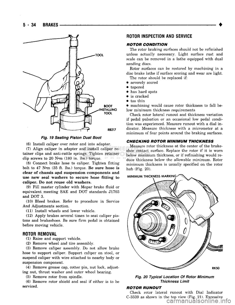
Fig.
19 Seating
Piston
Dust
Boot
(6) Install caliper over rotor and into adapter.
(7) Align caliper in adapter and install caliper re
tainer clips and anti-rattle springs. Tighten retainer clip screws to 20 N*m (180 in. lbs.) torque.
(8) Connect brake hose to caliper. Tighten fitting
bolt to 47 N»m (35 ft. lbs.) torque. Be sure hose is clear of chassis and suspension components and
use new seal washers to secure hose fitting to caliper. Do not reuse old washers.
(9) Fill master cylinder with Mopar brake fluid or
equivalent meeting SAE and DOT standards J1703 and DOT 3.
(10) Bleed brakes. Refer to procedure in Service
And Adjustments section.
(11) Install wheels and lower vehicle.
(12) Apply brakes several times to seat caliper pis
tons and brakeshoes. Be sure firm pedal is obtained
before moving vehicle.
ROTOR REMOVAL
(1) Raise and support vehicle.
(2) Remove wheel and tire assembly.
(3) Remove caliper assembly. Do not allow brake
hose to support caliper. Support caliper on stool, or suspend caliper with wire attached to nearby body or
suspension component. (4) Remove grease cap, cotter pin, nut lock, adjust
ing nut, thrust washer and outer wheel bearing. (5) Remove rotor from spindle.
(6) Remove rotor shield and seal if either is to be
serviced.
ROTOR
INSPECTION AND
SERVICE
rotor condition The rotor braking surfaces should not be refinished
unless actually necessary. Light surface rust and scale can be removed in a lathe equipped with dual
sanding discs.
Rotor surfaces can be restored by machining in a
disc brake lathe if surface scoring and wear are light.
The rotor should be replaced if:
• severely scored
• tapered
• has hard spots
• is cracked
• too thin • machining would cause rotor thickness to fall be
low minimum thickness requirements Check rotor lateral runout and thickness variation
if pedal pulsation or an occasional low pedal condi
tion was experienced. Measure runout with a dial in dicator. Measure thickness with a micrometer at a
minimum of four points around the braking surfaces.
CHECKING
ROTOR
MINIMUM
THICKNESS
Measure rotor thickness at the center of the brake-
shoe contact surface. Replace the rotor if it is worn
below minimum thickness, or if refinishing would re duce thickness below the allowable minimum. Rotor
minimum thickness is usually specified on the rotor
hub (Fig. 20).
Fig.
20 Typical Location Of Rotor
Minimum
Thickness
Limit
ROTOR RUNOUT Check rotor lateral runout with Dial Indicator
C-3339 as shown in the top view (Fig. 21). Excessive
Page 224 of 1502
•
BRAKES
5 - 37
BENDIX
DISC
BRAKE
INDEX
page
Caliper Overhaul
41
Disc
Brake Inspection
39
Disc
Brakeshoe
Installation
40
Disc
Brakeshoe Removal
. 39
GENERAL
SERVICE
INFORMATION
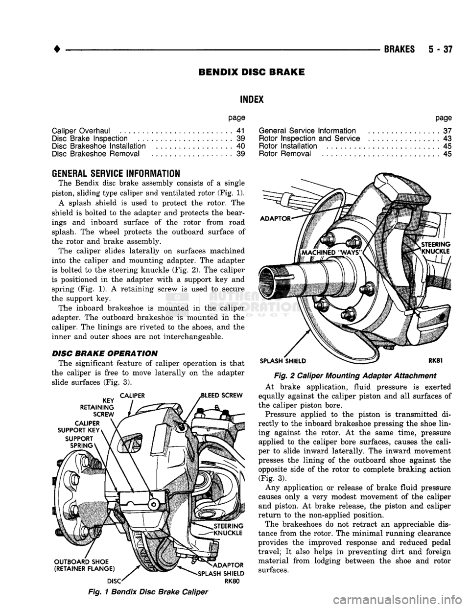
The Bendix disc brake assembly consists of a single
piston, sliding type caliper and ventilated rotor (Fig. 1). A splash shield is used to protect the rotor. The
shield is bolted to the adapter and protects the bear
ings and inboard surface of the rotor from road splash. The wheel protects the outboard surface of
the rotor and brake assembly. The caliper slides laterally on surfaces machined
into the caliper and mounting adapter. The adapter
is bolted to the steering knuckle (Fig. 2). The caliper
is positioned in the adapter with a support key and spring (Fig. 1). A retaining screw is used to secure
the support key. The inboard brakeshoe is mounted in the caliper
adapter. The outboard brakeshoe is mounted in the
caliper. The linings are riveted to the shoes, and the
inner and outer shoes are not interchangeable.
DISC
BRAKE OPERATION
The significant feature of caliper operation is that
the caliper is free to move laterally on the adapter slide surfaces (Fig. 3).
Fig.
1
Bendix
Disc
Brake Caliper
page
General Service
Information
37
Rotor Inspection
and
Service
................ 43
Rotor
Installation
45
Rotor Removal
45
Fig.
2 Caliper
Mounting
Adapter Attachment
At brake application, fluid pressure is exerted
equally against the caliper piston and all surfaces of
the caliper piston bore.
Pressure applied to the piston is transmitted di
rectly to the inboard brakeshoe pressing the shoe lin ing against the rotor. At the same time, pressure applied to the caliper bore surfaces, causes the cali
per to slide inward laterally. The inward movement
presses the lining of the outboard shoe against the
opposite side of the rotor to complete braking action (Fig. 3).
Any application or release of brake fluid pressure
causes only a very modest movement of the caliper and piston. At brake release, the piston and caliper
return to the non-applied position.
The brakeshoes do not retract an appreciable dis
tance from the rotor. The minimal running clearance
provides the improved response and reduced pedal
travel; It also helps in preventing dirt and foreign
material from lodging between the shoe and rotor surfaces.
Page 226 of 1502
BRAKES
5 - 39
DISC BRAKE LINING WEAR COMPENSATION
Normal lining wear is compensated for by exten
sion of the caliper piston and by lateral movement of
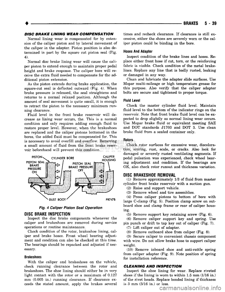
the caliper in the adapter. Piston position is also de termined in part by the square cut piston seal (Fig.
4).
Normal disc brake lining wear will cause the cali
per piston to extend enough to maintain proper pedal height and brake response. The caliper bore will receive the extra fluid needed to compensate for the ad
ditional piston extension.
As the piston extends during brake application, the
square-cut seal is deflected outward (Fig. 4). When
brake pressure is released, the seal straightens and returns to a normal relaxed position. Although the amount of seal movement is quite small, it is enough
to retract the piston to the necessary minimum run ning clearance. Fluid level in the front brake reservoir will de
crease as lining wear occurs, the. This is a normal
condition and only requires adding enough fluid to
restore proper level. However, when the brakeshoes are replaced and the caliper pistons bottomed in the
bores,
the added fluid must be compensated for. This is necessary to avoid overfill and overflow. Removing a small amount of fluid from the front brake reser
voir beforehand will prevent this condition.
Fig.
4 Caliper
Piston
Seal
Operation
DISC
BRAKE INSPECTION
Inspect the disc brake components whenever the
caliper and brakeshoes are removed during service
operations or routine maintenance. Check condition of the rotor, brakeshoe lining, cal
iper and brake hoses. Front wheel bearing adjust
ment and condition can also be checked at this time.
The bearings should be repacked and adjusted if nec essary.
Brakeshoes
With the caliper and brakeshoes on the vehicle,
check running clearance between the rotor and
brakeshoes. The shoe lining should either be in very light contact with the rotor or a maximum of 0.127
mm (0.005 in.) running clearance. If clearance exceeds the stated amount, apply the brakes several times and recheck clearance. If clearance is still ex
cessive, either the shoes are severely worn or the cal
iper piston could be binding in the bore.
Hoses
And Adapter Inspect condition of the brake lines and hoses. Re
place either front hose if cut, torn, or the reinforcing
fabric is visible. Check condition of the metal brake-
lines.
Replace any line that is badly rusted, leaking
or damaged in any way.
Clean and lubricate the adapter slide surfaces. Use
Mopar multi-mileage or high temperature grease for
this purpose. Also verify that the caliper adapter
bolts are secure and tightened to proper torque.
Fluid Level Check the master cylinder fluid level. Maintain
fluid level to the bottom of the indicator rings on the
reservoir. Note that front brake fluid level can be ex
pected to drop slightly as normal lining wear occurs.
Use Mopar brake fluid or equivalent meeting SAE and DOT standards J1703 and DOT 3. Use clean
brake fluid from a sealed container only.
Rotors
Check rotor surfaces for excessive wear, discolora
tion, scoring, rust, scale, or cracks. Also look for damaged or severely rusted ventilating segments. If
pedal pulsation was experienced, check wheel bear ing adjustment and condition. If the bearings are OK, also check rotor runout and thickness variation.
DISC
BRAKESHOE REMOVAL
(1) Remove approximately 1/3 of fluid from master
cylinder front brake reservoir with a suction gun. (2) Raise and support vehicle.
(3) Remove wheel and tire assemblies.
(4) Press caliper pistons to bottom of bore with
large C-clamp (Fig. 5). Position clamp screw on out
board shoe and clamp frame or rear of caliper hous ing. (5) Remove support key retaining screw (Fig. 6).
(6) Remove caliper support key and spring. Use
pin punch or drift to tap key out of caliper (Fig. 7). (7) Lift caliper out of adapter. (8) Remove outboard shoe from caliper (Fig. 8).
(9) Secure caliper to convenient chassis component
with wire. Do not allow brake hose to support caliper weight. (10) Remove inboard shoe and anti-rattle spring
from caliper adapter (Fig. 9). Note position of spring
for installation reference.
CLEANING AND INSPECTION Inspect the shoe lining for wear. Replace riveted
shoes if the lining is worn to within 1.5 mm (1/16 in.)
of the rivet heads. Replace bonded lining if thickness is 3 mm (3/16 in.) or less.
Page 230 of 1502
•
BRAKES
5 - 43
CAMPER
ASSEMBLY
(1) Mount caliper in vise equipped with protective
jaws.
Do not overtighten vise. Excessive pressure could cause bore distortion and piston binding. (2) Lubricate new piston seal and piston bore with
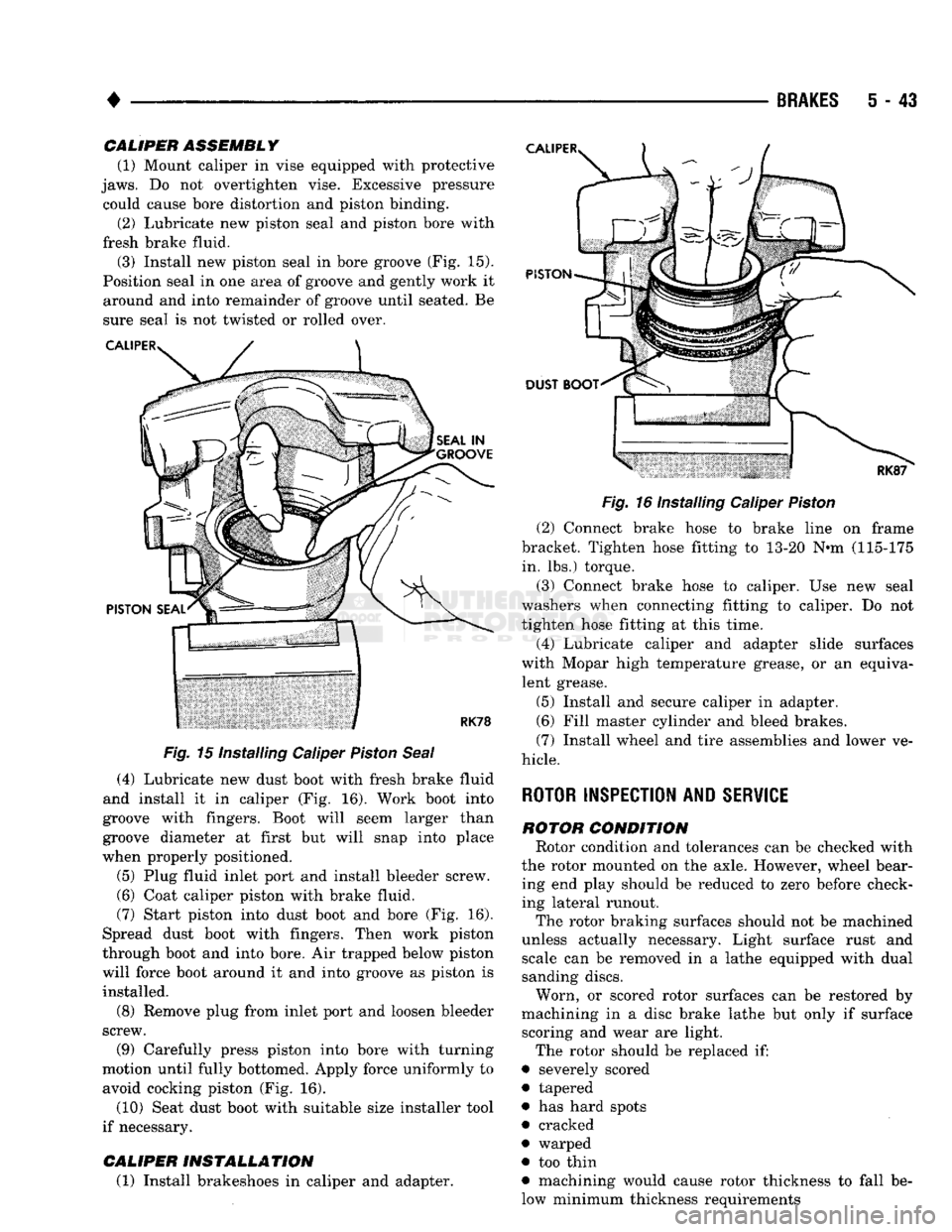
fresh brake fluid. (3) Install new piston seal in bore groove (Fig. 15).
Position seal in one area of groove and gently work it around and into remainder of groove until seated. Be
sure seal is not twisted or rolled over.
Fig.
15 Installing Caliper
Piston
Seal
(4) Lubricate new dust boot with fresh brake fluid
and install it in caliper (Fig. 16). Work boot into
groove with fingers. Boot will seem larger than
groove diameter at first but will snap into place
when properly positioned.
(5) Plug fluid inlet port and install bleeder screw. (6) Coat caliper piston with brake fluid.
(7) Start piston into dust boot and bore (Fig. 16).
Spread dust boot with fingers. Then work piston
through boot and into bore. Air trapped below piston
will force boot around it and into groove as piston is installed.
(8) Remove plug from inlet port and loosen bleeder
screw.
(9) Carefully press piston into bore with turning
motion until fully bottomed. Apply force uniformly to avoid cocking piston (Fig. 16).
(10) Seat dust boot with suitable size installer tool
if necessary.
CALIPER
INSTALLATION
(1) Install brakeshoes in caliper and adapter.
Fig.
16 Installing Caliper
Piston
(2) Connect brake hose to brake line on frame
bracket. Tighten hose fitting to 13-20 N«m (115-175 in. lbs.) torque.
(3) Connect brake hose to caliper. Use new seal
washers when connecting fitting to caliper. Do not
tighten hose fitting at this time.
(4) Lubricate caliper and adapter slide surfaces
with Mopar high temperature grease, or an equiva lent grease.
(5) Install and secure caliper in adapter.
(6) Fill master cylinder and bleed brakes.
(7) Install wheel and tire assemblies and lower ve
hicle.
ROTOR INSPECTION AND
SERVICE
ROTOR
CONDITION
Rotor condition and tolerances can be checked with
the rotor mounted on the axle. However, wheel bear ing end play should be reduced to zero before check
ing lateral runout.
The rotor braking surfaces should not be machined
unless actually necessary. Light surface rust and scale can be removed in a lathe equipped with dual
sanding discs.
Worn, or scored rotor surfaces can be restored by
machining in a disc brake lathe but only if surface scoring and wear are light.
The rotor should be replaced if:
• severely scored
• tapered
• has hard spots
• cracked
• warped
• too thin
• machining would cause rotor thickness to fall be
low minimum thickness requirements
Page 232 of 1502
•
BRAKES
5 - 45 multaneously with dual cutter heads. Equipment ca
pable of machining only one side at a time will
produce a tapered rotor. The lathe should also be equipped with a grinder
attachment or dual sanding discs for final cleanup or
light refinishing.
If the rotor surfaces only need minor cleanup of
rust, scale, or scoring, use abrasive discs to clean up
the rotor surfaces. However, when a rotor is scored or
worn, machining with cutting tools will be required.
CAUTION:
Do not refinish a rotor if
machining
would
cause
the rotor to
fall
below minimum allow
able
thickness.
ROTOR REMOVAL
(1) Raise and support front of vehicle.
(2) Remove wheel and tire assemblies.
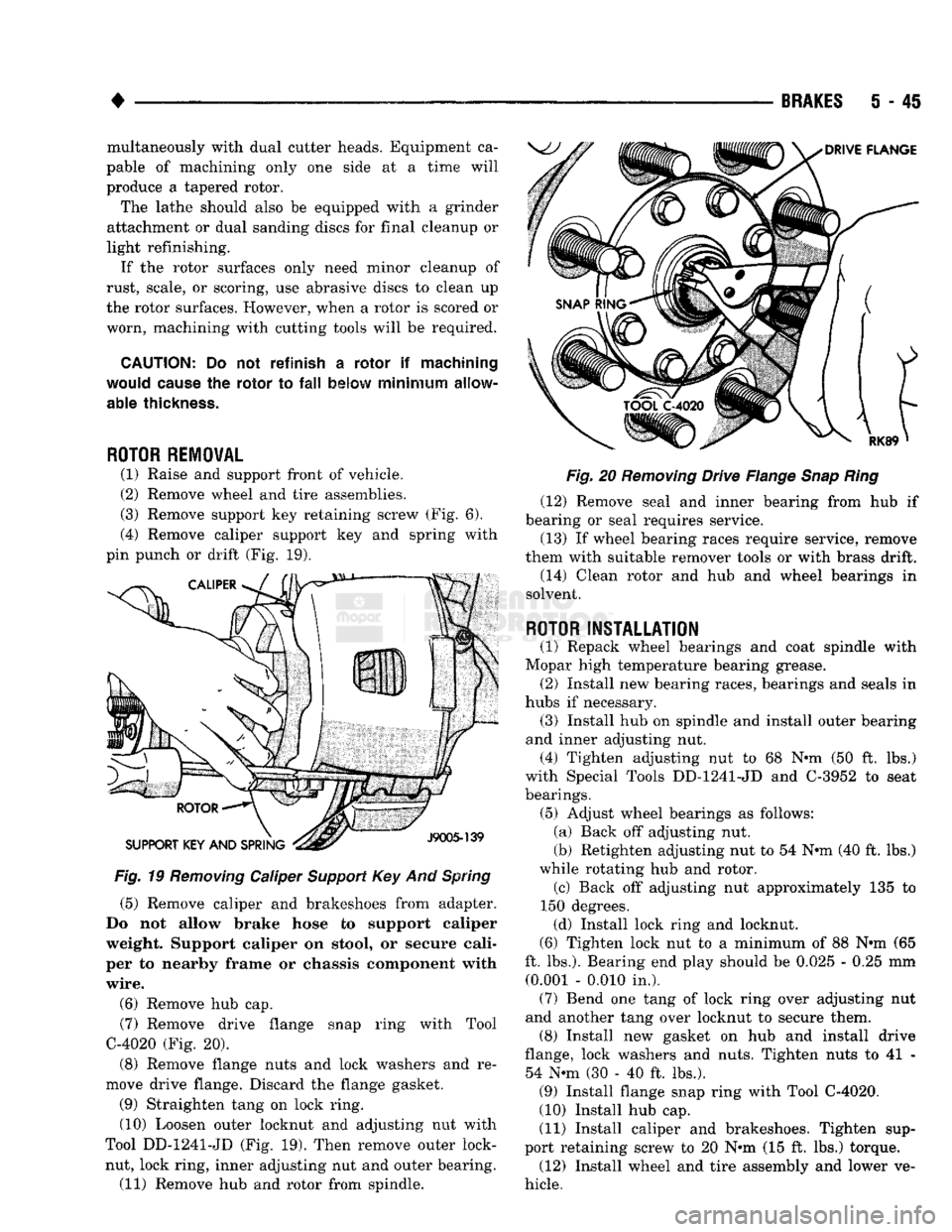
(3) Remove support key retaining screw (Fig. 6).
(4) Remove caliper support key and spring with
pin punch or drift (Fig. 19).
Fig.
19
Removing
Caliper
Support
Key And
Spring
(5) Remove caliper and brakeshoes from adapter.
Do not allow brake hose to support caliper
weight. Support caliper on stool, or secure cali
per to nearby frame or chassis component with
wire.
(6) Remove hub cap. (7) Remove drive flange snap ring with Tool
C-4020 (Fig. 20).
(8) Remove flange nuts and lock washers and re
move drive flange. Discard the flange gasket.
(9) Straighten tang on lock ring. (10) Loosen outer locknut and adjusting nut with
Tool DD-1241-JD (Fig. 19). Then remove outer lock- nut, lock ring, inner adjusting nut and outer bearing. (11) Remove hub and rotor from spindle.
Fig.
20
Removing
Drive Flange
Snap
Ring
(12) Remove seal and inner bearing from hub if
bearing or seal requires service.
(13) If wheel bearing races require service, remove
them with suitable remover tools or with brass drift. (14) Clean rotor and hub and wheel bearings in
solvent.
ROTOR
INSTALLATION
(1) Repack wheel bearings and coat spindle with
Mopar high temperature bearing grease. (2) Install new bearing races, bearings and seals in
hubs if necessary. (3) Install hub on spindle and install outer bearing
and inner adjusting nut. (4) Tighten adjusting nut to 68 Nrni (50 ft. lbs.)
with Special Tools DD-1241-JD and C-3952 to seat
bearings. (5) Adjust wheel bearings as follows: (a) Back off adjusting nut.
(b) Retighten adjusting nut to 54 N*m (40 ft. lbs.)
while rotating hub and rotor. (c) Back off adjusting nut approximately 135 to
150 degrees. (d) Install lock ring and locknut.
(6) Tighten lock nut to a minimum of 88 N»m (65
ft. lbs.). Bearing end play should be 0.025 - 0.25 mm (0.001 - 0.010 in.). (7) Bend one tang of lock ring over adjusting nut
and another tang over locknut to secure them. (8) Install new gasket on hub and install drive
flange, lock washers and nuts. Tighten nuts to 41 - 54 N«m (30 - 40 ft. lbs.). (9) Install flange snap ring with Tool C-4020.
(10) Install hub cap.
(11) Install caliper and brakeshoes. Tighten sup
port retaining screw to 20 Nnn (15 ft. lbs.) torque. (12) Install wheel and tire assembly and lower ve
hicle.
Page 235 of 1502
5
- 48
BRAKES
•
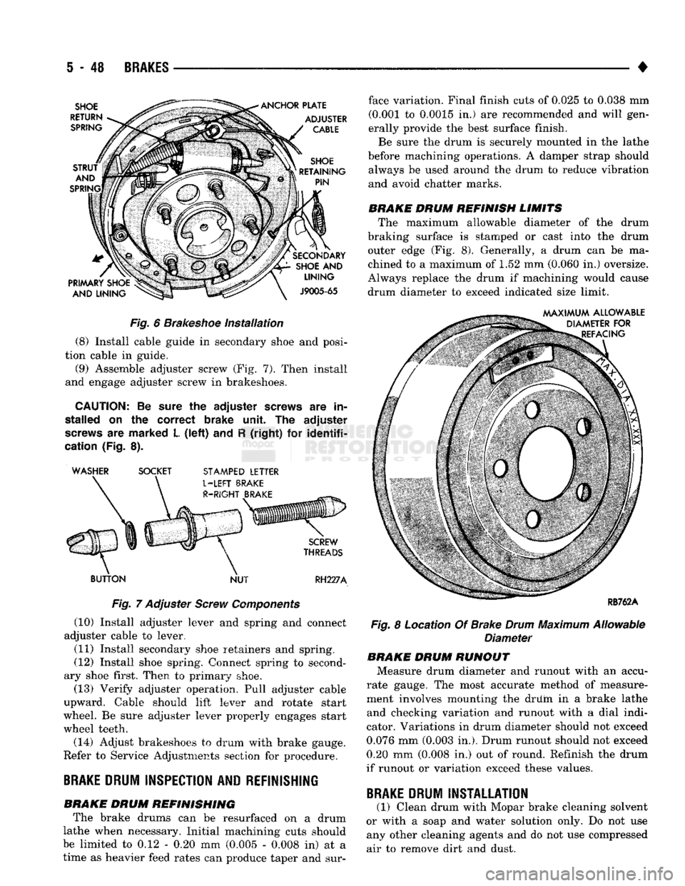
Fig.
6
Brakeshoe
Installation
(8) Install cable guide in secondary shoe and posi
tion cable in guide. (9) Assemble adjuster screw (Fig. 7). Then install
and engage adjuster screw in brakeshoes.
CAUTION:
Be sure the
adjuster
screws
are in
stalled
on the
correct
brake unit. The
adjuster
screws
are marked L
(left)
and R
(right)
for
identifi
cation
(Fig. 8). ' WASHER SOCKET
STAMPED
LETTER
BUTTON
NUT
RH227A
Fig.
7 Adjuster
Screw
Components
(10) Install adjuster lever and spring and connect
adjuster cable to lever.
(11) Install secondary shoe retainers and spring.
(12) Install shoe spring. Connect spring to second
ary shoe first. Then to primary shoe. (13) Verify adjuster operation. Pull adjuster cable
upward. Cable should lift lever and rotate start
wheel. Be sure adjuster lever properly engages start
wheel teeth.
(14) Adjust brakeshoes to drum with brake gauge.
Refer to Service Adjustments section for procedure.
BRAKE
DRUM
INSPECTION
AND
REFINISHING
BRAKE DRUM REFINISHING The brake drums can be resurfaced on a drum
lathe when necessary. Initial machining cuts should
be limited to 0.12 - 0.20 mm (0.005 - 0.008 in) at a
time as heavier feed rates can produce taper and sur face variation. Final finish cuts of 0.025 to 0.038 mm
(0.001 to 0.0015 in.) are recommended and will gen
erally provide the best surface finish.
Be sure the drum is securely mounted in the lathe
before machining operations. A damper strap should always be used around the drum to reduce vibration
and avoid chatter marks.
BRAKE DRUM REFINISH LIMITS The maximum allowable diameter of the drum
braking surface is stamped or cast into the drum outer edge (Fig. 8). Generally, a drum can be ma
chined to a maximum of 1.52 mm (0.060 in.) oversize.
Always replace the drum if machining would cause
drum diameter to exceed indicated size limit.
Fig.
8 Location Of Brake
Drum
Maximum Allowable
Diameter BRAKE DRUM RUNOUT
Measure drum diameter and runout with an accu
rate gauge. The most accurate method of measure
ment involves mounting the driim in a brake lathe
and checking variation and runout with a dial indi
cator. Variations in drum diameter should not exceed
0.076 mm (0.003 in.). Drum runout should not exceed 0.20 mm (0.008 in.) out of round. Refinish the drum
if runout or variation exceed these values.
BRAKE
DRUM
INSTALLATION
(1) Clean drum with Mopar brake cleaning solvent
or with a soap and water solution only. Do not use any other cleaning agents and do not use compressed
air to remove dirt and dust.