coolant temperature DODGE TRUCK 1993 Service Workshop Manual
[x] Cancel search | Manufacturer: DODGE, Model Year: 1993, Model line: TRUCK, Model: DODGE TRUCK 1993Pages: 1502, PDF Size: 80.97 MB
Page 862 of 1502
MULTI-PORT
FUEL
INJECTION
(MPI)—GENERAL DIAGNOSIS—EXCEPT DIESEL
INDEX
page
Camshaft Position Sensor Testing
............
52
Charge
Air
Temperature Sensor Test
52
Coolant Temperature Sensor Test
52
Crankshaft Position Sensor Test
54
Diagnostic Trouble Code (DTC)
60
DRB
II
Scan
Tool
........................
60
Fuel
Injector
Test
57
Fuel Pump Pressure Test
57
Idle
Air
Control
(IAC) Motor Test
55
Manifold Absolute Pressure (MAP) Sensor Test
. 53
page
On-Board
Diagnostics (OBD)
59
Oxygen
(02)
Sensor Heating Element Test
54
Powertrain
Control
Module (PCM) 60-Way Connector
. 47
Relays—Operation/Testing
56
Starter
Motor Relay Test
57
System
Schematics
. 47
Throttle
Position Sensor (TPS) Test
54
Visual Inspection
43
VISUAL
INSPECTION
A visual inspection
for
loose, disconnected,
or
incor
rectly routed wires
and
hoses should
be
made. This should
be
done before attempting
to
diagnose
or
ser
vice
the
fuel injection system.
A
visual check will
help spot these faults
and
save unnecessary test
and
diagnostic time.
A
thorough visual inspection will
in
clude
the
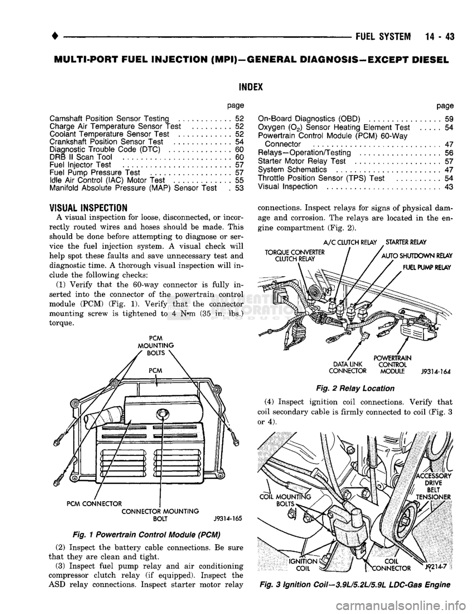
following checks: (1) Verify that
the
60-way connector
is
fully
in
serted into
the
connector
of the
powertrain control
module
(PCM) (Fig. 1).
Verify that
the
connector
mounting screw
is
tightened
to 4 N#m (35 in. lbs.)
torque.
PCM
MOUNTING
BOLTS
PCM CONNECTOR CONNECTOR MOUNTING BOLT
J9314-165
Fig.
1
Powertrain Control
Module
(PCM) (2) Inspect
the
battery cable connections.
Be
sure
that they
are
clean
and
tight.
(3) Inspect fuel pump relay
and air
conditioning
compressor clutch relay
(if
equipped). Inspect
the
ASD relay connections. Inspect starter motor relay connections. Inspect relays
for
signs
of
physical dam
age
and
corrosion.
The
relays
are
located
in the en
gine compartment
(Fig. 2).
TORQUE CONVERTER
CLUTCH RELAY
A/C
CLUTCH RELAY STARTER RELAY
AUTO SHUTDOWN RELAY FUEL PUMP RELAY POWERTRAIN
DATA UNK CONTROL
CONNECTOR MODULE
J9314-164
Fig.
2
Relay Location (4) Inspect ignition coil connections. Verify that
coil secondary cable
is
firmly connected
to
coil (Fig.
3
or 4).
|X COIL
frCONNECTOR J9214-7
Fig.
3
Ignition Coil—3.9U5.2L/5.9L
LDC-Gas
Engine
Page 864 of 1502
•
FUEL
SYSTEM
14-45 (12) Inspect accelerator cable, transmission throt
tle cable (if equipped) and cruise control cable con
nections (if equipped). Check their connections to the
throttle arm of throttle body for any binding or re strictions (Fig. 8).
Fig.
8
Throttle
Body
Cables—Typical
(13) If equipped with vacuum brake booster, verify
that vacuum booster hose is firmly connected to fit
ting on intake manifold. Also check connection to
brake vacuum booster.
(14) Inspect the air cleaner inlet and air filter ele
ment for dirt or restrictions.
(15) Inspect radiator grille area, radiator fins and
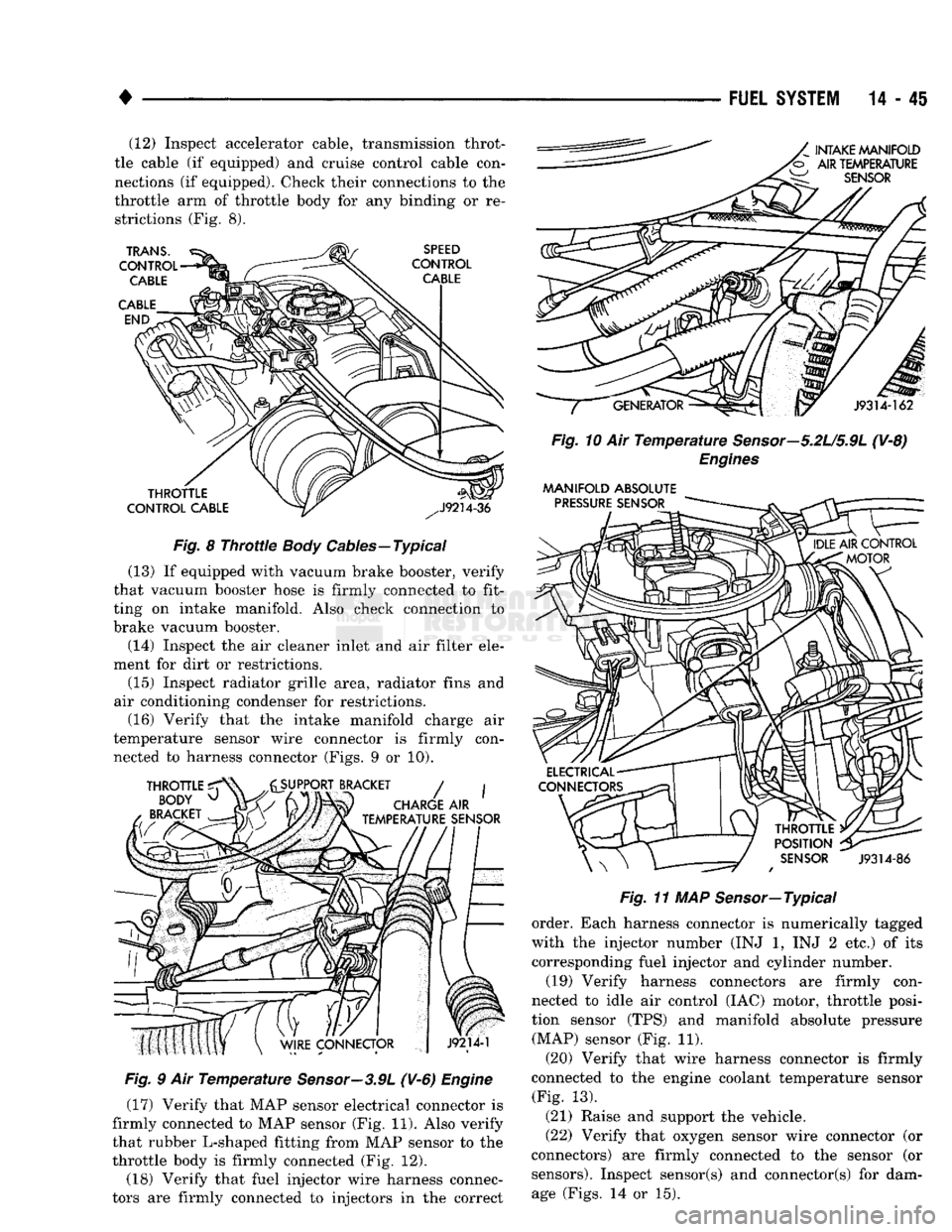
air conditioning condenser for restrictions. (16) Verify that the intake manifold charge air
temperature sensor wire connector is firmly con nected to harness connector (Figs. 9 or 10).
Fig.
9 Air
Temperature
Sensor—3.9L
(V-6)
Engine
(17) Verify that MAP sensor electrical connector is
firmly connected to MAP sensor (Fig. 11). Also verify
that rubber L-shaped fitting from MAP sensor to the
throttle body is firmly connected (Fig. 12).
(18) Verify that fuel injector wire harness connec
tors are firmly connected to injectors in the correct
Fig.
10 Air
Temperature
Sensor—5.2U5.9L
(V-8)
Engines
MANIFOLD
ABSOLUTE
Fig.
11 MAP Sensor—Typical
order. Each harness connector is numerically tagged
with the injector number (INJ 1, INJ 2 etc.) of its
corresponding fuel injector and cylinder number.
(19) Verify harness connectors are firmly con
nected to idle air control (IAC) motor, throttle posi
tion sensor (TPS) and manifold absolute pressure (MAP) sensor (Fig. 11).
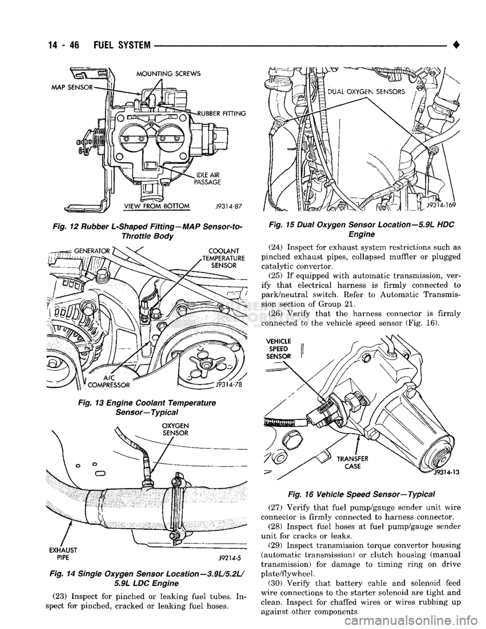
(20) Verify that wire harness connector is firmly
connected to the engine coolant temperature sensor (Fig. 13).
(21) Raise and support the vehicle.
(22) Verify that oxygen sensor wire connector (or
connectors) are firmly connected to the sensor (or sensors). Inspect sensor(s) and connector(s) for damage (Figs. 14 or 15).
Page 865 of 1502
14
- 46
FUEL
SYSTEM
Fig.
12
Rubber
L-Shaped
Fitting—MAP
Sensor-to-
Throttie
Body
Fig.
13
Engine
Coolant
Temperature
Sensor—
Typical
EXHAUST
~~
PIPE
J9214-5
Fig.
14
Single
Oxygen
Sensor
Location-3.9U5.2L/ 5.9L LDC
Engine
(23) Inspect for pinched or leaking fuel tubes. In
spect for pinched, cracked or leaking fuel hoses. •
Fig.
15
Dual
Oxygen
Sensor
Location—5.9L HDC
Engine
(24) Inspect for exhaust system restrictions such as
pinched exhaust pipes, collapsed muffler or plugged catalytic convertor.
(25) If equipped with automatic transmission, ver
ify that electrical harness is firmly connected to
park/neutral switch. Refer to Automatic Transmis sion section of Group 21.
(26) Verify that the harness connector is firmly
connected to the vehicle speed sensor (Fig. 16).
Fig.
16 Vehicle
Speed
Sensor—
Typical
(27) Verify that fuel pump/gauge sender unit wire
connector is firmly connected to harness connector.
(28) Inspect fuel hoses at fuel pump/gauge sender
unit for cracks or leaks.
(29) Inspect transmission torque convertor housing
(automatic transmission) or clutch housing (manual
transmission) for damage to timing ring on drive
plate/flywheel. (30) Verify that battery cable and solenoid feed
wire connections to the starter solenoid are tight and clean. Inspect for chaffed wires or wires rubbing up against other components.
Page 867 of 1502
CAV
WIRE
COLOR DESCRIPTION
CAV
WIRE
COLOR DESCRIPTION
1 DG/RD*
MAP SENSOR 37
BK/OR OVERDRIVE LAMP
2 TN/BK*
ENGINE COOLANT TEMPERATURE SENSOR 38 PK/BK INJECTOR DRIVE
#5
3 RD/WT DIRECT BATTERY 39 GY/RD IAC MOTOR
#4
4
BK/LB*
SENSOR RETURN 40 BR/WT
IAC MOTOR
#2
5 BK/WT SIGNAL GROUND 41
BK/DG* OXYGEN SENSOR SIGNAL
6 VT/WT
5-VOLT
OUTPUT
(MAP AND TPS)
42
7 OR
8-VOLT
OUTPUT (DISTRIBUTOR PICK-UP) 43
GY/LB*
TACHOMETER SIGNAL OUTPUT (VEHICLES W/TACHOMETER)
8 44 GY CAMSHAFT POSITION SENSE
9 DB
J2-IGNITION FEED 45
LG SCI RECIEVE
10 R/WT OVERDRIVE OVERRIDE
46 CCD
(-)
11 BK/TN POWER GROUND 47 WT/OR* SPEED SENSOR SIGNAL
12 BK/TN POWER GROUND 48 BR/RD* SPEED CONTROL
SET
SWITCH
13 LB/BR
INJECTOR DRIVER
#4
49
YL/RD* SPEED CONTROL ON/OFF SWITCH
14 YL/WT
INJECTOR DRIVER
#3
50 WT/LG* SPEED CONTROL RESUME SWITCH
15 TN INJECTOR DRIVER
#2
51 DB/YL*
AUTO SHUTDOWN
(ASD)
RELAY
-
RETURN
16
WT/DB*
INJECTOR DRIVER
#1
52 PK/BK
EVAP CANISTER PURGE SOLENOID
17 DB/TN INJECTOR DRIVER
#7
(V-8
ONLY) 53 LG/RD* SPEED CONTROL VENT SOLENOID
18 DB/GY
INJECTOR DRIVER
#8
(V-8
ONLY) 54
OR/BK* SHIFT INDICATOR LIGHT (MANUAL TRANSMISSION ONLY)
19 BK/GY*
IGNITION COIL DRIVER 54
OR/BK* CONVERTOR CLUTCH SOLENOID (AUTO TRANSMISSION)
20 DG
GENERATOR FIELD CONTROL 55
OR/WT OVERDRIVE SOLENOID (AUTO TRANSMISSION ONLY)
21 BK/RD
CHARGE TEMPERATURE SENSOR 56
GY/PK SRI LAMP
(5.9L HDC
ENGINE)
22
OR/DB*
THROTTLE POSITION SENSOR
(TPS)
57
DG/OR ASD SENSE
23 TN/WT
OXYGEN SENSOR SIGNAL
(5.9L HDC
ENGINE) 58 LG/BK
INJECTOR DRIVER
#6
24 GY/BK IGNITION (CAMSHAFT POSITION SENSOR) 59
VT/BK IAC MOTOR
#1
25 PK
,
SCI
TRANSMIT 60
YL/BK* IAC MOTOR
#3
26 CCD
(-:-)
WIRE COLOR CODES LB
LIGHT BLUE
VT VIOLET
27 BR
A/C SWITCH SENSE BK BLACK
LG LIGHT GREEN
WT
WHITE
28 VT A/C SELECT BR BROWN
OR ORANGE
YL YELLOW
29 WT/PK* BRAKE SWITCH
-
DB DARK BLUE PK
PINK *
WITH TRACER
30 BY/YL*
PARK/NEUTRAL SWITCH DG DARK GREEN
RD
RED
31 GY
GRAY TN TAN
32 BK/PK*
MALFUNCTION INDICATOR LAMP
33 TN/RD*
SPEED CONTROL VACUUM SOLENOID CONNECTOR
34 DB/OR* A/C CLUTCH RELAY TERMINAL
|(pcKX>coooop0ffoj'
oooooooooojj
35 GY/YL*
EGR SOLENOID SHOWN W'41
30
50«M#5l31
604
%\
oooooooooo ••ooooooooooj
36 J9314-171
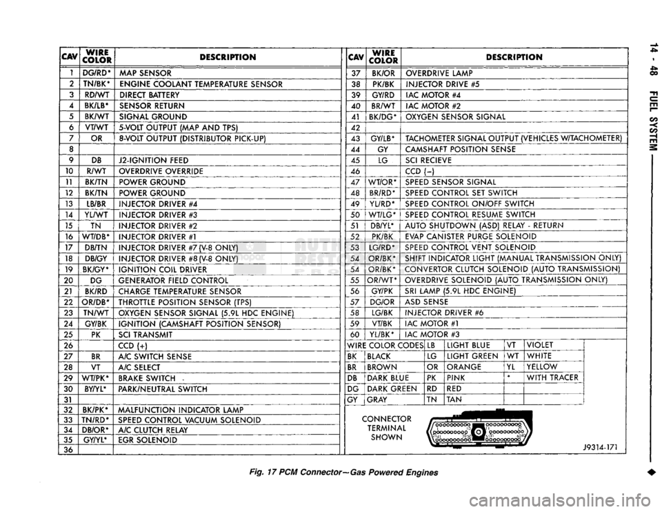
Fig.
17 PCM
Connector—Gas
Powered
Engines
Page 871 of 1502
14-52
FUEL
SYSTEM
•
CAMSHAFT
POSITION
SENSOR
TESTING
Refer to Group 8D, Ignition Systems for testing.
COOLANT
TEMPERATURE
SENSOR
TEST
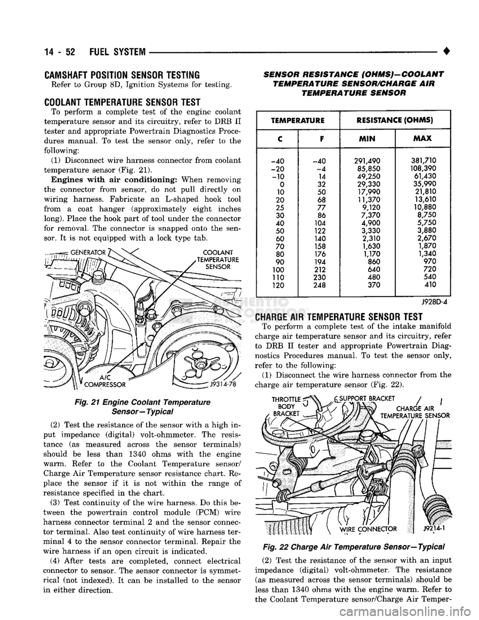
To perform a complete test of the engine coolant
temperature sensor and its circuitry, refer to DRB II
tester and appropriate Powertrain Diagnostics Proce
dures manual. To test the sensor only, refer to the
following: (1) Disconnect wire harness connector from coolant
temperature sensor (Fig. 21). Engines with air conditioning; When removing
the connector from sensor, do not pull directly on
wiring harness. Fabricate an L-shaped hook tool
from a coat hanger (approximately eight inches
long).
Place the hook part of tool under the connector
for removal. The connector is snapped onto the sen sor. It is not equipped with a lock type tab.
Fig.
21
Engine
Coolant
Temperature
Sensor—
Typical
(2) Test the resistance of the sensor with a high in
put impedance (digital) volt-ohmmeter. The resis
tance (as measured across the sensor terminals) should be less than 1340 ohms with the engine
warm. Refer to the Coolant Temperature sensor/ Charge Air Temperature sensor resistance chart. Re
place the sensor if it is not within the range of resistance specified in the chart.
(3) Test continuity of the wire harness. Do this be
tween the powertrain control module (PCM) wire
harness connector terminal 2 and the sensor connec
tor terminal. Also test continuity of wire harness ter
minal 4 to the sensor connector terminal. Repair the
wire harness if an open circuit is indicated.
(4) After tests are completed, connect electrical
connector to sensor. The sensor connector is symmet
rical (not indexed). It can be installed to the sensor in either direction. SENSOR RESISTANCE (OHMS)-COOLANT
TEMPERATURE SENSOR/CHARGE AIR TEMPERATURE SENSOR
TEMPERATURE
RESISTANCE
(OHMS)
C F
MIN MAX
-40 -40 291,490 381,710
-20 -4 85,850 108,390
-10 14 49,250 61,430
0 32 29,330 35,990
10 50 17,990 21,810
20 68 11,370 13,610
25 77 9,120 10,880
30 86 7,370 8,750
40 104 4,900 5,750
50 122 3,330 3,880
60 140 2,310 2,670
70 158 1,630 1,870
80 176 1,170 1,340
90 194 860 970
100 212 640 720
no 230 480 540
120 248 370 410
J928D-4
CHARGE
AIR
TEMPERATURE SENSOR TEST
To perform a complete test of the intake manifold
charge air temperature sensor and its circuitry, refer
to DRB II tester and appropriate Powertrain Diag nostics Procedures manual. To test the sensor only,
refer to the following: (1) Disconnect the wire harness connector from the
charge air temperature sensor (Fig. 22).
Fig.
22
Charge
Air
Temperature
Sensor—Typical
(2) Test the resistance of the sensor with an input
impedance (digital) volt-ohmmeter. The resistance (as measured across the sensor terminals) should be
less than 1340 ohms with the engine warm. Refer to
the Coolant Temperature sensor/Charge Air Temper-
Page 880 of 1502
•
FUEL
SYSTEM
14-61 DIAGNOSTIC TROUBLE CODE {DTC) DESCRIPTION
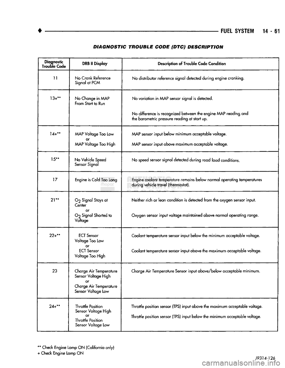
Diagnostic
Trouble
Code DRB II
Display
Description of Trouble Code Condition
11
No
Crank
Reference
Signal at PCM No distributor reference signal detected during engine cranking.
13+**
No Change in
AAAP
From
Start
to Run No variation in MAP sensor signal is detected.
No difference is recognized between the engine
MAP
reading and
the barometric pressure reading at start up.
14+**
MAP
Voltage Too Low
or
MAP
Voltage Too High
MAP
sensor input below minimum acceptable voltage.
MAP sensor input above maximum acceptable voltage.
15**
No Vehicle Speed
Sensor Signal No speed sensor signal detected during road load conditions.
17
Engine is Cold Too Long Engine coolant temperature remains below normal operating temperatures
during vehicle travel (thermostat).
21**
O2
Signal Stays at
Center or
Oo
Signal Shorted to
Voltage Neither rich or lean condition
is
detected from the oxygen sensor input.
Oxygen sensor input voltage maintained above normal operating range.
22+**
ECT
Sensor
Voltage
Too
Low or
ECT
Sensor
Voltage
Too
High Coolant temperature sensor input below the minimum acceptable voltage.
Coolant temperature sensor input above the maximum acceptable voltage.
23
Charge Air Temperature
Sensor Voltage High or
Charge Air Temperature Sensor Voltage Low Charge Air Temperature Sensor input above/below acceptable minimum.
24+**
Throttle Position
Sensor Voltage High or
Throttle Position Sensor Voltage
Low
Throttle position sensor
(TPS)
input above the maximum acceptable voltage.
Throttle position sensor
(TPS)
input below the minimum acceptable voltage.
**
Check Engine Lamp ON (California only)
+ Check Engine Lamp ON J9314-126
Page 883 of 1502
MULTI-PORT
FUEL
INJECTION
(MPI)-COMPONENT
REMOVAL/INSTALLATION
—EXCEPT DIESEL
INDEX
page
Accelerator Pedal
and Throttle
Cable
. 64
Air Conditioning (A/C) Clutch Relay
64
Air
Filter/Filter
Housing
64
Automatic Shut Down (ASD) Relay
. 64
Brake
Switch
64
Camshaft
Position
Sensor
..................
64
Charge
Air
Temperature
Sensor
64
Crankshaft Position
Sensor
64
Engine
Coolant Temperature
Sensor
65
EVAP
Canister Purge Solenoid
65
Fuel
Filter
65
Fuel Filter/Fuel Pressure Regulator—5.9L Engine
. 65
Fuel Injector(S)
67
Fuel Pressure Regulator
67
Fuel Pump Module
68
Fuel Pump Relay
68
ACCELERATOR
PEDAL
AND THROTTLE
CABLE
Refer
to
the
Accelerator Pedal
and
Throttle Cable
section
of
this group
for
removal/installation proce
dures.
AIR
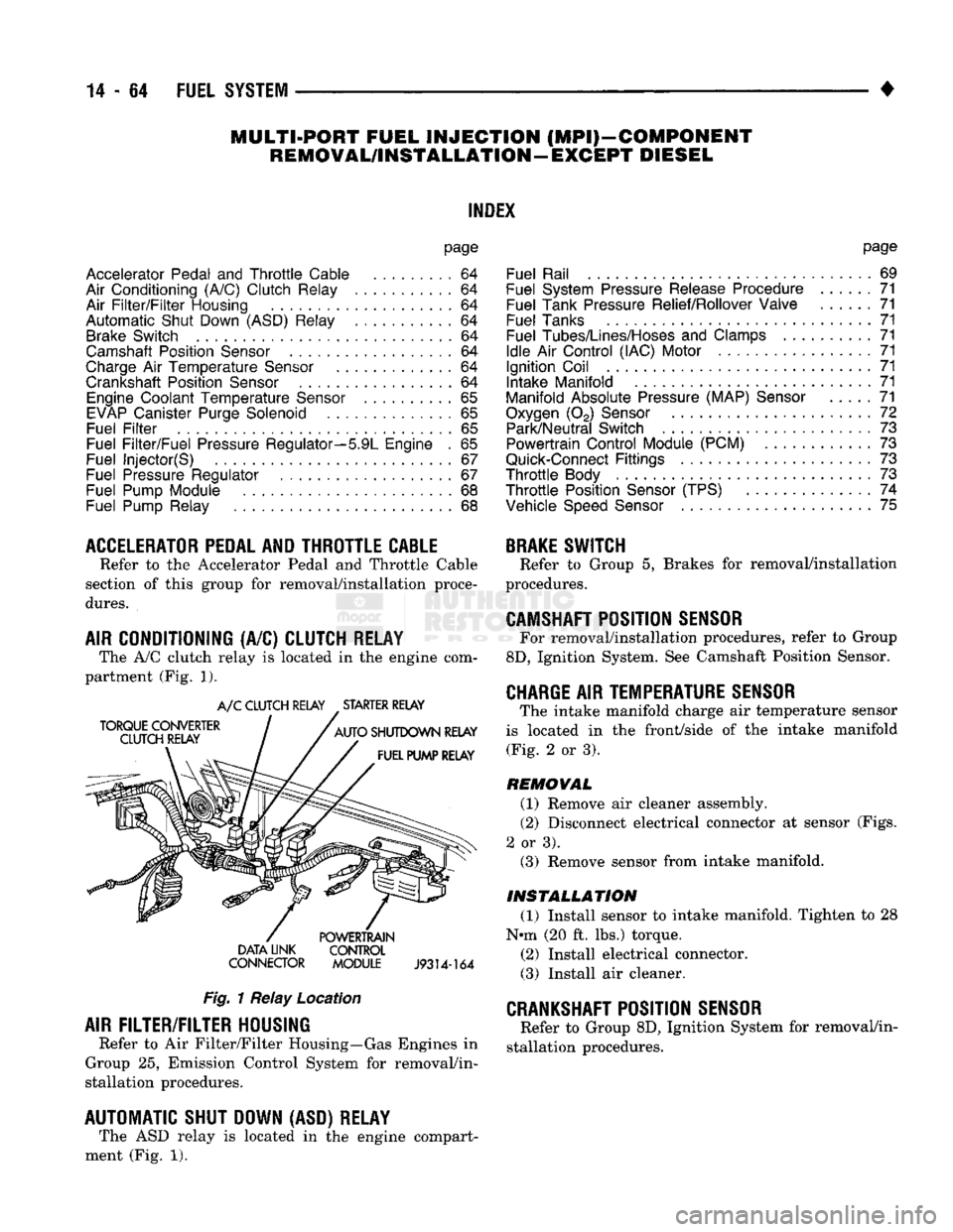
CONDITIONING (A/C) CLUTCH RELAY The A/C clutch relay
is
located
in
the
engine com
partment (Fig.
1).
A/C CLUTCH RELAY STARTER RELAY
DATA LINK CONTROL
CONNECTOR MODULE
J9314-164
Fig.
1 Relay Location
AIR
FILTER/FILTER
HOUSING
Refer
to
Air Filter/Filter Housing—Gas Engines
in
Group
25,
Emission Control System
for
removal/in
stallation procedures.
AUTOMATIC SHUT DOWN (ASD) RELAY The ASD relay
is
located
in
the
engine compart
ment (Fig.
1).
page
Fuel Rail
69
Fuel System Pressure Release Procedure
......
71
Fuel Tank Pressure Relief/Rollover Valve
71
Fuel Tanks
71
Fuel
Tubes/Lines/Hoses
and
Clamps
71
Idle
Air
Control (IAC) Motor
71
Ignition Coil
71
Intake Manifold
71
Manifold Absolute Pressure (MAP)
Sensor
71
Oxygen
(02)
Sensor
72
Park/Neutral Switch
. 73
Powertrain Control Module (PCM)
73
Quick-Connect
Fittings
73
Throttle
Body
73
Throttle
Position
Sensor
(TPS)
......
74
Vehicle
Speed
Sensor
75
BRAKE
SWITCH
Refer
to
Group
5,
Brakes
for
removal/installation
procedures.
CAMSHAFT
POSITION
SENSOR
For removal/installation procedures, refer
to
Group
8D,
Ignition System. See Camshaft Position Sensor.
CHARGE
AIR
TEMPERATURE SENSOR
The intake manifold charge
air
temperature sensor
is located
in the
front/side
of
the
intake manifold (Fig.
2
or
3).
REMOVAL
(1) Remove
air
cleaner assembly.
(2) Disconnect electrical connector
at
sensor (Figs.
2
or
3). (3) Remove sensor from intake manifold.
INSTALLATION
(1) Install sensor
to
intake manifold. Tighten
to 28
Nnn (20
ft.
lbs.) torque.
(2) Install electrical connector.
(3) Install
air
cleaner.
CRANKSHAFT
POSITION
SENSOR
Refer
to
Group 8D, Ignition System
for
removal/in
stallation procedures.
Page 884 of 1502
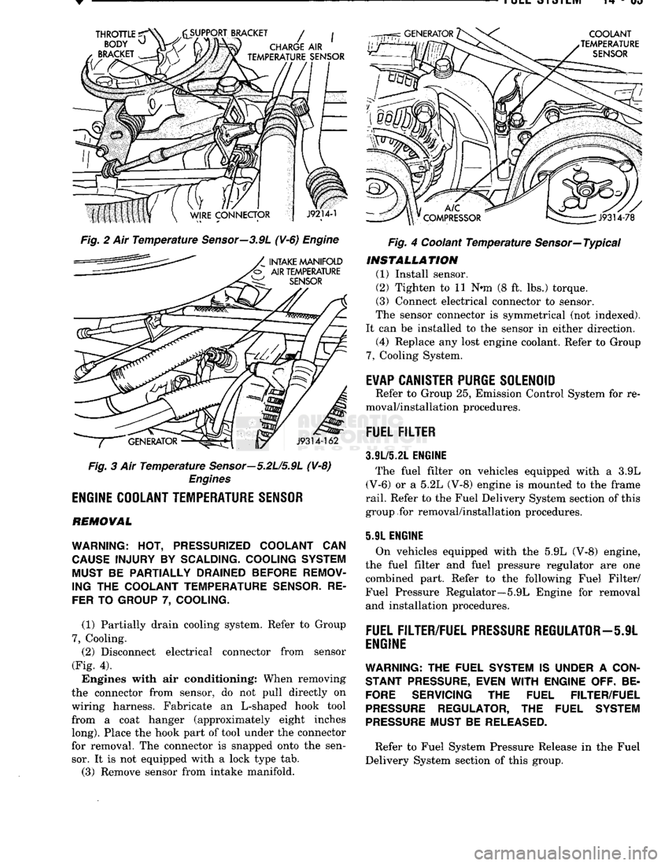
Fig. 2 Ait Temperature Sensor—3.9L (¥-6) Engine
Fig. 3 Air Temperature Sensor—5.2U5.9L (V-8)
Engines
ENGINE
COOLANT
TEMPERATURE
SENSOR
REMOVAL
WARNING:
HOT,
PRESSURIZED COOLANT
CAN
CAUSE
INJURY
BY
SCALDING- COOLING SYSTEM MUST
BE
PARTIALLY DRAINED BEFORE REMOV
ING
THE
COOLANT TEMPERATURE
SENSOR.
RE
FER
TO
GROUP
7,
COOLING.
(1) Partially drain cooling system. Refer to Group
7,
Cooling. (2) Disconnect electrical connector from sensor
(Fig. 4).
Engines with air conditioning: When removing
the connector from sensor, do not pull directly on
wiring harness. Fabricate an L-shaped hook tool from a coat hanger (approximately eight inches
long).
Place the hook part of tool under the connector
for removal. The connector is snapped onto the sen sor. It is not equipped with a lock type tab.
(3) Remove sensor from intake manifold. Fig. 4 Coolant Temperature Sensor—Typical
INSTALLATION
(1) Install sensor.
(2) Tighten to 11 Nnn (8 ft. lbs.) torque.
(3) Connect electrical connector to sensor.
The sensor connector is symmetrical (not indexed).
It can be installed to the sensor in either direction. (4) Replace any lost engine coolant. Refer to Group
7,
Cooling System.
E¥AP
CANISTER
PURGE
SOLENOID
Refer to Group 25, Emission Control System for re
moval/installation procedures.
FUEL
FILTER
3.9L/5.21.
ENGINE
The fuel filter on vehicles equipped with a 3.9L
(V-6) or a 5.2L (V-8) engine is mounted to the frame
rail.
Refer to the Fuel Delivery System section of this
group for removal/installation procedures.
5.91 ENGINE
On vehicles equipped with the 5.9L (V-8) engine,
the fuel filter and fuel pressure regulator are one combined part. Refer to the following Fuel Filter/
Fuel Pressure Regulator—5.9L Engine for removal and installation procedures.
FUEL
FILTER/FUEL
PRESSURE
REGULATOR—5JL
ENGINE
WARNING:
THE FUEL SYSTEM IS UNDER A
CON
STANT
PRESSURE,
EVEN
WITH
ENGINE OFF. BE
FORE
SERVICING THE FUEL FILTER/FUEL
PRESSURE
REGULATOR, THE FUEL SYSTEM
PRESSURE
MUST BE
RELEASED.
Refer to Fuel System Pressure Release in the Fuel
Delivery System section of this group.
Page 895 of 1502
DIESEL
FUEL
INJECTION—COMPONENT
DESCRIPTION/SYSTEM
OPERATION
NDEX
page
Air
Conditioning (A/C) Clutch
Relay-PCM
Output
. 81
Air
Conditioning (A/C)
Controls-PCM
Input
.... 77
Air
Intake Heater
Relays—PCM
Output
........ 81
Auto
Shut
Down
(ASD)
Relay-PCM
Output
.... 82
Automatic
Shut
Down
(ASD)
Sense-PCM
input
. 78
Battery
Voltage-PCM
Input
78
Brake
Switch—PCM
Input
....... 78
Charge
Air
Temperature
Sensor—PCM
Input
... 78
Engine
Speed
Sensor—PCM
Input
........... 78
Fuel
Drain Manifold
83
Fuel
Heater
83
Fuel
Injection
Pump
83
Fuel
Injectors
84
Fuel
Solenoid
84
Fuel/Water
Separator
Filter ................. 84
General
Information
76
Generator
Field-PCM
Output
. 81
High
Pressure
Fuel
Lines
85
Ignition
Sense—PCM
Input
78
KSB
Solenoid
....... 85
Malfunction Indicator
Lamp—PCM
Output
...... 82
Manual
Shut
Down
Lever
.................. 85
GENERAL
INFORMATION
The fuel system of the 5.9L (in-line six-cylinder)
turbo-diesel engine (Fig. 1) consists of the following components:
• Fuel tank
• Low and high pressure fuel supply lines
• Mechanical lift pump
• Fuel/water separator filter
• Fuel heater
• Fuel injection pump
• Fuel injectors • Fuel return lines For information regarding fuel requirements of the
5.9L turbo-diesel engine, refer to the Fuel Require
ments—Diesel Engines paragraph at the front of this group. Although various components, relays and switches
are operated by the powertrain control module (PCM), the diesel fuel injection system (Fig. 1) is not
directly regulated by the PCM. Refer to the proceed
ing Powertrain Control Module section for additional
information.
SYSTEM
DIAGNOSIS
The PCM tests many of its own input and output
circuits. If a diagnostic trouble code (DTC) is found in a major system, this information is stored in the
PCM memory. Refer to On-Board Diagnostics in the Diesel Fuel Injection—General Diagnosis section of
page
Mechanical
Lift
Pump
86
Overdrive
Indicator
Lamp—PCM
Output
....... 82
Overdrive
Solenoid-PCM
Output
............ 82
Overdrive/Override
Switch—PCM
Input
........ 79
Park/Neutral
Switch-PCM
Input
79
Power
Ground-PCM
Input
. 79
Powertrain Control Module
(PCM)
76
SCI
Receive-PCM
Input
. . 80
SCI
Transmit-PCM
Output
. . . 82
Sensor
Return-PCM
Input
................. 80
Signal
Ground-PCM
Input
. 80
Speed
Control-PCM
Input
80
Speed
Control-PCM
Output
82
System
Diagnosis
76
System
Operation
86
Tachometer-PCM
Output
82
Throttle
Position
Sensor
(TPS)-PCM
Input
80
Vehicle
Speed
Sensor-PCM
Input
80
Wait-To-Start
Lamp-PCM
Output
82
Water-ln-Fuel
Lamp-PCM
Output
83
Water-ln-Fuel
Sensor-PCM
input
80
this group for DTC information. The DRB II scan tool can be used to access the DTC messages stored in the PCM memory.
POWERTRAIN
CONTROL
MODULE
(PCM)
The powertrain control module (PCM) (Fig. 2) was
formerly referred to as the SBEC or engine control ler. The PCM is a pre-programmed, dual micropro
cessor digital computer. The PCM is located in the engine compartment be
hind the battery and under the left front fender (Fig.
2).
The PCM contains a voltage convertor, which con
verts battery voltage to a regulated 8.0 volts. This is used to power the engine speed sensor. The PCM also
provides a 5 volt supply for the throttle position sensor (TPS). The TPS is not used if equipped with a
manual transmission.
Various sensors, switches and relays provide the
inputs necessary for operation of the PCM.
The PCM Inputs are from:
9
Air conditioning control switch
• Automatic shut down (ASD) sense circuit
• Battery voltage
• Brake light switch • Charge air temperature sensor ® Coolant temperature sensor (Auto, trans, only)
• Engine speed sensor
• Ignition
• Overdrive/override switch
• Park/neutral switch (Auto, trans, only)
Page 898 of 1502
•
FUEL SYSTEM
14-79
OVERDRIVE/OVERRIDE SWITCH-PCM
INPUT
The overdrive/override switch is not used with
manual transmissions. On vehicles equipped with overdrive, the PCM reg
ulates the 3-4 overdrive upshift and downshift
through the overdrive solenoid. An override switch is located on the instrument panel. The overdrive/override switch is a momentary con
tact switch. The switch contacts are normally open. When the switch is activated, the PCM will receive a ground signal. The transmission will not enter over
drive when the operator presses the override switch.
The transmission downshifts if the operator presses
the override switch while in overdrive.
COOLANT TEMPERATURE SENSOR The coolant temperature sensor is not used with
manual transmissions.
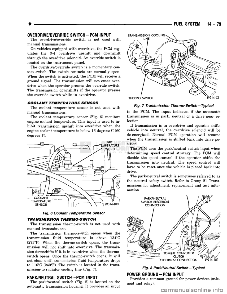
The coolant temperature sensor (Fig. 6) monitors
engine coolant temperature. This input is used to in
hibit transmission upshift into overdrive when the
engine coolant temperature is below 16 degrees C (60
degrees F).
Fig.
6 Coolant
Temperature
Sensor
TRANSMISSION THERMO-SWITCH The transmission thermo-switch is not used with
manual transmissions.
The transmission thermo-switch opens when the
transmission fluid temperature is above 134°C (273°F). When the thermo-switch opens, the trans
mission will not shift into overdrive. The transmis sion downshifts if it is in overdrive when the thermo-
switch opens. Once the thermo-switch opens, it will
not close until transmission fluid temperature drops
to 116°C (240°F). The switch is located in the trans mission-to-radiator cooling line (Fig. 7).
PARK/NEUTRAL SWITCH-PCM
INPUT
The park/neutral switch (Fig. 8) is located on the
automatic transmission housing. It provides an input
THERMO SWITCH
J9214-62
Fig.
7
Transmission
Thermo-Switch—Typical to the PCM. The input indicates if the automatic
transmission is in park, neutral or a drive gear se lection.
If transmission is in overdrive and operator shifts
vehicle into neutral, the overdrive solenoid will be de-energized. Normal PCM operation will resume
when the transmission is shifted back into drive po sition.
The PCM uses the park/neutral switch input when
determining speed control strategy. The PCM will
disable the speed control if the operator shifts the
transmission into neutral. The speed control will
have to be reset once the vehicle is placed back into drive.
The park/neutral switch is sometimes referred to as
the neutral safety switch. Refer to Group 21 Trans missions for adjustment, replacement and test infor
mation.
Fig.
8 Park/Neutral Switch—Typical
POWER
GROUND-PCM
INPUT
Provides a common ground for power devices (sole
noid and relay).