brake light DODGE TRUCK 1993 Service Manual PDF
[x] Cancel search | Manufacturer: DODGE, Model Year: 1993, Model line: TRUCK, Model: DODGE TRUCK 1993Pages: 1502, PDF Size: 80.97 MB
Page 572 of 1502

WIRING
DIAGRAMS
8W - 97
FUSE
#9
(20 AMP)
TURN SIGNAL
FLASHER
(MOUNTED
ON
RELAY
BANK)
(SEE
SH 82)
L19
18PK
A31
14BK/WT—(
TO
IGNITION
SWITCH
(SEE
SH 10)
TO REAR WHEEL
ANTI-LOCK
(RWAL) MODULE
(SEE
SH 31 ,33)
A15 16PK
A15
16PK 23 L5
14RD-
TO CHARGING
SYSTEM
(SEE
SH 3.5)
FUSE
#13
(20 AMP)
TO TACHOMETER
_T PROVISION
>
(SEE SH 48)
L19
18PK
HAZARD
WARNING
FLASHER
MOUNTED
ON
RELAY
BANK)
SEE
SH 82)
TO BRAKE SWITCH
SEE
SH 36,38)
L50
18WT TN
•L50
18WT/TN
•L50
18WT/TN•
GRAY
CL50
HAZARD
FLASHER
SWITCH CONNECTOR
(SEE
SH 87,88)
TO REAR WHEEL
<
ANTI-LOCK
i
(RWAL) MODULE
(SEE
SH 32.34)
L61
18LG
L61
18LG
11
»-L6G
18TN-
TO
REAR
LIGHTING
(SEE
SH 79)
TURN SIGNAL
SWITCH
(ON STEERING COLUMN)
L63
18DG/RD
L62 18BR/RD ,000/ 4
5 6
TO LEFT PRINTED CIRCUIT BOARD CONNECTOR
(SEE
SH 60)
21
22
-L61
18LG-5
LSI
18LG -£
L60
18TN—5
•L60
18TN—^
TO
FRONT
END
LIGHTING
(SEE
SH 43.45)
L60
18TN TO RIGHT
PRINTED CIRCUIT
BOARD
CONNECTOR
(SEE
SH 60)
BLACK
d938w-n
STOP/TURN
AND
HAZARD
FLASHER SYSTEMS
AD 56
Page 848 of 1502
•
FUEL
SYSTEM
14-29
MULTI-PORT
FUEL
INJECTION
(MPI)-COMPONENT DESCRIPTION/SYSTEM
OPERATION-EXCEPT DIESEL
INDEX
page
Air
Conditioning (A/C) Clutch
Relay-Pern
Output
. 35
Air
Conditioning (A/C)
Controls—PCM
Input
.... 31
Auto
Shut
Down
(ASD)
Relay-PCM
Output
. ... 36
Automatic
Shut
Down
(ASD)
Sense-PCM
Input
. 31
Battery
Voltage-PCM
Input
32
Brake
Switch-PCM
Input
32
Camshaft
Position
Sensor—PCM
Input
32
Charge
Air
Temperature
Sensor—PCM
Input
. . . 32
Crankshaft
Position
Sensor-PCM
Input
.......
32
Electric
Exhaust
Gas Recirculation Transducer
(EET)
Solenoid-PCM
Output
...
.......
36
Engine
Coolant Temperature
Sensor—PCM
Input
. 33
EVAP
Canister
Purge
Solenoid—PCM
Output
. . . 37
Fuel
Injectors-PCM Output
37
Fuel
Pressure
Regulator
41
Fuel
Rail
41
General
Information
.......................
29
Generator
Field-PCM
Output
36
Generator
Lamp-PCM
Output
36
Idle
Air
Control
(IAC)
Motor-PCM
Output
......
36
Ignition
Circuit
Sense—PCM
Input
33
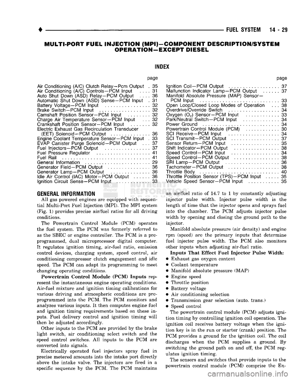
GENERAL
INFORMATION
All
gas
powered engines
are
equipped with sequen
tial Multi-Port Fuel Injection (MPI).
The MPI
system (Fig.
1)
provides precise air/fuel ratios
for all
driving
conditions. The Powertrain Control Module
(PCM)
operates
the fuel system.
The PCM was
formerly referred
to
as
the
SBEC
or
engine controller.
The PCM is a
pre
programmed, dual microprocessor digital computer. It regulates ignition timing, air-fuel ratio, emission
control devices, charging system, speed control,
air
conditioning compressor clutch engagement
and
idle speed.
The PCM can
adapt
its
programming
to
meet
changing operating conditions.
Powertrain Control Module (PCM) Inputs rep
resent
the
instantaneous engine operating conditions.
Air-fuel mixture
and
ignition timing calibrations
for
various driving
and
atmospheric conditions
are
pre
programmed into
the PCM. The PCM
monitors
and
analyzes various inputs.
It
then computes engine fuel
and ignition timing requirements based
on
these
in
puts.
Fuel delivery control
and
ignition timing will
then
be
adjusted accordingly. Other inputs
to the
PCM
are
provided
by the
brake
light switch,
air
conditioning select switch
and the
speed control switches.
All
inputs
to the PCM are
converted into signals. Electrically operated fuel injectors spray fuel
in
precise metered amounts into
the
intake port directly above
the
intake valve.
The
injectors
are
fired
in a
specific sequence
by the PCM. The PCM
maintains
page
Ignition
Coil-PCM
Output
37
Malfunction Indicator
Lamp—PCM
Output
37
Manifold
Absolute
Pressure
(MAP)
Sensor-
PCM
Input
33
Open
Loop/Closed
Loop
Modes
of
Operation
. . . 38
Overdrive/Override
Switch
34
Oxygen
(02)
Sensor—PCM
Input
33
Park/Neutral
Switch—PCM
Input
34
Power
Ground
34
Powertrain Control Module
(PCM)
30
SCI
Receive-PCM
Input
. 34
SCI
Transmit-PCM
Output
37
Sensor
Return
—PCM
Input
35
Shift Indicator-PCM Output
38
Speed
Control-PCM
Input
34
Speed
Control-PCM
Output
38
SRI
Lamp-PCM
Output
36
Tachometer—PCM
Output
38
Throttle
Body
40
Throttle
Position
Sensor
(TPS)-PCM
Input
35
Vehicle
Speed
Sensor-PCM
Input
35
an air/fuel ratio
of 14.7 to 1 by
constantly adjusting
injector pulse width. Injector pulse width
is the
length
of
time that
the
injector opens
and
sprays fuel into
the
chamber.
The PCM
adjusts injector pulse
width
by
opening
and
closing
the
ground path
to the
injector.
Manifold absolute pressure
(air
density)
and
engine
rpm (speed)
are the
primary inputs that determine
fuel injector pulse width.
The PCM
also monitors
other inputs when adjusting air-fuel ratio.
Inputs That Effect Fuel Injector Pulse Width:
• Exhaust
gas
oxygen content
• Coolant temperature
• Manifold absolute pressure (MAP)
• Engine speed
• Throttle position
• Battery voltage •
Air
conditioning selection
• Transmission gear selection (auto, trans.)
• Speed control The powertrain control module (PCM) adjusts igni
tion timing
by
controlling ignition coil operation.
The
ignition coil receives battery voltage when
the
igni
tion
key is in the run or
starter (crank) position.
The
PCM provides
a
ground
for the
ignition coil.
The
coil
discharges when
the PCM
supplies
a
ground.
By
switching
the
ground path
on and off, the PCM
reg
ulates ignition timing.
The sensors
and
switches that provide inputs
to the
powertrain control module
(PCM)
comprise
the En-
Page 851 of 1502

14
- 32
FUEL SYSTEM
•
BATTERY VOLTAGE—PCM
INPUT
The battery voltage input provides power
to the
powertrain control module (PCM).
It
also informs
the
PCM what voltage level
is
supplied
to the
ignition
coil
and
fuel injectors. If battery voltage
is low, the PCM
will increase injec
tor pulse width (period
of
time that
the
injector
is
ener
gized).
This
is
done
to
compensate
for the
reduced flow
through injector caused
by the
lowered voltage.
BRAKE
SWITCH-PCM
INPUT
When
the
brake light switch
is
activated,
the
pow
ertrain control module
(PCM)
receives
an
input indi
cating that
the
brakes
are
being applied. After
receiving this input,
the PCM
maintains idle speed
to
a
scheduled
rpm
through control
of the
idle
air
control
(IAC)
motor.
The
brake switch input
is
also
used
to
operate
the
speed control system.
CAMSHAFT POSITION SENSOR—PCM
INPUT
A sync signal
is
provide
by the
camshaft position sen
sor located
in the
ignition distributor
(Fig.
3).
The
sync
signal from this sensor works
in
conjunction with
the
crankshaft position sensor
to
provide
the
powertrain
control module
(PCM)
with inputs. This
is
done
to es
tablish
and
maintain correct injector firing order. Refer
to
Camshaft Position Sensor
in
Group
8D, Ig
nition System
for
more information.
Fig.
3
Camshaft Position
Sensor
CHARGE AIR TEMPERATURE SENSOR-PCM
INPUT
The intake manifold charge
air
temperature sensor
is installed
in the
intake manifold with
the
sensor
el
ement extending into
the air
stream
(Fig. 4). The
sensor provides
an
input voltage
to the
powertrain control module
(PCM)
indicating intake manifold
air
temperature.
The
input
is
used along with inputs from other sensors
to
determine injector pulse width. As
the
temperature
of the
air-fuel stream
in the
manifold varies,
the
sensor resistance changes. This
results
in a
different input voltage
to the PCM.
Fig.
4
Charge
Air
Temperature
Sensor—Typical
CRANKSHAFT POSITION SENSOR-PCM INPUT
This sensor
is a
hall effect device that detects
notches
in the
flywheel (manual transmission),
or
flexplate (automatic transmission). This sensor
is
used
to
indicate
to the
powertrain
control module
(PCM)
that
a
spark
and or
fuel injec
tion event
is to be
required.
The
output from this sensor,
in
conjunction with
the
camshaft position
sensor signal,
is
used
to
differentiate between fuel
in
jection
and
spark events.
It is
also used
to
synchro nize
the
fuel injectors with their respective cylinders. The sensor
is
bolted
to the
cylinder block near
the
rear
of the
right cylinder head
(Fig. 5).
Fig.
5
Crankshaft Position Sensor—Typical
Page 867 of 1502
CAV
WIRE
COLOR DESCRIPTION
CAV
WIRE
COLOR DESCRIPTION
1 DG/RD*
MAP SENSOR 37
BK/OR OVERDRIVE LAMP
2 TN/BK*
ENGINE COOLANT TEMPERATURE SENSOR 38 PK/BK INJECTOR DRIVE
#5
3 RD/WT DIRECT BATTERY 39 GY/RD IAC MOTOR
#4
4
BK/LB*
SENSOR RETURN 40 BR/WT
IAC MOTOR
#2
5 BK/WT SIGNAL GROUND 41
BK/DG* OXYGEN SENSOR SIGNAL
6 VT/WT
5-VOLT
OUTPUT
(MAP AND TPS)
42
7 OR
8-VOLT
OUTPUT (DISTRIBUTOR PICK-UP) 43
GY/LB*
TACHOMETER SIGNAL OUTPUT (VEHICLES W/TACHOMETER)
8 44 GY CAMSHAFT POSITION SENSE
9 DB
J2-IGNITION FEED 45
LG SCI RECIEVE
10 R/WT OVERDRIVE OVERRIDE
46 CCD
(-)
11 BK/TN POWER GROUND 47 WT/OR* SPEED SENSOR SIGNAL
12 BK/TN POWER GROUND 48 BR/RD* SPEED CONTROL
SET
SWITCH
13 LB/BR
INJECTOR DRIVER
#4
49
YL/RD* SPEED CONTROL ON/OFF SWITCH
14 YL/WT
INJECTOR DRIVER
#3
50 WT/LG* SPEED CONTROL RESUME SWITCH
15 TN INJECTOR DRIVER
#2
51 DB/YL*
AUTO SHUTDOWN
(ASD)
RELAY
-
RETURN
16
WT/DB*
INJECTOR DRIVER
#1
52 PK/BK
EVAP CANISTER PURGE SOLENOID
17 DB/TN INJECTOR DRIVER
#7
(V-8
ONLY) 53 LG/RD* SPEED CONTROL VENT SOLENOID
18 DB/GY
INJECTOR DRIVER
#8
(V-8
ONLY) 54
OR/BK* SHIFT INDICATOR LIGHT (MANUAL TRANSMISSION ONLY)
19 BK/GY*
IGNITION COIL DRIVER 54
OR/BK* CONVERTOR CLUTCH SOLENOID (AUTO TRANSMISSION)
20 DG
GENERATOR FIELD CONTROL 55
OR/WT OVERDRIVE SOLENOID (AUTO TRANSMISSION ONLY)
21 BK/RD
CHARGE TEMPERATURE SENSOR 56
GY/PK SRI LAMP
(5.9L HDC
ENGINE)
22
OR/DB*
THROTTLE POSITION SENSOR
(TPS)
57
DG/OR ASD SENSE
23 TN/WT
OXYGEN SENSOR SIGNAL
(5.9L HDC
ENGINE) 58 LG/BK
INJECTOR DRIVER
#6
24 GY/BK IGNITION (CAMSHAFT POSITION SENSOR) 59
VT/BK IAC MOTOR
#1
25 PK
,
SCI
TRANSMIT 60
YL/BK* IAC MOTOR
#3
26 CCD
(-:-)
WIRE COLOR CODES LB
LIGHT BLUE
VT VIOLET
27 BR
A/C SWITCH SENSE BK BLACK
LG LIGHT GREEN
WT
WHITE
28 VT A/C SELECT BR BROWN
OR ORANGE
YL YELLOW
29 WT/PK* BRAKE SWITCH
-
DB DARK BLUE PK
PINK *
WITH TRACER
30 BY/YL*
PARK/NEUTRAL SWITCH DG DARK GREEN
RD
RED
31 GY
GRAY TN TAN
32 BK/PK*
MALFUNCTION INDICATOR LAMP
33 TN/RD*
SPEED CONTROL VACUUM SOLENOID CONNECTOR
34 DB/OR* A/C CLUTCH RELAY TERMINAL
|(pcKX>coooop0ffoj'
oooooooooojj
35 GY/YL*
EGR SOLENOID SHOWN W'41
30
50«M#5l31
604
%\
oooooooooo ••ooooooooooj
36 J9314-171
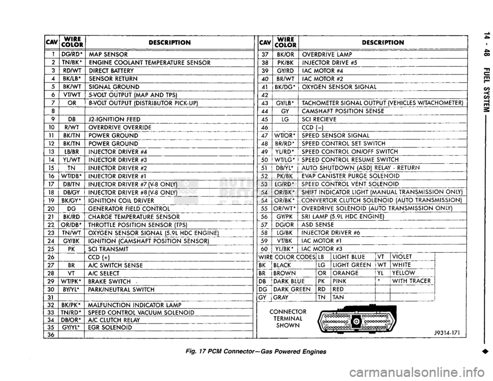
Fig.
17 PCM
Connector—Gas
Powered
Engines
Page 874 of 1502
•
FUEL
SYSTEM
14 - 55
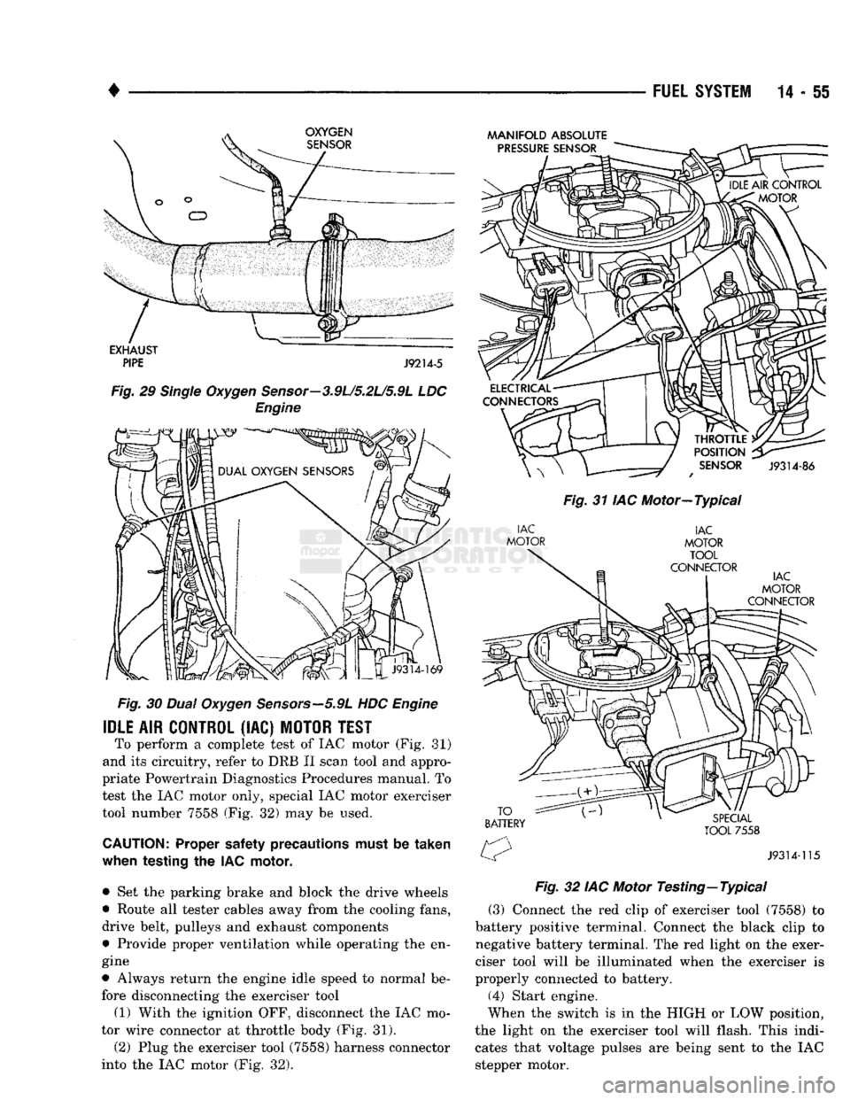
Fig.
30
Dual
Oxygen
Sensors—5.9L
HDC
Engine
IDLE
AIR
CONTROL
(IAC)
MOTOR
TEST
To perform a complete test of IAC motor (Fig. 81)
and its circuitry, refer to DRB II scan tool and appro
priate Powertrain Diagnostics Procedures manual. To
test the IAC motor only, special IAC motor exerciser tool number 7558 (Fig. 32) may be used.
CAUTION:
Proper safety precautions must be
taken
when
testing
the IAC
motor,
• Set the parking brake and block the drive wheels
• Route all tester cables away from the cooling fans,
drive belt, pulleys and exhaust components
• Provide proper ventilation while operating the en
gine
• Always return the engine idle speed to normal be
fore disconnecting the exerciser tool
(1) With the ignition OFF, disconnect the IAC mo
tor wire connector at throttle body (Fig. 31).
(2) Plug the exerciser tool (7558) harness connector
into the IAC motor (Fig. 32).
MANIFOLD
ABSOLUTE
Fig.
31 IAC Motor—Typical
Fig.
32 IAC Motor
Testing—
Typical
(3) Connect the red clip of exerciser tool (7558) to
battery positive terminal. Connect the black clip to
negative battery terminal. The red light on the exer
ciser tool will be illuminated when the exerciser is
properly connected to battery. (4) Start engine.
When the switch is in the HIGH or LOW position,
the light on the exerciser tool will flash. This indi cates that voltage pulses are being sent to the IAC
stepper motor.
Page 895 of 1502
DIESEL
FUEL
INJECTION—COMPONENT
DESCRIPTION/SYSTEM
OPERATION
NDEX
page
Air
Conditioning (A/C) Clutch
Relay-PCM
Output
. 81
Air
Conditioning (A/C)
Controls-PCM
Input
.... 77
Air
Intake Heater
Relays—PCM
Output
........ 81
Auto
Shut
Down
(ASD)
Relay-PCM
Output
.... 82
Automatic
Shut
Down
(ASD)
Sense-PCM
input
. 78
Battery
Voltage-PCM
Input
78
Brake
Switch—PCM
Input
....... 78
Charge
Air
Temperature
Sensor—PCM
Input
... 78
Engine
Speed
Sensor—PCM
Input
........... 78
Fuel
Drain Manifold
83
Fuel
Heater
83
Fuel
Injection
Pump
83
Fuel
Injectors
84
Fuel
Solenoid
84
Fuel/Water
Separator
Filter ................. 84
General
Information
76
Generator
Field-PCM
Output
. 81
High
Pressure
Fuel
Lines
85
Ignition
Sense—PCM
Input
78
KSB
Solenoid
....... 85
Malfunction Indicator
Lamp—PCM
Output
...... 82
Manual
Shut
Down
Lever
.................. 85
GENERAL
INFORMATION
The fuel system of the 5.9L (in-line six-cylinder)
turbo-diesel engine (Fig. 1) consists of the following components:
• Fuel tank
• Low and high pressure fuel supply lines
• Mechanical lift pump
• Fuel/water separator filter
• Fuel heater
• Fuel injection pump
• Fuel injectors • Fuel return lines For information regarding fuel requirements of the
5.9L turbo-diesel engine, refer to the Fuel Require
ments—Diesel Engines paragraph at the front of this group. Although various components, relays and switches
are operated by the powertrain control module (PCM), the diesel fuel injection system (Fig. 1) is not
directly regulated by the PCM. Refer to the proceed
ing Powertrain Control Module section for additional
information.
SYSTEM
DIAGNOSIS
The PCM tests many of its own input and output
circuits. If a diagnostic trouble code (DTC) is found in a major system, this information is stored in the
PCM memory. Refer to On-Board Diagnostics in the Diesel Fuel Injection—General Diagnosis section of
page
Mechanical
Lift
Pump
86
Overdrive
Indicator
Lamp—PCM
Output
....... 82
Overdrive
Solenoid-PCM
Output
............ 82
Overdrive/Override
Switch—PCM
Input
........ 79
Park/Neutral
Switch-PCM
Input
79
Power
Ground-PCM
Input
. 79
Powertrain Control Module
(PCM)
76
SCI
Receive-PCM
Input
. . 80
SCI
Transmit-PCM
Output
. . . 82
Sensor
Return-PCM
Input
................. 80
Signal
Ground-PCM
Input
. 80
Speed
Control-PCM
Input
80
Speed
Control-PCM
Output
82
System
Diagnosis
76
System
Operation
86
Tachometer-PCM
Output
82
Throttle
Position
Sensor
(TPS)-PCM
Input
80
Vehicle
Speed
Sensor-PCM
Input
80
Wait-To-Start
Lamp-PCM
Output
82
Water-ln-Fuel
Lamp-PCM
Output
83
Water-ln-Fuel
Sensor-PCM
input
80
this group for DTC information. The DRB II scan tool can be used to access the DTC messages stored in the PCM memory.
POWERTRAIN
CONTROL
MODULE
(PCM)
The powertrain control module (PCM) (Fig. 2) was
formerly referred to as the SBEC or engine control ler. The PCM is a pre-programmed, dual micropro
cessor digital computer. The PCM is located in the engine compartment be
hind the battery and under the left front fender (Fig.
2).
The PCM contains a voltage convertor, which con
verts battery voltage to a regulated 8.0 volts. This is used to power the engine speed sensor. The PCM also
provides a 5 volt supply for the throttle position sensor (TPS). The TPS is not used if equipped with a
manual transmission.
Various sensors, switches and relays provide the
inputs necessary for operation of the PCM.
The PCM Inputs are from:
9
Air conditioning control switch
• Automatic shut down (ASD) sense circuit
• Battery voltage
• Brake light switch • Charge air temperature sensor ® Coolant temperature sensor (Auto, trans, only)
• Engine speed sensor
• Ignition
• Overdrive/override switch
• Park/neutral switch (Auto, trans, only)
Page 901 of 1502
14 - 82
FUEL 'SYSTEM
—. — ~—— — «
INTAKE HEATER CYCLE CHART
Intake
featperafwre
Preheat
Cycle
Time
Ignition
l£ey ON
Engine
Not
Running
Pestheat
Cycle
Ignition
Key ON
Snglne Running
Above
15
°C
(59
°F)
0 Seconds
No
-8°C(18°F)to
15°C (59
°F)
10
Seconds
Yes
-17°C(1
°F)
-9
°C(]6°F)
15
Seconds
Yes
«2d°C(-15°F)
to-18°C(0
°F) 17.5
Seconds
Yes
Below-26
°C (-15
*F)
20 Seconds
Yes
J9114-239
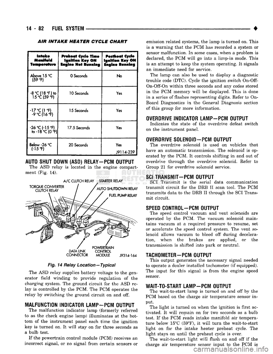
AUTO SHUT DOWN (ASD) RELAY-PCM OUTPUT
The ASD relay is located in the engine compart
ment (Fig. 14).
TORQUE CONVERTER
CLUTCH RELAY A/C CLUTCH RELAY STARTER RELAY
AUTO SHUTDOWN RELAY FUEL PUMP RELAY DATA LINK
CONNECTOR
POWERTRAIN
CONTROL MODULE
J9314-164
Fig.
14 Relay Location—Typical The ASD relay supplies battery voltage to the gen
erator field winding to provide regulation of the
charging system. The ground circuit for the ASD re
lay is controlled by the PCM. The PCM operates the
relay by switching the ground circuit on and off.
MALFUNCTION INDICATOR LAMP-PCM OUTPUT
The malfunction indicator lamp (formerly referred
to as the check engine lamp) illuminates at the bot
tom of the instrument panel each time the ignition
key is turned on. It will stay on for three seconds as
a bulb test. If the powertrain control module (PCM) receives an
incorrect signal, or no signal from certain sensors or emission related systems, the lamp is turned on. This
is a warning that the PCM has recorded a system or
sensor malfunction. In some cases, when a problem is
declared, the PCM will go into a limp-in mode. This is an attempt to keep the system operating. It signals
an immediate need for service.
The lamp can also be used to display a diagnostic
trouble code (DTC). Cycle the ignition switch
On-Off-
On-Off-On within three seconds and any codes stored
in the PCM memory will be displayed. This is done
in a series of flashes representing digits. Refer to On-
Board Diagnostics in the General Diagnosis section
of this group for more information.
OVERDRIVE
INDICATOR LAMP-PCM OUTPUT
Indicates the state of the overdrive defeat switch
on the instrument panel.
OVERDRIVE
S0LEN0ID-PCM OUTPUT
The overdrive solenoid is used on vehicles that
have an automatic transmission. The solenoid is op erated by the PCM. It controls shifting in and out of
overdrive through the overdrive solenoid. Refer to Group 21 for overdrive solenoid service.
SCI
TRANSMIT—PCM OUTPUT
SCI Transmit is the serial data communication
transmit circuit for the DRB II scan tool. The PCM
transmits data to the DRB II through the SCI Trans
mit circuit.
SPEED
C0NTR0L-PCM OUTPUT
The speed control vacuum and vent solenoids are
operated by the PCM. The vacuum solenoid main
tains vacuum at a required pressure to resume, set or accelerate the speed control system. The vent so
lenoid allows vacuum to bleed off during decelera
tion, when the brakes are applied, or the
transmission is shifted into park or neutral.
TACHOMETER-PCM
OUTPUT
This output generates the necessary signal needed
to operate a dealer installed tachometer (if equipped).
The input for this signal is from the engine speed sensor.
WAIT-TO-START LAMP-PCM OUTPUT
The wait-to-start lamp is turned on and off by the
PCM based on the charge air temperature sensor in
put. The light is turned on when the ignition is first ac
tivated. It will remain on for two seconds as a bulb
test. If the PCM reads intake manifold air tempera
ture below 15°C (59°F), it will turn the wait-to-start light on for the intake heater preheat cycle. The
light stays on until the preheat cycle is over. The wait-to-start light will flash on and off if the
charge air temperature sensor input to the PCM is
Page 909 of 1502

14
- 90
FUEL SYSTEM
Fig.
10 Air
Filter
Element—Diesel (17) Be sure that the turbocharger output hose is
connected to the charge air cooler (intercooler) inlet
tube.
Verify that the charge air cooler output hose is
connected to the cooler and the intake manifold (Fig.
11).
(18) Be sure that the vacuum pump-to-brake
booster hose is connected and not damaged. (19) Be sure that the accessory drive belt is not
damaged or slipping.
AIR
IN
FUEL SYSTEM
Air will enter the fuel system whenever fuel supply
lines,
separator filters, injection pump, high pressure
lines or injectors are removed or disconnected. Air
trapped in the fuel system can result in hard start
ing, a rough running engine, engine misfire, low
power, excessive smoke and fuel knock. After service is performed, air must be bled from the system before
starting the engine. •
Fig.
11
Charge
Air
Cooler
(Intercooler) Inspect the fuel system from the lift pump to the
injectors for loose connections. Leaking fuel is an in
dicator of loose connections or defective seals. Air can also enter the fuel system between the fuel tank and
the lift pump. Inspect the fuel tank and fuel lines for damage that might allow air into the system.
AIR INTAKE HEATER PREHEAT/POST-HEAT CYCLE
The PCM provides a ground path for the air intake
heater relays. The ground path is provided if intake
manifold temperature is below 16°C (60°F) when the
ignition key is in the ON position. When the ground is provided, the intake heaters are energized to start
the preheat cycle.
The preheat cycle can be tested with a voltmeter or
test light. If the intake manifold temperature is above 16°C (60°F), the wait-to-start light will not
come on and the air intake heaters will not be ener gized.
CAUTION:
Do not
energize
the air
intake
heater
re
lays
more than once
per 15
minutes.
If the
relays
are cycled,
the key
turned
off and
then
turned
back
on,
the
engine could
be
damaged. Wait
15
minutes before turning
the key
back
to the ON
position.
(1) With the engine not running and ambient air
temperature below 16°C (60°F), turn the ignition key
to the ON position.
(2) The wait-to-start light will come on and the air
intake heater relays should click on signaling the
start of the preheat cycle.
Page 918 of 1502
CAV
WIRE
COLOR DESCRIPTION
CAV
WIRE
COLOR DESCRIPTION
1 WT/BK
WATER-IN-FUEL SENSOR 37 OVERDRIVE LAMP SIGNAL
2 TN/BK
COOLANT SENSOR (AUTOMATIC TRANSMISSION ONLY) 38
3 RD BATTERY
39
4
BK/LB*
SENSOR RETURN 40
5 BK/WT
SIGNAL GROUND 41
6 VT/WT*
5 VOLT SUPPLY 42
7 TN/YL 8 VOLT INPUT 43 GR/LB TACHOMETER
8 44
9 DB
IGNITION SENSE 45 LG DATA LINK RECIEVE
10 RD/WT*
OVERDRIVE OVERRIDE 46
11 BK/TN POWER GROUND
47 WT/OR* VEHICLE SENSOR
12 BK/TN
POWER GROUND 48 BR/RD* SPEED CONTROL COAST/SET SWITCH
13 49 YL/RD* SPEED CONTROL ON/OFF SWITCH
14 50 WT/LG* SPEED CONTROL RESUME/ACCEL SWITCH
15 OR/BK* HEATER
#2
RELAY 51 DB/YL ASD RELAY
16 YL/BK HEATER #1 RELAY 52
17 53 LG/RD* SPEED CONTROL VENT SOLENOID
18 54 BK/PK* WATER-IN-FUEL LAMP
19 55 OR/LG* OVERDRIVE SOLENOID
20 DG GENERATOR FIELD 56 DG/WT WAIT-TO-START LAMP
21 BK/RD
CHARGE (INTAKE) AIR TEMPERATURE SENSOR 57 DG/OR ASD SENSE
22
OR/DB*
THROTTLE POSITION SENSOR 58
23 59
24 GY/BK
REFERENCE PICKUP 60
25 PK
DATA LINK TRANSMIT WIRE COLOR CODES LB
LIGHT BLUE VT VIOLET
26 BK BLACK LG LIGHT GREEN WT
WHITE
27 BR
A/C CLUTCH REQUEST BR BROWN OR ORANGE
YL YELLOW
28 LG/RD THERMO SWITCH DB DARK BLUE PK PINK *
WITH TRACER
29 WT/PK* BRAKE SWITCH DG DARK GREEN
RD RED
30 BR/YL*
PARK/NEUTRAL SWITCH GY GRAY TN TAN
31 ruin
32 BK/PK*
MALFUNCTION INDICATOR LAMP
n
33 TN/RD*
SPEED CONTROL VACUUM SOLENOID CONNECTOR
J//000OOOOOOO
1 1
HI
173456789
10 J/^"*\
Hi
oooooooooo (1 Oj]
VlX
21
22
23
24
25
26
27
28
29
30
\V~V//
oooooooooo
\
II
12 13
14 15
16 17 18
19 20
\
34 DB/OR
WIDE OPEN THROTTLE (A/C) TERMINAL
J//000OOOOOOO
1 1
HI
173456789
10 J/^"*\
Hi
oooooooooo (1 Oj]
VlX
21
22
23
24
25
26
27
28
29
30
\V~V//
oooooooooo)}
31
32 33 34 35 36 37 38 39 40
1JU
35 SHOWN \\\
41 42 43 44 45 46 47 48 49
SO
1
^m^^
|
oooooooooo
1
1
oooooooooo
J//
36
Li
J9314-185
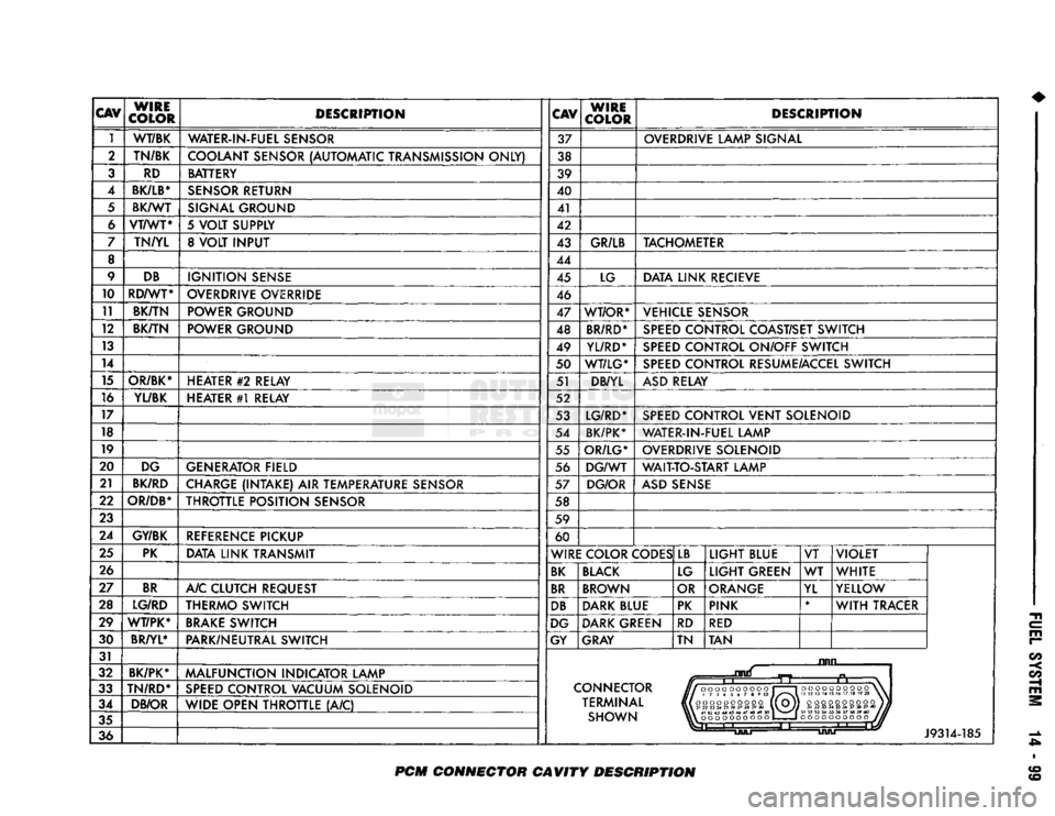
PCM
CONNECTOR CAVITY DESCRIPTION
Page 969 of 1502
19
- 8
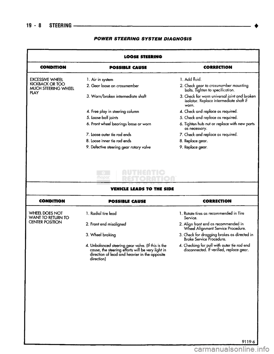
STEERING
POWER
STEERING
SYSTEM
DIAGNOSIS
LOOSE
STEERING
CONDITION
POSSIBLE
CAUSE
CORRECTION
EXCESSIVE
WHEEL
KICKBACK
OR
TOO
MUCH
STEERING
WHEEL
PLAY
1.
Air in system
2.
Gear
loose
on
crossmember
3.
Worn/broken intermediate shaft
4.
Free
play in steering column
5.
Loose
ball
joints
6. Front wheel bearings
loose
or worn
7.
Loose
outer tie rod
ends
8.
Loose
inner
tie
rod
ends
9.
Defective steering gear
rotary
valve
1.
Add
fluid.
2.
Check
gear
to
crossmember
mounting bolts. Tighten
to
specification,
3.
Check
for worn universal
joint
ond
broken isolator.
Replace
intermediate shaft
if
worn.
4.
Check
and replace
as
required. 5.
Check
and replace
as
required.
6.
Tighten hub nut or replace
with
new parts
as
necessary.
7.
Check
and replace
as
required.
8.
Replace
gear.
9.
Replace
gear.
VEHICLE
LEADS
TO THE
SIDE
CONDITION
POSSIBLE
CAUSE
CORRECTION
WHEEL
DOES
NOT
WANT
TO
RETURN
TO
CENTER
POSITION
1. Radial
tire
lead
2. Front
end
misaligned
3.
Wheel braking
4.
Unbalanced
steering
gear
valve.
(If this is the
cause,
the steering
efforts
will
be very
light
in
direction
of
lead and heavier in the opposite
direction)
1.
Rotate
tires
as
recommended in Tire
Service.
2. Align
front
end
as
recommended
in
Wheel
Alignment
Service
Procedure.
3.
Check
for
dragging
brakes
as
directed
in
Brake
Service
Procedure.
4.
Checking
for
pull
with
outer
tie
rod end
disconnected.
If verified, replace gear.
9119-6