steering wheel DODGE VIPER 2008 ZB II / 2.G Owners Manual
[x] Cancel search | Manufacturer: DODGE, Model Year: 2008, Model line: VIPER, Model: DODGE VIPER 2008 ZB II / 2.GPages: 303, PDF Size: 2.65 MB
Page 41 of 303
Driver and Passenger Supplemental Restraint
System (SRS) - Airbag
This vehicle is equipped with airbags for the driver and
passenger as a supplement to the seat belt restraint
systems. The driver airbag is mounted in the steering
wheel. The passenger airbag is mounted underneath a
cover in the passenger's side of the instrument panel. The
words SRS/AIRBAG is embossed on the airbag covers.
NOTE:The airbags are certified to the Federal regula-
tions that allow less forceful deployment. The passenger
airbag is certified to the Federal regulations that define
Occupant Classification (Refer to ªHow The Airbag Sys-
tem Worksº in this section).
The airbags have a multi stage inflator design. This may
allow the airbag to have different rates of inflation that
are based on collision severity and occupant size.
WARNING!
²Do not put anything on or around the airbag covers or
attempt to open them manually. You may damage the
airbags and you could be injured because the airbags are
no longer functional. These protective covers for the
airbag cushions are designed to open only when the
airbags are inflating.
²Do not drill, cut, or tamper with the knee bolster in any
way.
²Do not mount any accessories to the knee bolster such as
alarm lights, stereos, citizens band radios, etc.
²Relying on the airbags alone could lead to more severe
injuries in a collision. The airbags work with your seat
belt to restrain you properly. In some collisions, the
airbags won't deploy at all. Always wear your seat belts
even though you have airbags.
²Being too close to the steering wheel or instrument panel
during airbag deployment could cause serious injury.
Airbags need room to inflate. Sit back, extending your
arms comfortably to reach the steering wheel or instru-
ment panel.
40 THINGS TO KNOW BEFORE STARTING YOUR VEHICLE
Page 44 of 303
²Steering Wheel and Column
²Instrument Panel
²Seat Track Position Sensors
²Interconnecting Wiring
²Seat Belt Reminder Light
²Knee Impact Bolsters
²Front Acceleration Sensors
²Passenger Seat Occupant Classification System (OCS)
þOccupant Classification Module (OCM)
þPassenger Airbag Disabled (PAD) Indicator Light
þFlex Mat
þInterconnecting Wiring
þSeat Track Position Sensors
How The Airbag System Works
²
TheOccupant Restraint Controller (ORC)determines
if a frontal collision is severe enough to require the
airbags to inflate. The airbag inflators are designed to
provide different rates of inflation. Based on the level
of collision severity, the ORC determines the proper
rate of inflation. The ORC may modify the rate of
passenger airbag inflation or prevent passenger airbag
deployment based on input from the Occupant Clas-
sification System (OCS). The ORC will not detect roll
over or rear impacts. Furthermore, the airbags are not
on and will not inflate if the key is in the OFF/LOCK
position, in the ACC position, or not in the ignition.
The ORC also monitors the readiness of the electronic
parts of the system whenever the ignition switch is in
the ON/RUN position. These include all of the items
listed under ªAirbag System Componentsº except the
steering wheel and column and the knee bolsters.
THINGS TO KNOW BEFORE STARTING YOUR VEHICLE 43
2
Page 45 of 303
The ORC turns on the Airbag warning light
and Passenger Airbag Disable (PAD) indica-
tor light for 6 to 8 seconds as a self-check
when the ignition is first turned on. After the
self-check, the Airbag warning light will turn off and
the PAD indicator light will function normally (Refer to
ªPassenger Airbag Disable (PAD) Indicator Lightº in
this section). If the ORC detects a malfunction in any
part of the system, it turns on the Airbag warning light
either momentarily or continuously. A single chime will
sound if the light comes on again after initial start up.
WARNING!
Ignoring the Airbag Warning Light in your instrument
panel could mean you won't have the airbags to protect
you in a collision. If the light does not come on, stays
on after you start the vehicle, or if it comes on as you
drive, have the airbag system checked right away.
²TheDriver Airbag/Inflator Unitis mounted in the
steering wheel. ThePassenger Airbag/Inflator Unitis
mounted underneath a cover in the passenger side of
the instrument panel. When the ORC detects a colli-
sion requiring the airbags, it signals the inflator units.
A large quantity of non-toxic gas is generated to inflate
the airbags. Different airbag inflation rates may be
possible based on collision severity and occupant size.
The steering wheel hub trim cover and the upper right
side of the instrument panel separate and then fold out
of the way, as the bags inflate to their full size. The
bags inflate fully in about 50±70 milliseconds. This is
about half of the time it takes to blink your eyes. The
bags then deflate quickly while helping to restrain the
driver and passenger. The airbag gas is vented toward
the instrument panel through vent holes in the airbag
material. In this way, the airbags do not interfere with
your control of the vehicle.
44 THINGS TO KNOW BEFORE STARTING YOUR VEHICLE
Page 90 of 303
Adding Washer Fluid
The windshield washer fluid reservoir is located in the
front of the engine compartment on the passenger side of
the vehicle. Be sure to check the fluid level in the
reservoir at regular intervals. Fill the reservoir with
windshield washer solvent (not radiator antifreeze) and
operate the system for a few seconds to flush out the
residual water.
WARNING!
Commercially available windshield washer solvents
are flammable. They could ignite and burn you. Care
must be exercised when filling or working around
the washer solution.
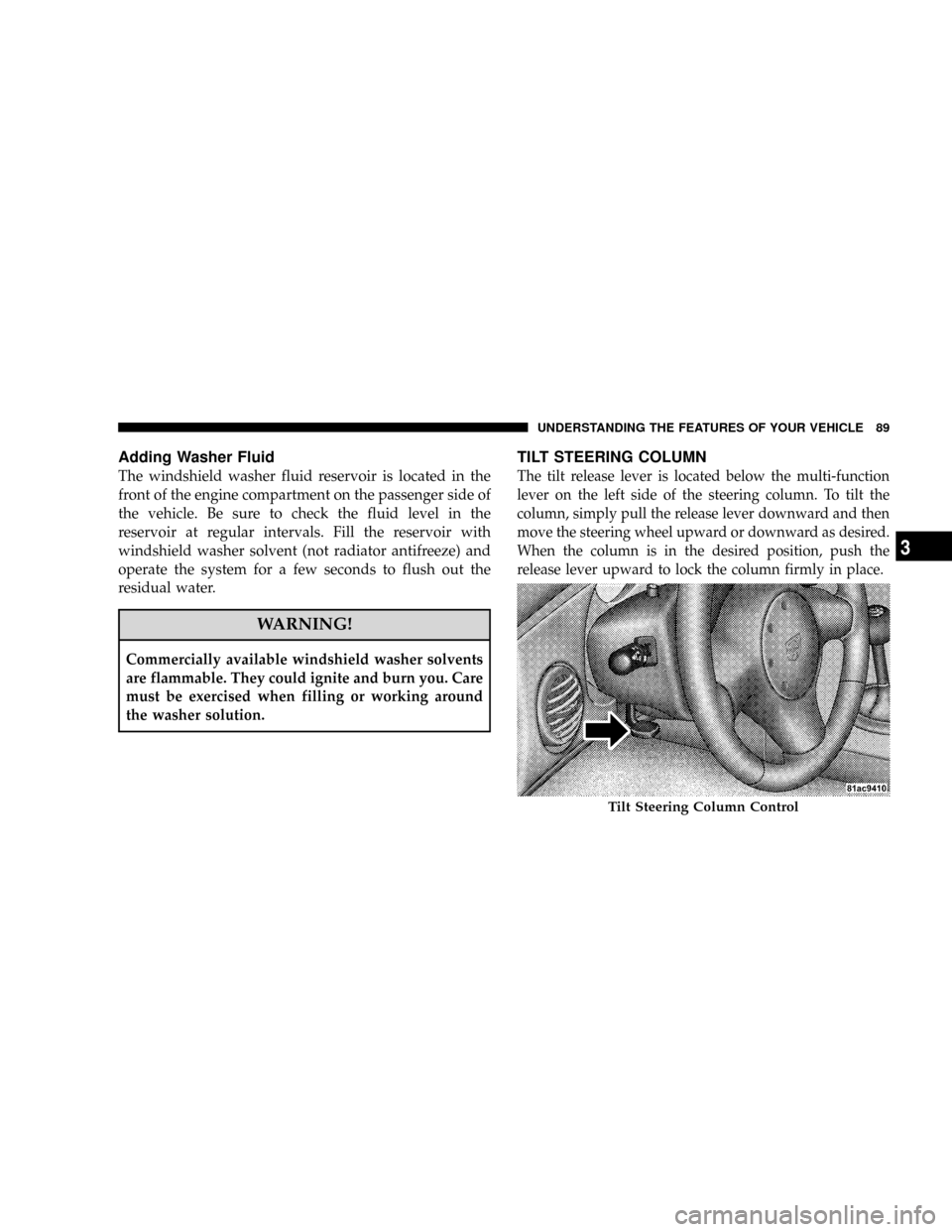
TILT STEERING COLUMN
The tilt release lever is located below the multi-function
lever on the left side of the steering column. To tilt the
column, simply pull the release lever downward and then
move the steering wheel upward or downward as desired.
When the column is in the desired position, push the
release lever upward to lock the column firmly in place.
Tilt Steering Column Control
UNDERSTANDING THE FEATURES OF YOUR VEHICLE 89
3
Page 108 of 303
you understand and save you concern about these ªap-
parentº malfunctions, you must understand a point or
two about the transmission and reception of radio sig-
nals.
Two Types of Signals
There are two basic types of radio signals: AM or
Amplitude Modulation, in which the transmitted sound
causes the amplitude, or height, of the radio waves to
vary; and FM or Frequency Modulation, in which the
frequency of the wave is varied to carry the sound.
Electrical Disturbances
Radio waves may pick up electrical disturbances during
transmission. They mainly affect the wave amplitude,
and thus remain a part of the AM reception. They
interfere very little with the frequency variations that
carry the FM signal.
AM Reception
AM sound is based on wave amplitude, so AM reception
can be disrupted by such things as lightning, power lines
and neon signs.
FM Reception
Because FM transmission is based on frequency varia-
tions, interference that consists of amplitude variations
can be filtered out, leaving the reception relatively clear,
which is the major feature of FM radio.
NOTE:The radio, steering wheel radio controls (if
equipped), and 6±Disc CD/DVD changer (if equipped)
will remain active for up to 10 minutes after the ignition
switch has been turned OFF. Opening a vehicle front
door will cancel this feature.
UNDERSTANDING YOUR INSTRUMENT PANEL 107
4
Page 149 of 303
POWER STEERING
The standard power steering system will give you good
vehicle response and increased ease of maneuverability
in tight spaces. The system will provide mechanical
steering capability if power assist is lost.
If for some reason the power assist is interrupted, it will
still be possible to steer your vehicle. Under these condi-
tions, you will observe a substantial increase in steering
effort, especially at very low vehicle speeds and during
parking maneuvers.
NOTE:Increased noise levels at the end of the steering
wheel travel are considered normal and do not indicate
that there is a problem with the power steering system.
Upon initial start-up in cold weather, the power steering
pump may make noise for a short amount of time. This is
due to the cold, thick fluid in the steering system. This
noise should be considered normal, and it does not in any
way damage the steering system.WARNING!
Continued operation with reduced power steering
assist could pose a safety risk to yourself and others.
Service should be obtained as soon as possible.
CAUTION!
Prolonged operation of the steering system at the end
of the steering wheel travel will increase the steering
fluid temperature and it should be avoided when
possible. Damage to the power steering pump may
occur.
148 STARTING AND OPERATING
Page 164 of 303
WARNING!
²Do not use a tire, wheel size or rating other than
that specified for your vehicle. Some combinations
of unapproved tires and wheels may change sus-
pension dimensions and performance characteris-
tics, resulting in changes to steering, handling, and
braking of your vehicle. This can cause unpredict-
able handling and stress to steering and suspen-
sion components. You could lose control and have
an accident resulting in serious injury or death.
Use only the tire and wheel sizes with load ratings
approved for your vehicle.
²Never use a tire with a smaller load index or
capacity, other than what was originally equipped
on your vehicle. Using a tire with a smaller load
index could result in tire overloading and failure.
You could lose control and have an accident.
²Failure to equip your vehicle with tires having
adequate speed capability can result in sudden tire
failure and loss of vehicle control.
CAUTION!
Replacing original tires with tires of a different size
may result in false speedometer and odometer
readings.
Alignment And Balance
Poor suspension alignment may result in:
²Fast tire wear.
²Uneven tire wear, such as feathering and one-sided
wear.
²Vehicle pull to right or left.
Tires may also cause the vehicle to pull to the left or right.
Alignment will not correct this condition. See your dealer
for proper diagnosis.
STARTING AND OPERATING 163
5
Page 165 of 303
Improper alignment will not cause vehicle vibration.
Vibration may be a result of tire and wheel out-of-
balance. Proper balancing will reduce vibration and
avoid tire cupping and spotty wear.
TIRE CHAINS
Due to limited clearance, tire chains are not recom-
mended.
CAUTION!
Damage to the vehicle may result if tire chains are
used.
SNOW TIRES
There are no snow tires that are compatible with the
wheels on this vehicle.
TIRE STORAGE
Tire storage is addressed in the Michelin Limited Tire
Warranty Booklet.
Specific recommendations on guidelines for long term
tire storage for this vehicle should be requested of the
Michelin Tire Corporation 1-800-433-6838.
TIRE ROTATION RECOMMENDATIONS
Tires on the front and rear axles of vehicles operate at
different loads and perform different steering, driving,
and braking functions. For these reasons, they wear at
unequal rates, and tend to develop irregular wear pat-
terns.
These effects can be reduced by timely rotation of tires.
The benefits of rotation are especially worthwhile with
164 STARTING AND OPERATING
Page 177 of 303
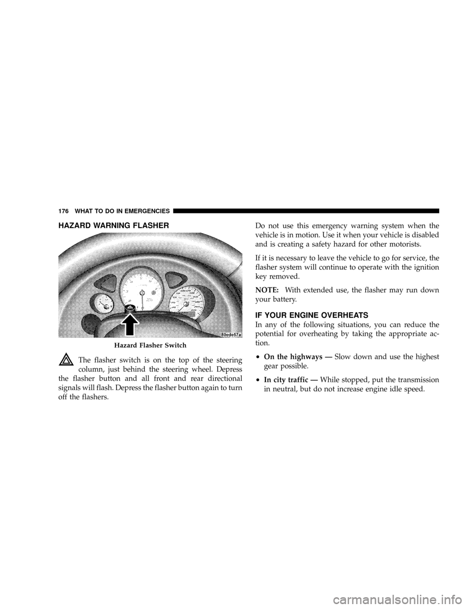
HAZARD WARNING FLASHER
The flasher switch is on the top of the steering
column, just behind the steering wheel. Depress
the flasher button and all front and rear directional
signals will flash. Depress the flasher button again to turn
off the flashers.Do not use this emergency warning system when the
vehicle is in motion. Use it when your vehicle is disabled
and is creating a safety hazard for other motorists.
If it is necessary to leave the vehicle to go for service, the
flasher system will continue to operate with the ignition
key removed.
NOTE:With extended use, the flasher may run down
your battery.
IF YOUR ENGINE OVERHEATS
In any of the following situations, you can reduce the
potential for overheating by taking the appropriate ac-
tion.
²On the highways ÐSlow down and use the highest
gear possible.
²In city traffic ÐWhile stopped, put the transmission
in neutral, but do not increase engine idle speed.
Hazard Flasher Switch
176 WHAT TO DO IN EMERGENCIES
Page 184 of 303
²Turn the Mode Select knob to the Sealant/Air Mode.
²Connect the Power Plug (5) to a different power
outlet in your vehicle or another vehicle, if available.
Make sure the engine is running before turning on
the TIREFIT kit.
²The Sealant Bottle (1) may be empty due to previous
use. Call for assistance.
(D) After Injecting TIREFIT Sealant:
1. Allow the air pump to inflate the tire to the pressure
indicated on the tire pressure label on the driver-side
latch pillar. Check the pressure in the tire by looking at
the Pressure Gauge (2).
²If the tire inflates to at least 26 psi (1.8 bar) within 15
minutes, proceed to Step 2 of this procedure.
²If tire fails to inflate to 26 psi (1.8 bar) within 15
minutes, perform the procedure steps described
under ª(G) Distributing TIREFIT Sealant to Better
Enable Tire Inflation.º
²Press the Air Pump Power Button (3) to
turn off the TIREFIT kit.
2. Remove the Speed Limit sticker from the top of the
Sealant Bottle (1) and place the sticker on the steering
wheel.
3. Disconnect the TIREFIT kit from the valve stem and
place it in the vehicle.
(E) Securing TIREFIT Sealant in the Tire
Drive the vehicle for approximately 5 miles (8 km) to
ensure distribution of the TIREFIT Sealant within the tire.
WHAT TO DO IN EMERGENCIES 183
6