light DODGE VIPER 2010 ZB II / 2.G Owner's Manual
[x] Cancel search | Manufacturer: DODGE, Model Year: 2010, Model line: VIPER, Model: DODGE VIPER 2010 ZB II / 2.GPages: 80, PDF Size: 8.08 MB
Page 27 of 80
Daylight Savings
• Use a ball point pen or similar object to press the "H" (hour) or "M" (Minute) button toaccess the clock setup screen.
• Press ENTER to select Clock Setup.
• Rotate the Selector knob to highlight Daylight Savings and press ENTER.
• Rotate the Selector knob to highlight St andard or Daylight Savings and press ENTER.
• Turn the Selector knob to highlight DONE and press ENTER or wait 5 seconds.
Changing Time Zone
• Use a ball point pen or similar object to press the "H" (hour) or "M" (Minute) button to access the clock setup screen.
• Press ENTER to select Clock Setup.
• Rotate the Selector knob to highlight Time Zone and press ENTER.
• Rotate the Selector knob to highlight the desired Time Zone and press ENTER.
• Turn the Selector knob to highlight DONE and press ENTER or wait 5 seconds.
Store Radio Presets
• Find the station to store by either pressing the seek up/down button, the tune up/down button, or by t ouching the SCAN button.
• Turn the Selector knob to highlight SET and press ENTER. SET 1 appears on the display.
• Then select button (1–5).
• You may add a second station to each pushb utton by repeating the above procedure
with this exception: After highlighting SET, press ENTER twice. SET 2 appears on the
display, then select button (1–5).
Navigation
Navigation Radio – RB1 Only
• Your navigation system receives GPS signals from up to 8 satellites to display the position and direction of your vehicle.
• Map and database information is supplied through a DVD-ROM and vehicle sensors enable the system to display the present vehicle position even in locations where GPS
may be blocked.
• The DVD-ROM disc must be inserted into the radio before accessing the Navigation mode.
NOTE: Many features of this radio are speed dependent. For your own safety, some of
the programmable options will be grayed out and unavailable while the vehicle is in
motion. Pull over at a safe location to complete your task.
New Destination
• Press the NAV button to access the NAV Main Menu.
• Using the Selector knob, highlight Destination to program a destination, press ENTER, then select one of the 8 ways to input a destination.
25
ELECTRONICS
Page 28 of 80
Program Destination by Street Address
• Press the NAV button to access the NAV Main Menu.
• Select/highlight Destination from the Main Menu screen and press ENTER.
• Select/highlight Street Address from the Find Destination by screen and press ENTER.
• Select/highlight Street Name from the Find Address screen and press ENTER.
NOTE: City, State and Province can be also be changed in the Find Address screen.
• The Input Street Name screen appears. Use the Selector knob to spell out the street
name. Select/highlight each letter and press ENTER.
• Select/highlight Street List and press ENTER to continue. The Select Street Name screen appears. Select/highlight the c orrect street and press ENTER.
• The Input Address screen appears. Us e the Selector knob to input the address
number. When finished, select/highlight Done and press ENTER.
• Lastly, the Confirm Destination screen appe ars, showing the address of the selected
destination. If it is correct, select/highlight OK and press ENTER. The system will
calculate a route to that destination.
Address Book
• Press the NAV button, use the Selector knob to highlight Destination and press ENTER.
• Select/highlight one of the eight choices to input a destination and press ENTER.
• Enter the address information following the screen prompts.
• Once a destination has been entered, select/highlight Options from the Confirm Destination screen and press ENTER.
• Select/Highlight Save in Address Book and press ENTER.
• The Input Name screen appears. Use the Select Encoder to spell out the name you
would like to see in the Address Book.
• Select/highlight Done when finished and press ENTER.
• The Input Phone Number screen appears. Use the Select Encoder to input the phone
number of the address. When the number is complete, or if you do not know the
phone number, select/highlight Save and press ENTER.
• The name, address and phone number are now stored in the address book. The Confirm Destination screen will reappear showing the saved information.
Map
• Press the NAV button and select/highlight Map and press ENTER.
• The Map screen will appear showing your current location.
Adjusting Navigation Volume
• The navigation volume can be adjusted during a voice command by using the radioPower/Volume control knob.
• To repeat a voice command select the voice icon on the Map or Arrow guidance.
ELECTRONICS
26
Page 32 of 80
Front Splitter
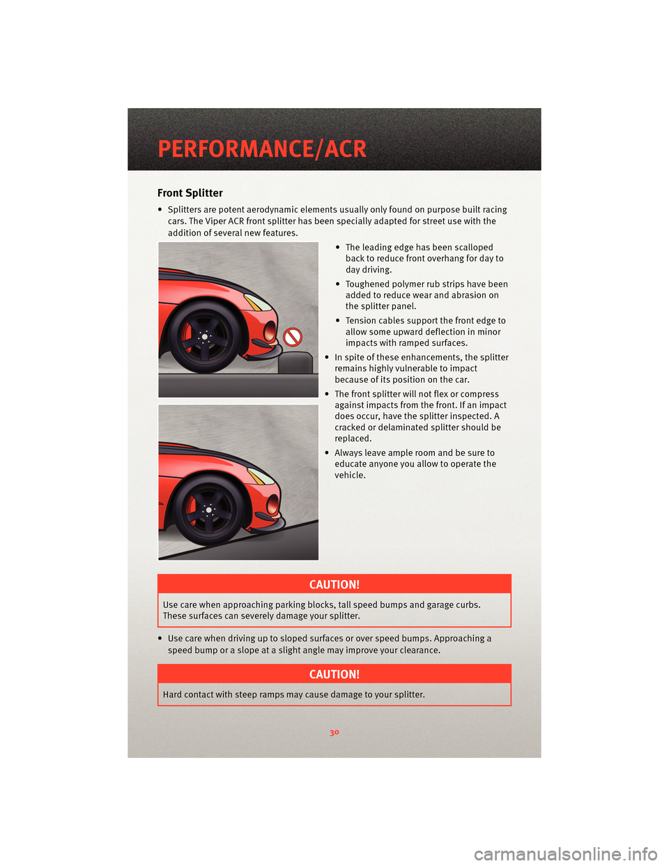
• Splitters are potent aerodynamic elements usually only found on purpose built racing
cars. The Viper ACR front splitter has been specially adapted for street use with the
addition of several new features.
• The leading edge has been scallopedback to reduce front overhang for day to
day driving.
• Toughened polymer rub strips have been added to reduce wea r and abrasion on
the splitter panel.
• Tension cables support the front edge to allow some upward deflection in minor
impacts with ramped surfaces.
• In spite of these enhancements, the splitter remains highly vulnerable to impact
because of its position on the car.
• The front splitter will not flex or compress against impacts from the front. If an impact
does occur, have the splitter inspected. A
cracked or delaminated splitter should be
replaced.
• Always leave ample room and be sure to educate anyone you allow to operate the
vehicle.
CAUTION!
Use care when approaching parking bloc ks, tall speed bumps and garage curbs.
These surfaces can severely damage your splitter.
• Use care when driving up to sloped surfaces or over speed bumps. Approaching a speed bump or a slope at a slight angle may improve your clearance.
CAUTION!
Hard contact with steep ramps may cause damage to your splitter.
PERFORMANCE/ACR
30
Page 36 of 80
• The rear wing on the non two-tone ACR is molded completely with unidirectionalcarbon fiber and painted in body color. Some patterned or linear conditions may be
visible in the p ainted carbon fiber surfaces. This i s also a normal result of the carbon
fiber process.
TWO PIECE BRAKE ROTORS
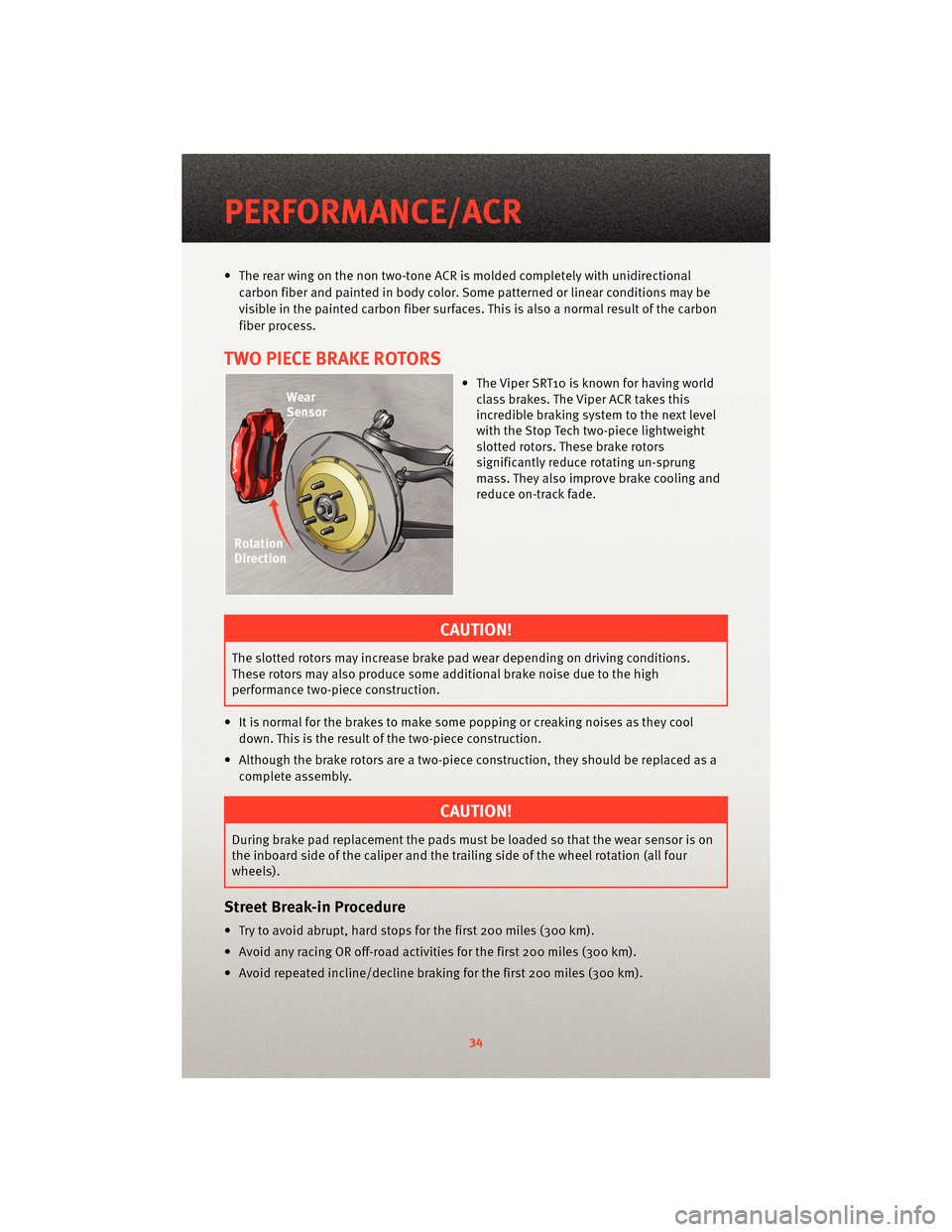
• The Viper SRT10 is known for having world class brakes . The Viper ACR takes this
incredible braking system to the next level
with the Stop Tech two-piece lightweight
slotted rotors. These brake rotors
significantly reduce rotating un-sprung
mass. They also improve brake cooling and
reduce on-track fade.
CAUTION!
The slotted rotors may increase brake pad wear depending on driving conditions.
These rotors may also produce some additional brake noise due to the high
performance two-piece construction.
• It is normal for the brakes to make some popping or creaking noises as they cool down. This is the result of the two-piece construction.
• Although the brake rotors are a two-piece construction, they should be replaced as a complete assembly.
CAUTION!
During brake pad replacement the pads must be loaded so that the wear sensor is on
the inboard side of the caliper and the trailing side of the wheel rotation (all four
wheels).
Street Break-in Procedure
• Try to avoid abrupt, hard stops for the first 200 miles (300 km).
• Avoid any racing OR off-road activities for the first 200 miles (300 km).
• Avoid repeated incline/decline braking for the first 200 miles (300 km).
PERFORMANCE/ACR
34
Page 37 of 80
Alternate Break in Procedure
CAUTION!
Chrysler does not endorse speeding on public roads; therefore, if a safe area cannot
be used for break-in, you must perform the street break-in procedure. Regardless of
completing the “street brea k-in procedure,” this alternative break-in procedure is
recommended before any track use of the vehicle.
• In the event that the street break-in procedure can’t be performed before the pads and
rotors are thermally stressed, use the following procedure:
• Read through the procedure and find a suitab le, safe and legal area to perform the
necessary stops.
• BEFORE starting the break-in procedure, drive with gentle braking. Do not use
brakes aggressively until performing brake-in procedure.
• Make a series of 10 stops from 60 to 5-10 MPH. At the end of each stop, immediately accelerate to 60 again for the next stop. Run all stops continuously in
one cycle.
NOTE: A moderate braking effort is needed to properly break in the rotors and pads. A
stopping force of approxim ately 0.8G’s, just short of ABS intervention, is the level of
pedal effort you are trying to attain.
• During the 60 to 5-10 MPH series of stops, the exact speed is not critical. Accelerateto approximately 60 and begin the brak ing cycle. As you approach 5-10 MPH, it is
not necessary to watch the speedometer. Keep your eyes on the road and
approximate your speed at the end of each cycle.
CAUTION!
Do not come to a complete stop! This will imprint pad material onto the rotor, causing
a vibration during future use.
• Watch for the following:
• On the 8th or 9th stop, there should be a distinct smell from the brakes. Smoke may be evident during earlier stops as well.
• Also on the 8th or 9th stop, some friction materials will experience “green fade”. This is a slight fading of the brakes. The fade will
stabilize, but not completely go away until the brakes have cooled.
• After the break-in cycle is finished there will be a light gray film on the rotor face. The gray film is pad material starting to transfer onto the
rotor face.
35
PERFORMANCE/ACR
Page 45 of 80
HARD CORE PACKAGE
• This option is for the Hard Core track enthusiast who is looking for maximum weight
savings.
• The Hard Core Package eliminates the Audio System (including the radio, amplifier,
door speakers and subwoofer). Also delet ed are the under hood silencer pad, the
trunk carpet and the tire inflator. The door speakers are replaced by carbon fiber
panels. The radio is replaced by a lightweight cover that can be configured to mount
the included Lap Timer.
CAUTION!
The tire inflator has been removed from the Hard Core package. There are no
measures for flat tire repair included with this vehicle. It is recommended that drivers
always bring a mobile phone in case of a flat tire.
• The removal of the trunk carpeting reduces sound insulation. It is normal to hear more road and drivetrain noise.
• The Lap Timer kit includes the Timer, Beacon Receiver, a power cord, download kit and the Beacon Transmitter.
• The Lap Timer displays lap times on a large illuminated digital display. It continuously updates the fastest laps and acquires a running data log of all times during the track
event. This data can be do wnloaded for analysis via a USB connection. Refer to your
AiM lap timer manual for instructions.
• The cables to the beacon receiver and power jack include extra long lengths. This is to provide the ability to custom fit the timer and beacon receiver depending on the track
and/or driver preference.
• Note on Lap Timer: For lap timer software updates and technical support contact www.aimsports.com/software/index.html.
43
PERFORMANCE/ACR
Page 49 of 80
24-HOUR TOWING ASSISTANCE - U.S. ONLY
• Dial toll-free 1-800-521-2779 or 1-800-363-4869 for Canadian residents.
• Provide your name, vehicle identification number and license plate number.
• Provide your location, including telephone number, from which you are calling.
• Briefly describe the nature of the problem and answer a few simple questions.
• You will be given the name of the service provider and an estimated time of arrival. Ifyou feel you are in an “unsafe situation”, please let us know. With your consent, we
will contact local police or safety authorities.
INSTRUMENT CLUSTER WARNING LIGHTS
- Tire Pressure Monitoring System (TPMS) Light
• Each tire, including the spare (if provided), should be checked monthly, when coldand inflated to the inflation pressure recommended by the vehicle manufacturer on
the vehicle placard or tire inflation pressure label. (If your vehicle has tires of a
different size than the size indicated on the v ehicle placard or tire inflation pressure
label, you should determine the proper tire inflation pressure for those tires.)
• As an added safety feature, your vehicle has been equipped with a Tire Pressure Monitoring System (TPMS) that illuminates a low tire pressure telltale when one or
more of your tires is significantly under-inflat ed. Accordingly, when the low tire
pressure telltale illuminates, you should stop and check your tires as soon as
possible, and inflate them to the proper pressure. Driving on a significantly
under-inflated tire causes the tire to overheat and can lead to tire failure.
Under-inflation also reduces fuel efficiency and tire tread life, and may affect the
vehicle’s handling and stopping ability.
• Please note that the TPMS is not a subs titute for proper tire maintenance, and it is the
driver’s responsibility to maintain correct tire pressure, even if under-inflation has not
reached the level to trigger illumination of the TPMS low tire pressure telltale.
• Your vehicle has also been equipped with a TPMS malfunction indicator to indicate
when the system is not operating properly. The TPMS malfunction indicator is
combined with the low tire pressure telltale. When the system detects a malfunction,
the telltale will flash for approximately one minute and then remain continuously
illuminated. This sequence will continue upon subsequent vehicle start-ups as long as
the malfunction exists.
• When the malfunction indicator is illuminated, the system may not be able to detect or signal low tire pressure as intended. TPMS malfunctions may occur for a variety of
reasons, including the installation of replacement or alternate tires or wheels on the
vehicle that prevent the TPMS from functioning properly. Always check the TPMS
malfunction telltale after replacing one or more tires or wheels on your vehicle, to
ensure that the replacement or alternate tires and wheels allow the TPMS to continue
to function properly.
47
WHAT TO DO IN EMERGENCIES
Page 50 of 80
CAUTION!
The TPMS has been optimized for the original equipment tires and wheels. TPMS
pressures and warning have been established for the tire size equipped on your
vehicle. Undesirable system operation or sensor damage may result when using
replacement equipment that is not of the same size, type, and/or style. Aftermarket
wheels can cause sensor damage. Do not use tire sealant from a can, or balance
beads if your vehicle is equipped with a TPMS, as damage to the sensors may result.
- Engine Temperature Warning Light
• This light warns of an overheated engine condition.
• If the light turns on and a warning chime sounds while driving, safely pull over andstop the vehicle. If the A/C system is on, t urn it off. Also, shiftthe transmission into
NEUTRAL and idle the vehicle. If the temperat ure reading does not return to normal,
turn the engine off immediately.
• We recommend that you do not operate the vehicle or engine damage will occur. Have the vehicle serviced immediately.
WARNING!
A hot engine cooling system is dangero us. You or others could be badly burned by
steam or boiling coolant. You may want to call an authorized service center for service
if your vehicle overheats.
- Brake Warning Light
• The Brake Warning light illuminates when there is either a system malfunction or the parking brake is applied. If the light is on and the parking brake is not applied, it
indicates a possible brake hydraulic malfunction, brake booster problem or an
Anti-Lock Brake System problem.
• We recommend you drive to the nearest service center and have the vehicle serviced immediately.
WARNING!
Driving a vehicle with the red brake light on is dangerous. Part of the brake system
may have failed. It will take longer to stop the vehicle. You could have an accident.
Have the vehicle checked immediately.
WHAT TO DO IN EMERGENCIES
48
Page 51 of 80
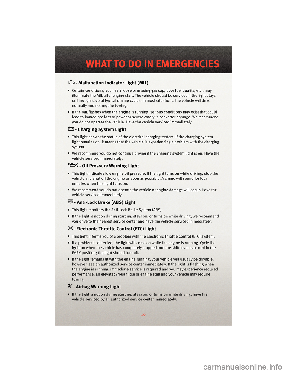
- Malfunction Indicator Light (MIL)
• Certain conditions, such as a loose or missing gas cap,poor fuel quality, etc., may
illuminate the MIL after engine start. The vehicle should be serviced if the light stays
on through several typical driving cycles. In most situations, the vehicle will drive
normally and not require towing.
• If the MIL flashes when the engine is running, serious conditions may exist that could lead to immediate loss of power or severe catalytic converter damage. We recommend
you do not operate the vehicle. Hav e the vehicle serviced immediately.
- Charging System Light
• This light shows the status of the electrical ch arging system. If the charging system
light remains on, it means that the vehicle is experiencing a problem with the charging
system.
• We recommend you do not continue driving if the charging system light is on. Have the vehicle serviced immediately.
- Oil Pressure Warning Light
• This light indicates low engine oil pressure. If the light turns on while driving, stop thevehicle and shut off the engine as soon as possible. A chime will sound for four
minutes when this light turns on.
• We recommend you do not operate the vehicle or engine damage will occur. Have the vehicle serviced immediately.
- Anti-Lock Brake (ABS) Light
• This light monitors the Anti-Lock Brake System (ABS).
• If the light is not on during starting, stays on, or turns on while driving, we recommendyou drive to the nearest service center and have the vehicle serviced immediately.
- Electronic Throttle Control (ETC) Light
• This light informs you of a problem with the Electronic Throttle Control (ETC) system.
• If a problem is detected, the light will come on while the engine is running. Cycle theignition when the vehicle has completely stopped and the shift lever is placed in the
PARK position; the light should turn off.
• If the light remains lit with the engine running, your vehicle will usually be drivable; however, see an authorized service center immediately. If the light is flashing when
the engine is running, immediate service is required and you may experience reduced
performance, an elevated/rough idle or en gine stall and your vehicle may require
towing.
- Airbag Warning Light
• If the light is not on during starting, stays on, or turns on while driving, have the vehicle serviced by an authorized service center immediately.
49
WHAT TO DO IN EMERGENCIES
Page 61 of 80
OPENING THE HOOD
• Reach into the lower right grille opening and pull the primary hood latch forward.
• Raise the front of the hood slightly and push the safety catch handle to the right. Thesafety catch handle is located under the front edge of the hood.
• Assist props will ra ise the hood to a normal usage p osition. If greater access is
required, the hood may be pushed up at the front, raising the hood beyond the initial
opening height.
• To close, lower the hood until it is open ap proximately 6 in (15 cm) and then drop it.
This should secure both latches.
WARNING!
Be sure the hood is fully latched before driving your vehicle. If the hood is not fully
latched, it could open when the vehicle is in motion and block your vision. Failure to
follow this warning could result in serious injury or death.
59
MAINTAINING YOUR VEHICLE