lock DODGE VIPER 2015 VX / 3.G User Guide
[x] Cancel search | Manufacturer: DODGE, Model Year: 2015, Model line: VIPER, Model: DODGE VIPER 2015 VX / 3.GPages: 148, PDF Size: 21.7 MB
Page 5 of 148
VEHICLES SOLD IN CANADA
With respect to any vehicles sold in Canada, the name FCA US LLC shall be deemed to be
deleted and the name FCA Canada Inc. used in substitution (excluding legal lines).
WARNING!
•Pedalsthatcannotmovefreelycancauselossofvehiclecontrolandincreasethe
risk of serious personal injury.
•Alwaysmakesurethatobjectscannotfallintothedriverfootwellwhilethevehicle
is moving. Objects can become trapped under the brake pedal and accelerator
pedal causing a loss of vehicle control.
•Failuretoproperlyfollowfloormatinstallationormountingcancauseinterference
with the brake pedal and accelerator pedal operation causing loss of control of the
vehicle.
•Never leave children alone in a vehicle, or with access to an unlocked vehicle. Allowing
children to be in a vehicle unattended is dangerous for a number of reasons. A child or
others could be seriously or fatally injured. Children should be warned not to touch the
parking brake, brake pedal or the shift lever/transmission gear selector.
•Do not leave the key fob in or near the vehicle, or in a location accessible to children,
and do not leave the ignition of a vehicle equipped with Keyless Enter-N-Go™ in the
ACC or ON/RUN mode. A child could operate power windows, other controls, or move
the vehicle.
•Neverusethe“PARK”positionasasubstitutefortheparkingbrake.Alwaysapply
the parking brake fully when parked to guard against vehicle movement and
possible injury or damage.
•RefertoyourOwner'sManualontheDVDforfurtherdetails.
USE OF AFTERMARKET PRODUCTS (ELECTRONICS)
The use of aftermarket devices including cell phones, MP3 players, GPS systems, or
chargers may affect the performance of on-board wireless features including Keyless
Enter-N-Go™ and Remote Start range. If you are experiencing difficulties with any of your
wireless features, try disconnecting your aftermarket devices to see if the situation
improves. If your symptoms persist, please see an authorized dealer.
CHRYSLER, DODGE, JEEP, RAM, MOPAR and Uconnect are registered trademarks of
FCA US LLC.
COPYRIGHT ©2015 FCA US LLC
INTRODUCTION/WELCOME
3
Page 6 of 148
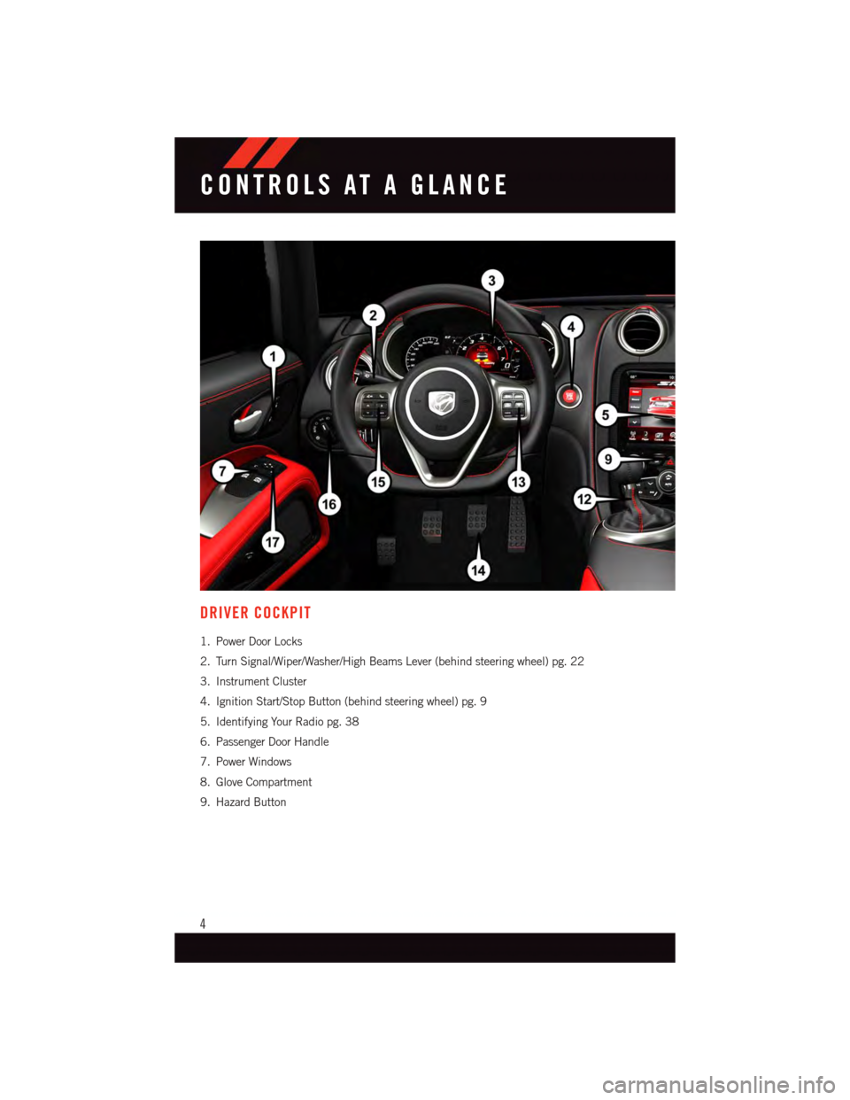
DRIVER COCKPIT
1. Power Door Locks
2. Turn Signal/Wiper/Washer/High Beams Lever (behind steering wheel) pg. 22
3. Instrument Cluster
4. Ignition Start/Stop Button (behind steering wheel) pg. 9
5. Identifying Your Radio pg. 38
6. Passenger Door Handle
7. Power Windows
8. Glove Compartment
9. Hazard Button
CONTROLS AT A GLANCE
4
Page 10 of 148
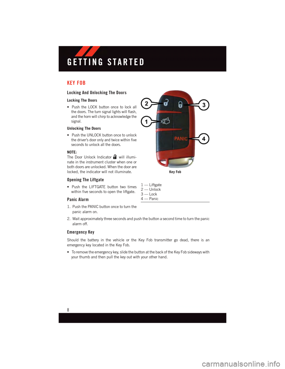
KEY FOB
Locking And Unlocking The Doors
Locking The Doors
•Push the LOCK button once to lock all
the doors. The turn signal lights will flash,
and the horn will chirp to acknowledge the
signal.
Unlocking The Doors
•Push the UNLOCK button once to unlock
the driver’s door only and twice within five
seconds to unlock all the doors.
NOTE:
The Door Unlock Indicatorwill illumi-
nate in the instrument cluster when one or
both doors are unlocked. When the door are
locked, the indicator will not illuminate.
Opening The Liftgate
•PushtheLIFTGATEbuttontwotimes
within five seconds to open the liftgate.
Panic Alarm
1. Push the PANIC button once to turn the
panic alarm on.
2. Wait approximately three seconds and push the button a second time to turn the panic
alarm off.
Emergency Key
Should the battery in the vehicle or the Key Fob transmitter go dead, there is an
emergency key located in the Key Fob.
•Toremovetheemergencykey,slidethebuttonatthebackoftheKeyFobsidewayswith
your thumb and then pull the key out with your other hand.
Key Fob
1—Liftgate2—Unlock3—Lock4—Panic
GETTING STARTED
8
Page 11 of 148
WARNING!
•Alwaysapplytheparkingbrakefullywhenparkedtoguardagainstvehiclemove-
ment and possible injury or damage.
•Never leave children alone in a vehicle, or with access to an unlocked vehicle. Allowing
children to be in a vehicle unattended is dangerous for a number of reasons. A child or
others could be seriously or fatally injured. Children should be warned not to touch the
parking brake, brake pedal or the transmission gear selector.
•Do not leave the Key Fob in or near the vehicle, or in a location accessible to children,
and do not leave the ignition of a vehicle equipped with Keyless Enter-N-Go™ in the
ACC or ON/RUN mode. A child could operate power windows, other controls, or move
the vehicle.
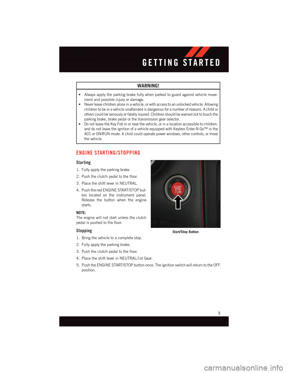
ENGINE STARTING/STOPPING
Starting
1. Fully apply the parking brake.
2. Push the clutch pedal to the floor.
3. Place the shift lever in NEUTRAL.
4. Push the red ENGINE START/STOP but-
ton located on the instrument panel.
Release the button when the engine
starts.
NOTE:
The engine will not start unless the clutch
pedal is pushed to the floor.
Stopping
1. Bring the vehicle to a complete stop.
2. Fully apply the parking brake.
3. Push the clutch pedal to the floor.
4. Place the shift lever in NEUTRAL/1st Gear.
5. Push the ENGINE START/STOP button once. The ignition switch will return to the OFF
position.
Start/Stop Button
GETTING STARTED
9
Page 12 of 148
VEHICLE SECURITY ALARM
The Vehicle Security Alarm monitors the vehicle doors for unauthorized entry and the
Keyless Enter-N-Go™ START/STOP button for unauthorized operation. While the Vehicle
Security Alarm is armed, interior switches for door locks and decklid release are disabled.
If something triggers the alarm, the Vehicle Security Alarm will provide the following
audible and visible signals: the horn will pulse, the park lamps and/or turn signals will
flash, and the Vehicle Security Light in the instrument cluster will flash.
To Arm:
Follow these steps to arm the Vehicle Security Alarm:
•PushLOCKontheinteriorpowerdoorlockswitchwiththedriverand/orpassengerdoor
open.
•PushtheLOCKbuttonontheRemoteKeylessEntry(RKE)transmitter.
•TheVehicleSecurityLightintheinstrumentclusterwillflashfor16seconds.This
shows that the Vehicle Security Alarm is arming. During this period, if a door is opened,
the ignition is cycled to ON/RUN, or the power door locks are unlocked in any manner,
the Vehicle Security Alarm will automatically disarm.
NOTE:
•Duringthe16-secondarmingperiod,ifadoorisopenedortheignitioniscycledto
ON/RUN, the Vehicle Security Alarm will automatically disarm.
•Oncearmed,theVehicleSecurityAlarmdisablestheunlockswitchonthedriverdoor
trim panel and passenger door trim panel.
•UsingthekeytoopentheliftgatewhiletheVehicleSecurityAlarmisarmedwillnot
trigger the theft alarm.
To Disarm:
The Vehicle Security Alarm can be disarmed using any of the following methods:
•PushtheUNLOCKbuttonontheRemoteKeylessEntry(RKE)transmitter.
•CyclethevehicleignitionsystemoutoftheOFFposition.
GETTING STARTED
10
Page 16 of 148
Supplemental Side Air Bags
•ThisvehicleisequippedwithSupplementalDoor-IntegratedSideAirBagInflatable
Curtains (SABICs). The SABICs are located in the door trim below the side windows.
The trim covering the SABICs is labeled SRS AIRBAG.
•TheSABICsmayhelpreducetheriskofpartialorcompleteejectionofvehicle
occupants through side windows in certain side impact events.
•SABICsaredesignedtoactivateincertainsideimpacts.TheOccupantRestraint
Controller (“ORC”) determines whether the deployment of the SABIC in a particular
impact event is appropriate, based on the severity and type of collision. Vehicle damage
by itself is not a good indicator of whether or not SABICs should have deployed.
WARNING!
•RelyingontheSABICsalonecouldleadtomoresevereinjuriesinacollision.The
SABICs work with your seat belt to restrain you properly. In some collisions, SABICs
won’t deploy at all. Always wear your seat belt even though you have SABICs.
•SABICsneedroomtoinflate.Donotleanagainstthedoororwindow.Situprightin
the center of the seat.
•BeingtooclosetotheSABICsduringdeploymentcouldcauseyoutobeseverely
injured or killed.
•YourvehicleisequippedwithleftandrightSupplementalDoor-IntegratedSideAir
Bag Inflatable Curtains (SABICs). Do not stack luggage or other cargo up high
enough to block the deployment of the SABICs. The door trim below the side
windows where the SABIC and its deployment path are located, should remain free
from any obstructions.
CHILD RESTRAINTS
Children 12 years or younger should ride properly buckled up in a rear seat, if available.
According to crash statistics, children are safer when properly restrained in the rear seats
rather than in the front.
Every state in the United States and all Canadian provinces require that small children
ride in proper restraint systems. This is the law, and you can be prosecuted for ignoring it.
NOTE:
•Foradditionalinformation,refertowww.Seatcheck.orgorcall1-866-SEATCHECK.
•CanadianresidentsshouldrefertoTransportCanada’swebsiteforadditionalinforma-
tion: http://www.tc.gc.ca/eng/motorvehiclesafety/safedrivers-childsafety-index-53.htm
GETTING STARTED
14
Page 17 of 148
Installing the Child Restraint Using the Vehicle Seat Belts
•ThefrontpassengerseatingpositionisequippedwithaSwitchableAutomaticLocking
Retractor (ALR) that is designed to keep the lap portion of the seat belt tight around the
child restraint. Any seat belt system will loosen with time, so check the belt occasion-
ally, and pull it tight if necessary.
•Thereisatetherstrapanchorlocatedbehindthechildtetheraccesscoverbehindthe
passenger seat.
Tether Anchorage Weight Limit
Always use the tether anchor when using
the seat belt to install a forward facing child
restraint, up to the recommended weight
limit of the child restraint.
To Install A Child Seat Using An ALR:
1. Pull enough of the seat belt webbing
from the retractor to pass it through the
belt path of the child restraint. Do not
twist the belt webbing in the belt path.
2. Slide the latch plate into the buckle
until you hear a “click.”
3. Pull on the webbing to make the lap
portion tight against the child seat.
4. To lock the seat belt, pull down on the
shoulder part of the belt until you have
pulled all the seat belt webbing out of
the retractor. Then, allow the webbing to
retract back into the retractor. As the
webbing retracts, you will hear a clicking
sound. This means the seat belt is now
in the Automatic Locking mode.
5. Try to pull the webbing out of the retrac-
tor. If it is locked, you should not be able
to pull out any webbing. If the retractor
is not locked, repeat the last step.
Child Tether Anchorage Access Cover
Child Tether Anchorage
GETTING STARTED
15
Page 19 of 148
WARNING!
•Inacollision,anunrestrainedchild,evenatinybaby,canbecomeaprojectile
inside the vehicle. The force required to hold even an infant on your lap could
become so great that you could not hold the child, no matter how strong you are.
The child and others could be severely injured or killed. Any child riding in your
vehicle should be in a proper restraint for the child's size.
•Rearward-facingchildseatsmustneverbeusedinthefrontseatofavehiclewith
afrontpassengerairbag.Anairbagdeploymentcouldcausesevereinjuryordeath
to infants in this position.
•Onlyusearearward-facingchildrestraintinavehiclewitharearseat.
•ImproperinstallationofachildrestrainttotheLATCHanchoragescanleadto
failure of an infant or child restraint. The child could be severely injured or killed.
Follow the manufacturer’s directions exactly when installing an infant or child
restraint.
•Anincorrectlyanchoredtetherstrapcouldleadtoincreasedheadmotionand
possible injury to the child. Use only the anchor positions directly behind the child
seat to secure a child restraint top tether strap.
•Ifyourvehicleisequippedwithasplitrearseat,makesurethetetherstrapdoesnot
slip into the opening between the seatbacks as you remove slack in the strap.
NON-ADJUSTABLE HEAD RESTRAINTS
The non-adjustable head restraints are form fitted into the upper structure of the seatback
and are designed to reduce the risk of injury by restricting head movement in the event of
arearimpact.Theseatbackshouldbeproperlyadjustedtoanuprightpositionwherethe
head restraint is positioned as close as possible to the back of your head.
WARNING!
Be certain that the seatback is locked securely into position. Otherwise, the seat will
not provide the proper stability for passengers. An improperly latched seatback could
cause serious injury.
GETTING STARTED
17
Page 22 of 148
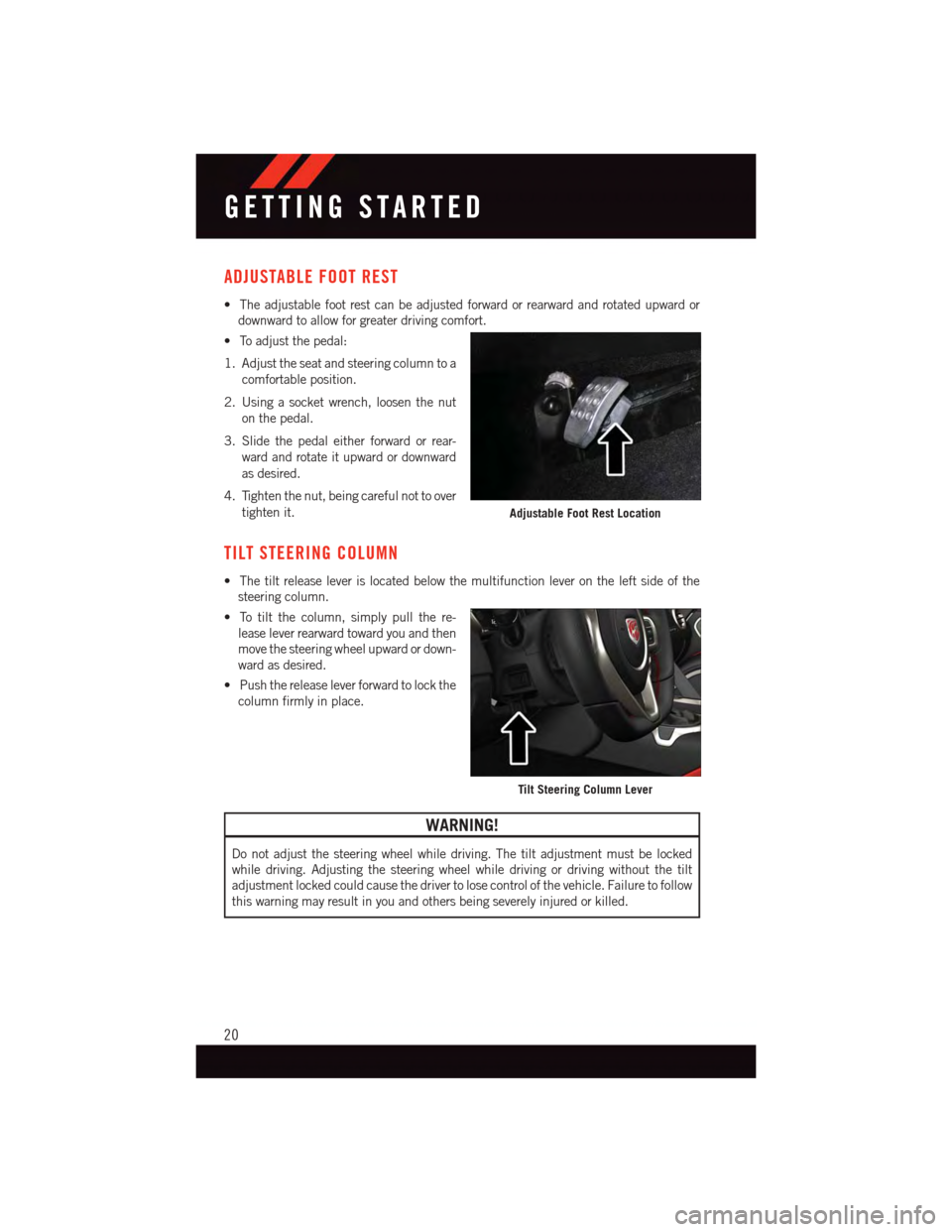
ADJUSTABLE FOOT REST
•Theadjustablefootrestcanbeadjustedforwardorrearwardandrotatedupwardor
downward to allow for greater driving comfort.
•Toadjustthepedal:
1. Adjust the seat and steering column to a
comfortable position.
2. Using a socket wrench, loosen the nut
on the pedal.
3. Slide the pedal either forward or rear-
ward and rotate it upward or downward
as desired.
4. Tighten the nut, being careful not to over
tighten it.
TILT STEERING COLUMN
•Thetiltreleaseleverislocatedbelowthemultifunctionleverontheleftsideofthe
steering column.
•Totiltthecolumn,simplypullthere-
lease lever rearward toward you and then
move the steering wheel upward or down-
ward as desired.
•Pushthereleaseleverforwardtolockthe
column firmly in place.
WARNING!
Do not adjust the steering wheel while driving. The tilt adjustment must be locked
while driving. Adjusting the steering wheel while driving or driving without the tilt
adjustment locked could cause the driver to lose control of the vehicle. Failure to follow
this warning may result in you and others being severely injured or killed.
Adjustable Foot Rest Location
Tilt Steering Column Lever
GETTING STARTED
20
Page 29 of 148
ELECTRONIC CONTROL DAMPING SYSTEM
•Thisvehiclemaybeequippedwithanelectroniccontrolleddampeningsystem.This
system reduces body roll and pitch in many driving situations including cornering,
acceleration and braking.
•Thissystemallowsforastreetsuspensiondampingsettingorafirmerracesuspension
damping setting. There are two modes of operation:
STREET MODE
•Thismodewillgiveasporty,butcomfort-
able ride.
•Thismodeisdriverselectablewhenthe
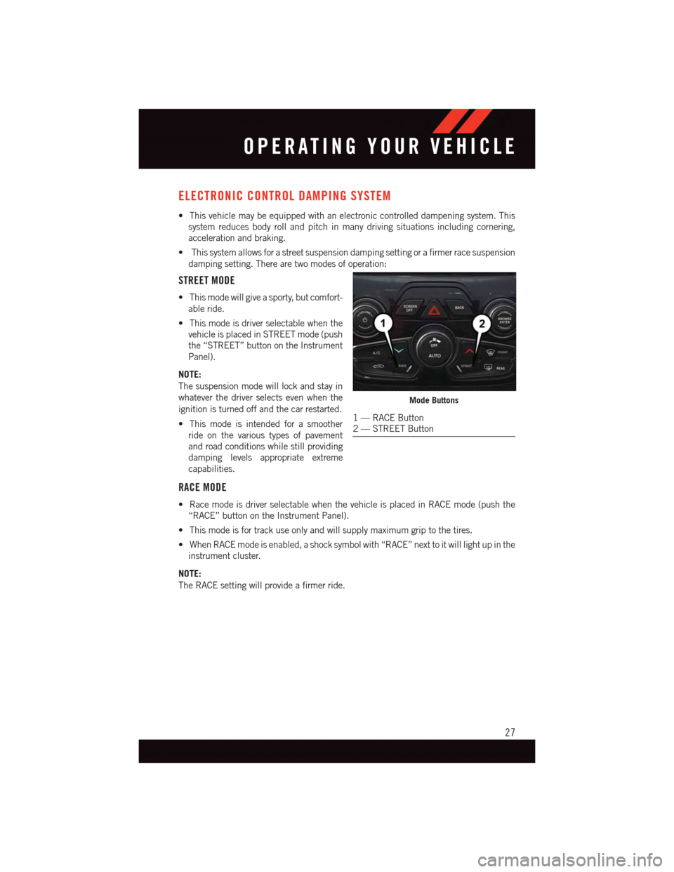
vehicle is placed in STREET mode (push
the “STREET” button on the Instrument
Panel).
NOTE:
The suspension mode will lock and stay in
whatever the driver selects even when the
ignition is turned off and the car restarted.
•Thismodeisintendedforasmoother
ride on the various types of pavement
and road conditions while still providing
damping levels appropriate extreme
capabilities.
RACE MODE
•RacemodeisdriverselectablewhenthevehicleisplacedinRACEmode(pushthe
“RACE” button on the Instrument Panel).
•Thismodeisfortrackuseonlyandwillsupplymaximumgriptothetires.
•WhenRACEmodeisenabled,ashocksymbolwith“RACE”nexttoitwilllightupinthe
instrument cluster.
NOTE:
The RACE setting will provide a firmer ride.
Mode Buttons
1—RACEButton2—STREETButton
OPERATING YOUR VEHICLE
27