FIAT 500 ABARTH 2013 2.G Repair Manual
Manufacturer: FIAT, Model Year: 2013, Model line: 500 ABARTH, Model: FIAT 500 ABARTH 2013 2.GPages: 84, PDF Size: 4.63 MB
Page 61 of 84
FREEING A STUCK VEHICLE
• If your vehicle becomes stuck in mud, sand or snow, it can often be moved by a
rocking motion. Turn your steering wheel right and left to clear the area around
the front wheels. Then shift back and forth between 1st gear and REVERSE. Us-
ing minimal accelerator pedal pressure to maintain the rocking motion, without
spinning the wheels, is most effective.
NOTE:If your vehicle is equipped with Traction Control or Electronic Stability Control (ESC), turnthe system OFF before attempting to “rock” the vehicle.
CAUTION!
• Racing the engine or spinning the wheels may lead to transmission overheat-
ing and failure. Allow the engine to idle with the shift lever in NEUTRAL for at
least one minute after every five rocking-motion cycles. This will minimize
overheating and reduce the risk of transmission failure during prolonged ef-
forts to free a stuck vehicle.
• When “rocking” a stuck vehicle by moving between 1st and REVERSE, do
not spin the wheels faster than 15 mph (24 km/h), or drivetrain damage may
result.
• Revving the engine or spinning the wheels too fast may lead to transmission
overheating and failure. It can also damage the tires. Do not spin the wheels
above 30 mph (48 km/h) while in gear (no transmission shifting occurring).
WARNING!
Fast spinning tires can be dangerous. Forces generated by excessive wheel
speeds may cause tire damage or failure. A tire could explode and injure some-
one. Do not spin your vehicle's wheels faster than 30 mph (48 km/h) when you
are stuck. Do not let anyone near a spinning wheel, no matter what the speed.
WHAT TO DO IN EMERGENCIES
59
Page 62 of 84
EVENT DATA RECORDER (EDR)
• This vehicle is equipped with an Event Data Recorder (EDR). The main purpose of
an EDR is to record, in certain crash or near crash-like situations, such as an air
bag deployment or hitting a road obstacle, data that assists in understanding
how a vehicle’s systems performed. The EDR is designed to record data related
to vehicle dynamics and safety systems for a short period of time, typically 30
seconds or less. The EDR in this vehicle is designed to record such data as:
• How various systems in your vehicle were operating.
• Whether or not the driver and passenger safety belts were buckled/fastened.
• How far (if at all) the driver was depressing the accelerator and/or brake pedal.
• How fast the vehicle was traveling.
• These data can help provide a better understanding of the circumstances in
which crashes and injuries occur.
NOTE:EDR data are recorded by your vehicle only if a non-trivial crash situation occurs; no dataare recorded by the EDR under normal driving conditions and no personal data (e.g.name, gender, age, and crash location) are recorded. However, other parties, such aslaw enforcement, could combine the EDR data with the type of personally identifyingdata routinely acquired during a crash investigation.
• To read data recorded by an EDR, special equipment is required, and access to
the vehicle or the EDR is needed. In addition to the vehicle manufacturer, other
parties such as law enforcement, that have the special equipment, can read the
information if they have access to the vehicle or the EDR.
WHAT TO DO IN EMERGENCIES
60
Page 63 of 84
OPENING THE HOOD
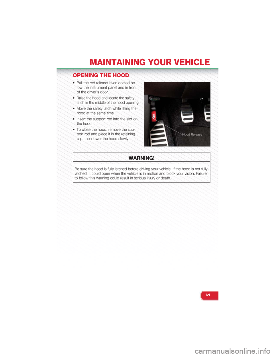
• Pull the red release lever located be-
low the instrument panel and in front
of the driver’s door.
•Raise the hood and locate the safety
latch in the middle of the hood opening.
• Move the safety latch while lifting the
hood at the same time.
• Insert the support rod into the slot on
the hood.
• To close the hood, remove the sup-
port rod and place it in the retaining
clip, then lower the hood slowly.
WARNING!
Be sure the hood is fully latched before driving your vehicle. If the hood is not fully
latched, it could open when the vehicle is in motion and block your vision. Failure
to follow this warning could result in serious injury or death.
MAINTAINING YOUR VEHICLE
61
Page 64 of 84
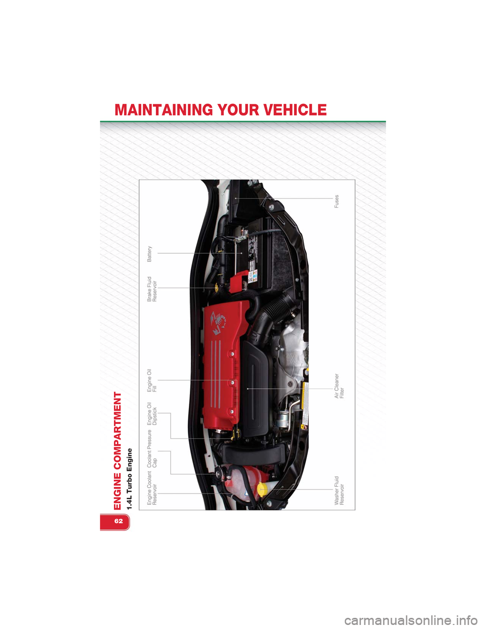
ENGINE COMPARTMENT1.4L Turbo Engine
MAINTAINING YOUR VEHICLE
62
Page 65 of 84
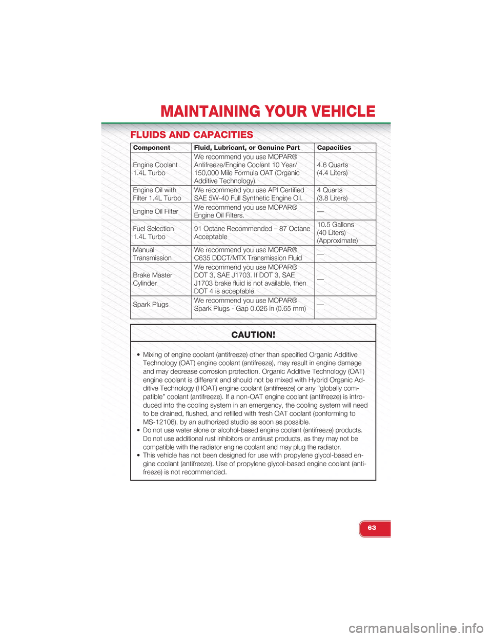
FLUIDS AND CAPACITIES
Component Fluid, Lubricant, or Genuine Part Capacities
Engine Coolant1.4L Turbo
We recommend you use MOPAR®Antifreeze/Engine Coolant 10 Year/150,000 Mile Formula OAT (OrganicAdditive Technology).
4.6 Quarts(4.4 Liters)
Engine Oil withFilter 1.4L TurboWe recommend you use API CertifiedSAE 5W-40 Full Synthetic Engine Oil.4 Quarts(3.8 Liters)
Engine Oil FilterWe recommend you use MOPAR®Engine Oil Filters.—
Fuel Selection1.4L Turbo91 Octane Recommended – 87 OctaneAcceptable
10.5 Gallons(40 Liters)(Approximate)
ManualTransmissionWe recommend you use MOPAR®C635 DDCT/MTX Transmission Fluid—
Brake MasterCylinder
We recommend you use MOPAR®DOT 3, SAE J1703. If DOT 3, SAEJ1703 brake fluid is not available, thenDOT 4 is acceptable.
—
Spark PlugsWe recommend you use MOPAR®Spark Plugs - Gap 0.026 in (0.65 mm)—
CAUTION!
• Mixing of engine coolant (antifreeze) other than specified Organic Additive
Technology (OAT) engine coolant (antifreeze), may result in engine damage
and may decrease corrosion protection. Organic Additive Technology (OAT)
engine coolant is different and should not be mixed with Hybrid Organic Ad-
ditive Technology (HOAT) engine coolant (antifreeze) or any “globally com-
patible” coolant (antifreeze). If a non-OAT engine coolant (antifreeze) is intro-
duced into the cooling system in an emergency, the cooling system will need
to be drained, flushed, and refilled with fresh OAT coolant (conforming to
MS-12106), by an authorized studio as soon as possible.
•Do not use water alone or alcohol-based engine coolant (antifreeze) products.
Do not use additional rust inhibitors or antirust products, as they may not be
compatible with the radiator engine coolant and may plug the radiator.
• This vehicle has not been designed for use with propylene glycol-based en-
gine coolant (antifreeze). Use of propylene glycol-based engine coolant (anti-
freeze) is not recommended.
MAINTAINING YOUR VEHICLE
63
Page 66 of 84
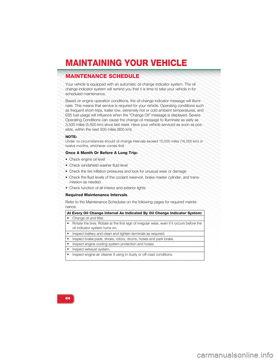
MAINTENANCE SCHEDULE
Your vehicle is equipped with an automatic oil change indicator system. The oil
change indicator system will remind you that it is time to take your vehicle in for
scheduled maintenance.
Based on engine operation conditions, the oil change indicator message will illumi-
nate. This means that service is required for your vehicle. Operating conditions such
as frequent short-trips, trailer tow, extremely hot or cold ambient temperatures, and
E85 fuel usage will influence when the “Change Oil” message is displayed. Severe
Operating Conditions can cause the change oil message to illuminate as early as
3,500 miles (5,600 km) since last reset. Have your vehicle serviced as soon as pos-
sible, within the next 500 miles (805 km).
NOTE:Under no circumstances should oil change intervals exceed 10,000 miles (16,000 km) ortwelve months, whichever comes first.
Once A Month Or Before A Long Trip:
• Check engine oil level
• Check windshield washer fluid level
• Check the tire inflation pressures and look for unusual wear or damage
• Check the fluid levels of the coolant reservoir, brake master cylinder, and trans-
mission as needed
• Check function of all interior and exterior lights
Required Maintenance Intervals.
Refer to the Maintenance Schedules on the following pages for required mainte-
nance.
At Every Oil Change Interval As Indicated By Oil Change Indicator System:
•Change oil and filter.
• Rotate the tires. Rotate at the first sign of irregular wear, even if it occurs before theoil indicator system turns on.
•Inspect battery and clean and tighten terminals as required.
•Inspect brake pads, shoes, rotors, drums, hoses and park brake.
•Inspect engine cooling system protection and hoses.
•Inspect exhaust system.
•Inspect engine air cleaner if using in dusty or off-road conditions.
MAINTAINING YOUR VEHICLE
64
Page 67 of 84
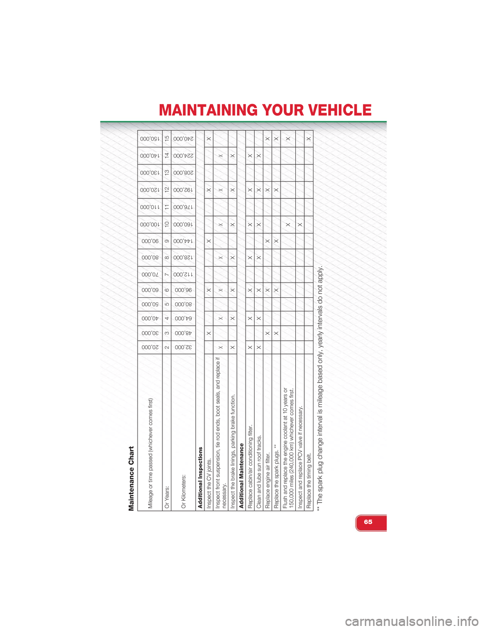
Maintenance ChartMileage or time passed (whichever comes first)
20,000
30,000
40,000
50,000
60,000
70,000
80,000
90,000
100,000
110,000
120,000
130,000
140,000
150,000
Or Years: 2 3 4 5 6 7 8 9 10 11 12 13 14 15Or Kilometers:
32,000
48,000
64,000
80,000
96,000
112,000
128,000
144,000
160,000
176,000
192,000
208,000
224,000
240,000
Additional InspectionsInspect the CV joints. X X X X XInspect front suspension, tie rod ends, boot seals, and replace ifnecessary.
XXX X X X X
Inspect the brake linings, parking brake function. X X X X X X XAdditional MaintenanceReplace cabin/air conditioning filter. X X X X X X XClean and lube sun roof tracks. X X X X X X XReplace engine air filter. X X X X XReplace the spark plugs. ** X X X X XFlush and replace the engine coolant at 10 years or150,000 miles (240,000 km) whichever comes first.
XX
Inspect and replace PCV valve if necessary.
X
Replace the timing belt.
X
** The spark plug change interval is mileage based only, yearly intervals do not apply.
MAINTAINING YOUR VEHICLE
65
Page 68 of 84
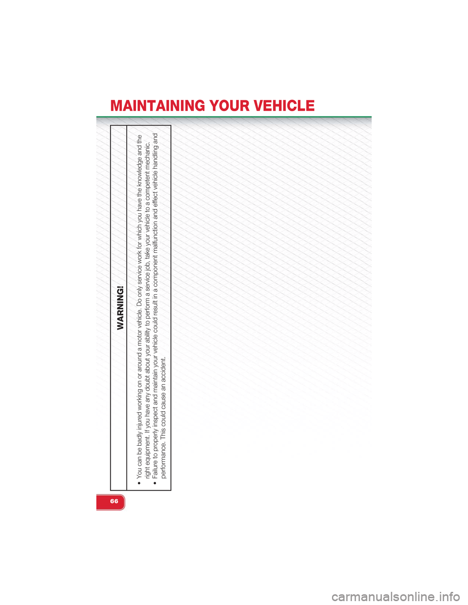
WARNING!
•You can be badly injured working on or around a motor vehicle. Do only service work for which you have the knowledge and theright equipment. If you have any doubt about your ability to perform a service job, take your vehicle to a competent mechanic.• Failure to properly inspect and maintain your vehicle could result in a component malfunction and effect vehicle handling andperformance. This could cause an accident.
MAINTAINING YOUR VEHICLE
66
Page 69 of 84
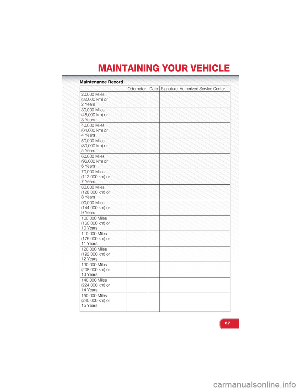
Maintenance Record
Odometer DateSignature, Authorized Service Center
20,000 Miles(32,000 km) or2 Years
30,000 Miles(48,000 km) or3 Years
40,000 Miles(64,000 km) or4 Years
50,000 Miles(80,000 km) or5 Years
60,000 Miles(96,000 km) or6 Years
70,000 Miles(112,000 km) or7 Years
80,000 Miles(128,000 km) or8 Years
90,000 Miles(144,000 km) or9 Years
100,000 Miles(160,000 km) or10 Years
110,000 Miles(176,000 km) or11 Years
120,000 Miles(192,000 km) or12 Years
130,000 Miles(208,000 km) or13 Years
140,000 Miles(224,000 km) or14 Years
150,000 Miles(240,000 km) or15 Years
MAINTAINING YOUR VEHICLE
67
Page 70 of 84
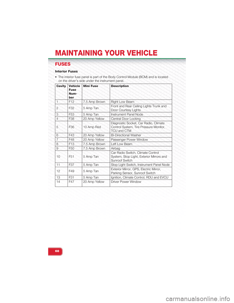
FUSES
Interior Fuses
• The interior fuse panel is part of the Body Control Module (BCM) and is located
on the driver's side under the instrument panel.
Cavity VehicleFuseNum-ber
Mini Fuse Description
1 F12 7.5 Amp Brown Right Low Beam
2 F32 5 Amp TanFront and Rear Ceiling Lights Trunk andDoor Courtesy Lights
3 F53 5 Amp Tan Instrument Panel Node
4 F38 20 Amp Yellow Central Door Locking
5 F36 10 Amp RedDiagnostic Socket, Car Radio, ClimateControl System, Tire Pressure Monitor,TCU and CTM
6 F43 20 Amp Yellow Bi-Directional Washer
7 F48 20 Amp Yellow Passenger Power Window
8 F13 7.5 Amp Brown Left Low Beam
9 F50 7.5 Amp Brown Airbag
10 F51 5 Amp TanCar Radio Switch, Climate ControlSystem, Stop Light, Exterior Mirrors andSunroof Switch
11 F37 5 Amp Tan Stop Light Switch, Instrument Panel Node
12 F49 5 Amp TanExterior Mirror, GPS, Electric Mirror,Parking Sensor, Sunroof Switch
13 F31 5 Amp Tan Ignition, Climate Control, RDU and EVCU
14 F47 20 Amp Yellow Driver Power Window
MAINTAINING YOUR VEHICLE
68