engine FIAT 500X 2017 Owner handbook (in English)
[x] Cancel search | Manufacturer: FIAT, Model Year: 2017, Model line: 500X, Model: FIAT 500X 2017Pages: 284, PDF Size: 11.14 MB
Page 132 of 284
DRIVE MODE
The device allows the driver to
select three different driving
modes (car response) according to their
needs and to the road and traffic
conditions, by manually adjusting the
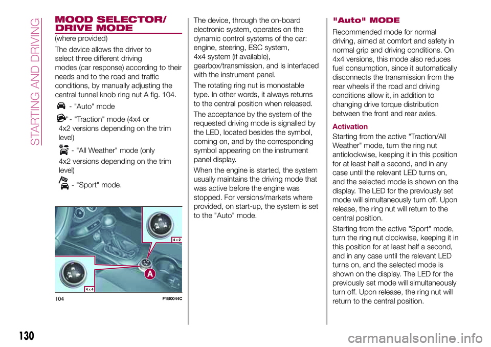
central tunnel knob ring nut A fig. 104.
- "Auto" mode
- "Traction" mode (4x4 or
4x2 versions depending on the trim
level)
- "All Weather" mode (only
4x2 versions depending on the trim
level)
- "Sport" mode.The device, through the on-board
electronic system, operates on the
dynamic control systems of the car:
engine, steering, ESC system,
4x4 system (if available),
gearbox/transmission, and is interfaced
with the instrument panel.
The rotating ring nut is monostable
type. In other words, it always returns
to the central position when released.
The acceptance by the system of the
requested driving mode is signalled by
the LED, located besides the symbol,
coming on, and by the corresponding
symbol appearing on the instrument
panel display.
When the engine is started, the system
usually maintains the driving mode that
was active before the engine was
stopped. For versions/markets where
provided, on start-up, the system is set
to the "Auto" mode.
"Auto" MODE
Recommended mode for normal
driving, aimed at comfort and safety in
normal grip and driving conditions. On
4x4 versions, this mode also reduces
fuel consumption, since it automatically
disconnects the transmission from the
rear wheels if the road and driving
conditions allow it, in addition to
changing drive torque distribution
between the front and rear axles.
Activation
Starting from the active "Traction/All
Weather" mode, turn the ring nut
anticlockwise, keeping it in this position
for at least half a second, and in any
case until the relevant LED turns on,
and the selected mode is shown on the
display. The LED for the previously set
mode will simultaneously turn off. Upon
release, the ring nut will return to the
central position.
Starting from the active "Sport" mode,
turn the ring nut clockwise, keeping it in
this position for at least half a second,
and in any case until the relevant LED
turns on, and the selected mode is
shown on the display. The LED for the
previously set mode will simultaneously
turn off. Upon release, the ring nut will
return to the central position.
104F1B0044C
130
STARTING AND DRIVING
(where provided)
MOOD SELECTOR/
Page 136 of 284
LANE ASSIST
SYSTEM (lane
crossing warning)
DESCRIPTION
57) 58) 59) 60) 61) 62)
The Lane Assist system makes use of a
camera located on the windscreen to
detect the lane limits and calculate the
position of the vehicle within such limits,
in order to make sure that it remains
inside the lane.
When both limits of the lane are
detected and the vehicle crosses one of
them without the awareness of the
driver (direction indicator off), the Lane
Assist system provides a tactile warning
by applying torque to the steering wheel
(vibration), thus advising the driver that
he must take an action to remain in the
lane.
IMPORTANT The torque applied to the
steering wheel by the system is
sufficient for the driver to notice it, but
always limited, so that they can easily
override it, and the driver always
maintains control of the vehicle. The
driver can therefore turn the steering
wheel as required at all times.
If the vehicle continues going beyond
the line of the lane without anyintervention from the driver, the
warning light (or the icon on the
display) will be displayed on the
instrument panel to urge the driver to
bring the vehicle back into the limits of
the lane.
IMPORTANT The system monitors the
presence of the driver's hands on the
steering wheel. If they are not detected,
the system emits an acoustic signal and
deactivates until it is reactivated by
pressing the dedicated button (see
description below).
When one limit of the lane is detected
and the vehicle crosses it (direction
indicator off), warning light
(or the
icon on the display) will be displayed on
the instrument panel to urge the driver
to bring the vehicle back into the lane.
In this case, the tactile warning
(vibration on the steering wheel) is not
provided.
SYSTEM ACTIVATION/
DEACTIVATION
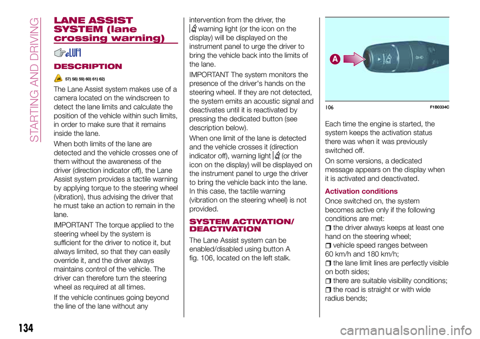
The Lane Assist system can be
enabled/disabled using button A
fig. 106, located on the left stalk.Each time the engine is started, the
system keeps the activation status
there was when it was previously
switched off.
On some versions, a dedicated
message appears on the display when
it is activated and deactivated.
Activation conditions
Once switched on, the system
becomes active only if the following
conditions are met:
the driver always keeps at least one
hand on the steering wheel;
vehicle speed ranges between
60 km/h and 180 km/h;
the lane limit lines are perfectly visible
on both sides;
there are suitable visibility conditions;
the road is straight or with wide
radius bends;
106F1B0334C
134
STARTING AND DRIVING
Page 139 of 284
Do not exceed the speed limits specific
to each country you are driving in, in the
case of vehicles towing trailers. In any
case, the top speed must not exceed
100 km/h.
Any electric brake must be powered
directly by the battery through a cable
with a cross-section of no less than
2.5 mm
2. In addition to the electrical
branches, the vehicle electrical system
can only be connected to the supply
cable for an electric brake and to the
cable for an internal light for the trailer,
not exceeding 15 W. For connections,
use the preset control unit with a
battery cable with section not less than
2.5 mm
2. The use of auxiliary loads
other than external lights (e.g. electric
brake) must take place with engine
running.
INSTALLING A TOW
HOOK
The towing device should be fastened
to the body by specialised personnel
according to any additional and/or
integrative information supplied by the
Manufacturer of the device. It must also
meet current regulations with reference
to Directive 94/20/EC and subsequent
amendments.
For any version the towing device used
must be right for the towable weight of
the vehicle on which it is to be installed.
For the electrical connection a standard
connector should be used which is
generally placed on a special bracket
normally fastened to the towing device,
and a special ECU for external trailer
light control must be installed on the
vehicle. 7 or 13-pin 12 V DC
connections should be used
(CUNA/UNI and ISO/DIN Standards).
Follow any instructions provided by the
vehicle manufacturer and/or the towing
device manufacturer.
137
Page 142 of 284
REFUELLING THE
VEHICLE
133) 134) 135)
PETROL ENGINES
Only use unleaded petrol with a number
of octanes (R.O.N.) not lower than 95
(EN 228 specification).
DIESEL ENGINES
64)
Only use Diesel for motor vehicles (EN
590 specification).
When using or parking the vehicle for a
long time in the mountains or cold
areas, it is advisable to refuel using
locally available diesel. In this case, it is
also advisable to keep the tank over
50% full.
REFUELLING
PROCEDURE
"Capless Fuel" is a device at the
opening for the fuel tank which opens
and recloses automatically when the
fuel supply gun is introduced/removed.
The "Capless Fuel" device is provided
with an inhibitor which prevents
refuelling with incorrect fuel.
Opening the flap
To refuel proceed as follows:
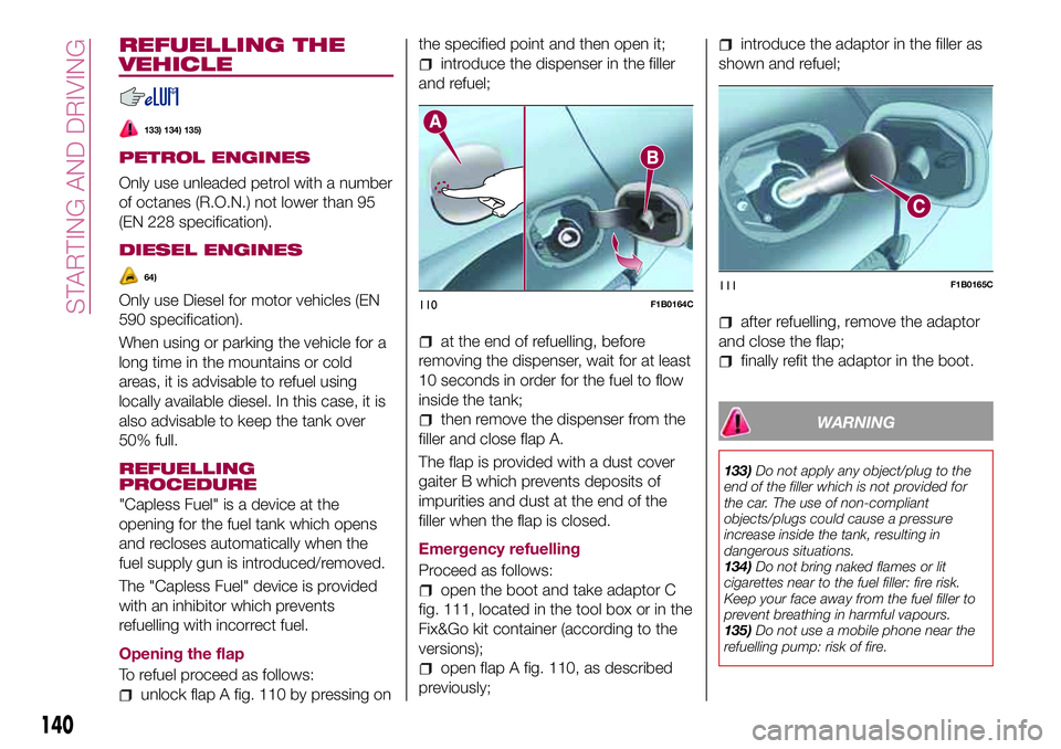
unlock flap A fig. 110 by pressing onthe specified point and then open it;
introduce the dispenser in the filler
and refuel;
at the end of refuelling, before
removing the dispenser, wait for at least
10 seconds in order for the fuel to flow
inside the tank;
then remove the dispenser from the
filler and close flap A.
The flap is provided with a dust cover
gaiter B which prevents deposits of
impurities and dust at the end of the
filler when the flap is closed.
Emergency refuelling
Proceed as follows:
open the boot and take adaptor C
fig. 111, located in the tool box or in the
Fix&Go kit container (according to the
versions);
open flap A fig. 110, as described
previously;
introduce the adaptor in the filler as
shown and refuel;
after refuelling, remove the adaptor
and close the flap;
finally refit the adaptor in the boot.
WARNING
133)Do not apply any object/plug to the
end of the filler which is not provided for
the car. The use of non-compliant
objects/plugs could cause a pressure
increase inside the tank, resulting in
dangerous situations.
134)Do not bring naked flames or lit
cigarettes near to the fuel filler: fire risk.
Keep your face away from the fuel filler to
prevent breathing in harmful vapours.
135)Do not use a mobile phone near the
refuelling pump: risk of fire.
110F1B0164C111F1B0165C
140
STARTING AND DRIVING
Page 143 of 284
IMPORTANT
64)Vehicles with a diesel engine must only
be filled with diesel fuel for motor vehicles,
in compliance with European Standard EN
590. The use of other products or mixtures
may damage the engine beyond repair and
consequently invalidate the warranty, due
to the damage caused. If you accidentally
introduce other types of fuel into the tank,
do not start the engine. Empty the tank. If
the engine has been run for even an
extremely limited amount of time, you must
not only drain the fuel tank, but the rest of
the supply circuit as well.
Fuels - identification of
vehicle compatibility
Symbol for consumer
information in
accordance with the
EN16942 specification
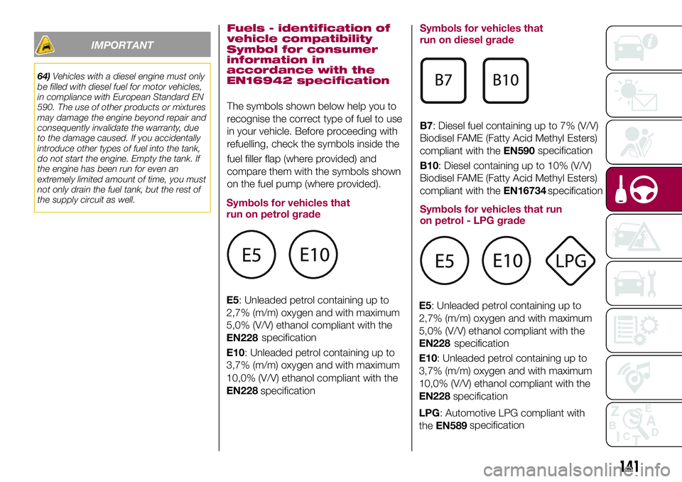
The symbols shown below help you to
recognise the correct type of fuel to use
in your vehicle. Before proceeding with
refuelling, check the symbols inside the
fuel filler flap (where provided) and
compare them with the symbols shown
on the fuel pump (where provided).
Symbols for vehicles that
run on petrol grade
E5: Unleaded petrol containing up to
2,7% (m/m) oxygen and with maximum
5,0% (V/V) ethanol compliant with the
EN228
E10: Unleaded petrol containing up to
3,7% (m/m) oxygen and with maximum
10,0% (V/V) ethanol compliant with the
EN228Symbols for vehicles that
run on diesel grade
B7: Diesel fuel containing up to 7% (V/V)
Biodisel FAME (Fatty Acid Methyl Esters)
compliant with theEN590
B10: Diesel containing up to 10% (V/V)
Biodisel FAME (Fatty Acid Methyl Esters)
compliant with theEN16734
Symbols for vehicles that run
on petrol - LPG grade
LPG: Automotive LPG compliant with
theEN589
141
specification
specificationspecification
specification
E5: Unleaded petrol containing up to
2,7% (m/m) oxygen and with maximum
5,0% (V/V) ethanol compliant with the
EN228
E10: Unleaded petrol containing up to
3,7% (m/m) oxygen and with maximum
10,0% (V/V) ethanol compliant with the
EN228specification
specification
specification
Page 148 of 284
REPLACING AN
EXTERNAL BULB
Dipped/main beam headlights
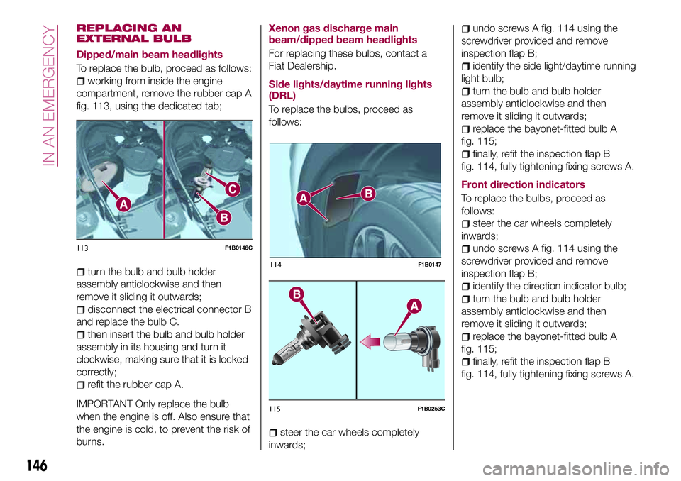
To replace the bulb, proceed as follows:
working from inside the engine
compartment, remove the rubber cap A
fig. 113, using the dedicated tab;
turn the bulb and bulb holder
assembly anticlockwise and then
remove it sliding it outwards;
disconnect the electrical connector B
and replace the bulb C.
then insert the bulb and bulb holder
assembly in its housing and turn it
clockwise, making sure that it is locked
correctly;
refit the rubber cap A.
IMPORTANT Only replace the bulb
when the engine is off. Also ensure that
the engine is cold, to prevent the risk of
burns.
Xenon gas discharge main
beam/dipped beam headlights
For replacing these bulbs, contact a
Fiat Dealership.
Side lights/daytime running lights
(DRL)
To replace the bulbs, proceed as
follows:
steer the car wheels completely
inwards;
undo screws A fig. 114 using the
screwdriver provided and remove
inspection flap B;
identify the side light/daytime running
light bulb;
turn the bulb and bulb holder
assembly anticlockwise and then
remove it sliding it outwards;
replace the bayonet-fitted bulb A
fig. 115;
finally, refit the inspection flap B
fig. 114, fully tightening fixing screws A.
Front direction indicators
To replace the bulbs, proceed as
follows:
steer the car wheels completely
inwards;
undo screws A fig. 114 using the
screwdriver provided and remove
inspection flap B;
identify the direction indicator bulb;
turn the bulb and bulb holder
assembly anticlockwise and then
remove it sliding it outwards;
replace the bayonet-fitted bulb A
fig. 115;
finally, refit the inspection flap B
fig. 114, fully tightening fixing screws A.
113F1B0146C
115F1B0253C
146
IN AN EMERGENCY
114F1B0147
Page 151 of 284
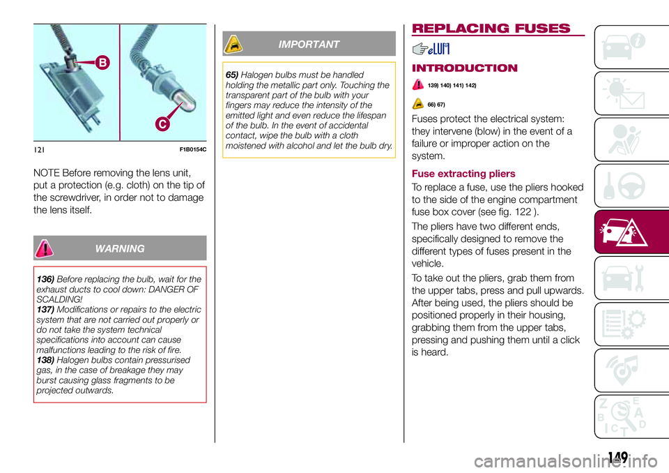
NOTE Before removing the lens unit,
put a protection (e.g. cloth) on the tip of
the screwdriver, in order not to damage
the lens itself.
WARNING
136)Before replacing the bulb, wait for the
exhaust ducts to cool down: DANGER OF
SCALDING!
137)Modifications or repairs to the electric
system that are not carried out properly or
do not take the system technical
specifications into account can cause
malfunctions leading to the risk of fire.
138)Halogen bulbs contain pressurised
gas, in the case of breakage they may
burst causing glass fragments to be
projected outwards.
IMPORTANT
65)Halogen bulbs must be handled
holding the metallic part only. Touching the
transparent part of the bulb with your
fingers may reduce the intensity of the
emitted light and even reduce the lifespan
of the bulb. In the event of accidental
contact, wipe the bulb with a cloth
moistened with alcohol and let the bulb dry.
REPLACING FUSES
INTRODUCTION
139) 140) 141) 142)
66) 67)
Fuses protect the electrical system:
they intervene (blow) in the event of a
failure or improper action on the
system.
Fuse extracting pliers
To replace a fuse, use the pliers hooked
to the side of the engine compartment
fuse box cover (see fig. 122 ).
The pliers have two different ends,
specifically designed to remove the
different types of fuses present in the
vehicle.
To take out the pliers, grab them from
the upper tabs, press and pull upwards.
After being used, the pliers should be
positioned properly in their housing,
grabbing them from the upper tabs,
pressing and pushing them until a click
is heard.
121F1B0154C
149
Page 152 of 284
FUSE LOCATION
Fuses are grouped together in the fuse
boxes located in the engine
compartment, under the dashboard
and inside the boot.
ENGINE COMPARTMENT
FUSE BOX
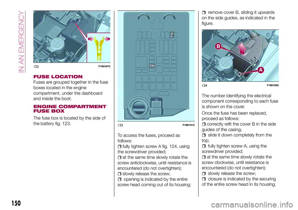
The fuse box is located by the side of
the battery fig. 123.
To access the fuses, proceed as
follows:
fully tighten screw A fig. 124, using
the screwdriver provided;
at the same time slowly rotate the
screw anticlockwise, until resistance is
encountered (do not overtighten);
slowly release the screw;
opening is indicated by the entire
screw head coming out of its housing;
remove cover B, sliding it upwards
on the side guides, as indicated in the
figure.
The number identifying the electrical
component corresponding to each fuse
is shown on the cover.
Once the fuse has been replaced,
proceed as follows:
correctly refit the cover B in the side
guides of the casing;
slide it down completely from the
top;
fully tighten screw A, using the
screwdriver provided;
at the same time slowly rotate the
screw clockwise, until resistance is
encountered (do not overtighten);
slowly release the screw;
closure is indicated by the securing
of the entire screw head in its housing.
122F1B0187C
123F1B0191C
124F1B0190C
150
IN AN EMERGENCY
Page 155 of 284
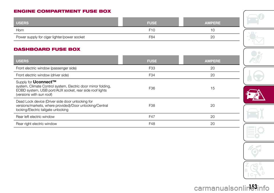
ENGINE COMPARTMENT FUSE BOX
USERSFUSE AMPERE
HornF10 10
Power supply for cigar lighter/power socket F84 20
DASHBOARD FUSE BOX
USERSFUSE AMPERE
Front electric window (passenger side) F33 20
Front electric window (driver side) F34 20
Supply for
Uconnect™system, Climate Control system, Electric door mirror folding,
EOBD system, USB port/AUX socket, rear side roof lights
(versions with sun roof)F36 15
Dead Lock device (Driver side door unlocking for
versions/markets, where provided)/Door unlocking/Central
locking/Electric tailgate unlockingF38 20
Rear left electric window F47 20
Rear right electric window F48 20
153
Page 157 of 284
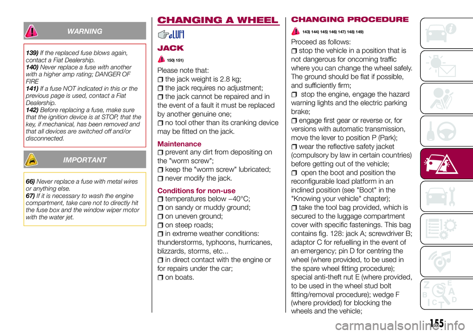
WARNING
139)If the replaced fuse blows again,
contact a Fiat Dealership.
140)Never replace a fuse with another
with a higher amp rating; DANGER OF
FIRE
141)If a fuse NOT indicated in this or the
previous page is used, contact a Fiat
Dealership.
142)Before replacing a fuse, make sure
that the ignition device is at STOP, that the
key, if mechanical, has been removed and
that all devices are switched off and/or
disconnected.
IMPORTANT
66)Never replace a fuse with metal wires
or anything else.
67)If it is necessary to wash the engine
compartment, take care not to directly hit
the fuse box and the window wiper motor
with the water jet.
CHANGING A WHEEL
JACK
150) 151)
Please note that:
the jack weight is 2.8 kg;
the jack requires no adjustment;
the jack cannot be repaired and in
the event of a fault it must be replaced
by another genuine one;
no tool other than its cranking device
may be fitted on the jack.
Maintenance
prevent any dirt from depositing on
the "worm screw";
keep the "worm screw" lubricated;
never modify the jack.
Conditions for non-use
temperatures below −40°C;
on sandy or muddy ground;
on uneven ground;
on steep roads;
in extreme weather conditions:
thunderstorms, typhoons, hurricanes,
blizzards, storms, etc...
in direct contact with the engine or
for repairs under the car;
on boats.
CHANGING PROCEDURE
143) 144) 145) 146) 147) 148) 149)
Proceed as follows:
stop the vehicle in a position that is
not dangerous for oncoming traffic
where you can change the wheel safely.
The ground should be flat if possible,
and sufficiently firm;
stop the engine, engage the hazard
warning lights and the electric parking
brake;
engage first gear or reverse or, for
versions with automatic transmission,
move the lever to position P (Park);
wear the reflective safety jacket
(compulsory by law in certain countries)
before getting out of the vehicle;
open the boot and position the
reconfigurable load platform in an
inclined position (see "Boot" in the
"Knowing your vehicle" chapter);
take the tool bag provided, which is
secured to the luggage compartment
cover with specific fastenings. This bag
contains fig. 128: jack A; screwdriver B;
adaptor C for refuelling in the event of
an emergency; pin D for centring the
wheel (where provided, to be used in
the spare wheel fitting procedure);
special anti-theft nut E (where provided,
to be used in the wheel stud bolt
fitting/removal procedure); wedge F
wheels and the vehicle;
155
(where provided) for blocking the