buttons FIAT 500X 2017 Owner handbook (in English)
[x] Cancel search | Manufacturer: FIAT, Model Year: 2017, Model line: 500X, Model: FIAT 500X 2017Pages: 284, PDF Size: 11.14 MB
Page 12 of 284
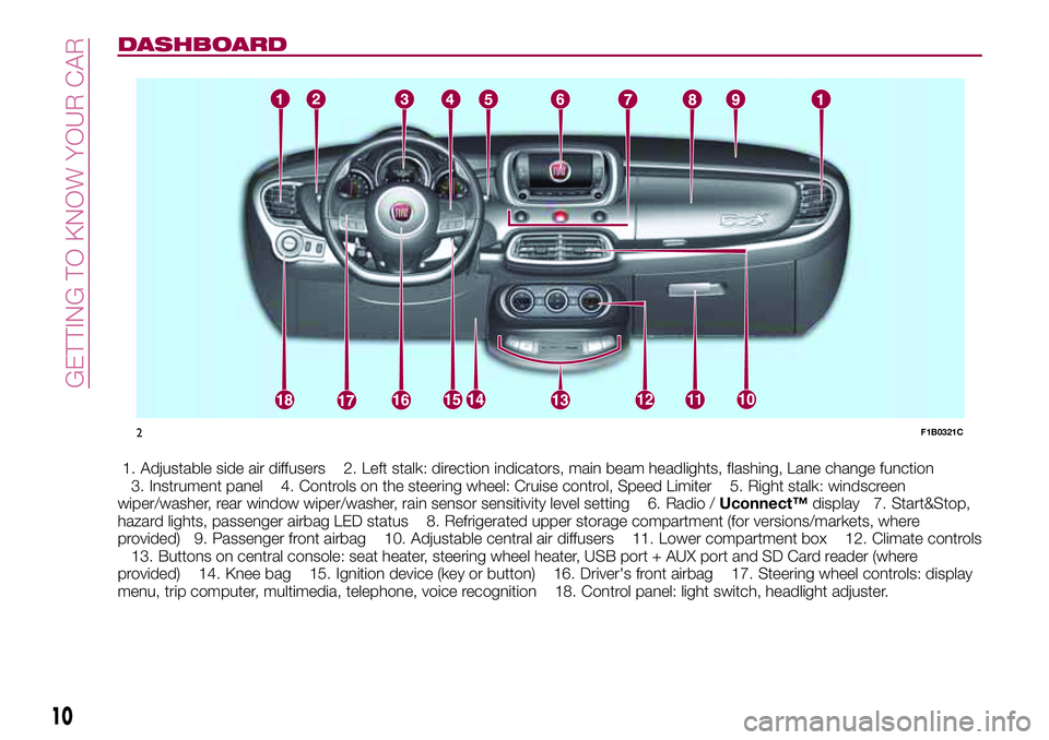
DASHBOARD
1. Adjustable side air diffusers 2. Left stalk: direction indicators, main beam headlights, flashing, Lane change function
3. Instrument panel 4. Controls on the steering wheel: Cruise control, Speed Limiter 5. Right stalk: windscreen
wiper/washer, rear window wiper/washer, rain sensor sensitivity level setting 6. Radio /Uconnect™display 7. Start&Stop,
hazard lights, passenger airbag LED status 8. Refrigerated upper storage compartment (for versions/markets, where
provided) 9. Passenger front airbag 10. Adjustable central air diffusers 11. Lower compartment box 12. Climate controls
13. Buttons on central console: seat heater, steering wheel heater, USB port + AUX port and SD Card reader (where
provided) 14. Knee bag 15. Ignition device (key or button) 16. Driver's front airbag 17. Steering wheel controls: display
menu, trip computer, multimedia, telephone, voice recognition 18. Control panel: light switch, headlight adjuster.
1211
2F1B0321C
10
GETTING TO KNOW YOUR CAR
Page 21 of 284
IMPORTANT Carry out the adjustment
while sitting on the seat involved (driver
side or passenger side).
Backrest angle adjustment
Move lever C to adjust the backrest
angle, accompanying it with the
movement of the torso (operate the
lever until the desired position is
reached, then release it).
Electric lumbar adjustment
When the ignition device is at MAR,
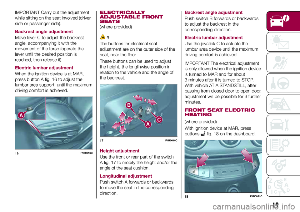
press button A fig. 16 to adjust the
lumbar area support, until the maximum
driving comfort is achieved.
ELECTRICALLY
ADJUSTABLE FRONT
SEATS
(where provided)
5)
The buttons for electrical seat
adjustment are on the outer side of the
seat, near the floor.
These buttons can be used to adjust
the height, the lengthwise position in
relation to the vehicle and the angle of
the backrest.
Height adjustment
Use the front or rear part of the switch
A fig. 17 to modify the height and/or the
angle of the seat cushion.
Longitudinal adjustment
Push switch A forwards or backwards
to move the seat in the corresponding
direction.Backrest angle adjustment
Push switch B forwards or backwards
to adjust the backrest in the
corresponding direction.
Electric lumbar adjustment
Use the joystick C to actuate the
lumbar area device until the maximum
driving comfort is achieved.
IMPORTANT The electrical adjustment
is only allowed when the ignition device
is turned to MAR and for about
3 minutes after it is turned to STOP.
With vehicle AT A STANDSTILL, after
passing from closed door to open door,
adjustment will be possible for 3 further
minutes.
FRONT SEAT ELECTRIC
HEATING
(where provided)
With ignition device at MAR, press
buttons
fig. 18 on the dashboard.
16F1B0016C
17F1B0018C
18F1B0021C
19
Page 22 of 284
You can select two heating levels:
"minimum heating": (one orange
LED lit on the buttons);
"maximum heating": two orange
LEDs lit on the buttons.
After selecting one heating level, you
need to wait for a few minutes until
warm air flows into the compartment.
When the "maximum heating" setting is
selected, the heater produces a
boosted heat level for the first minutes
of operation.
IMPORTANT To preserve the battery
charge, this function cannot be
activated when the engine is off.
REAR SEATS
Partial extension of the boot (1/3 or
2/3)
13)
6)
remove the rear shelf;
completely lower the rear seat head
restraints;
move the seat belt to the side,
making sure that it is fully extended and
not twisted;
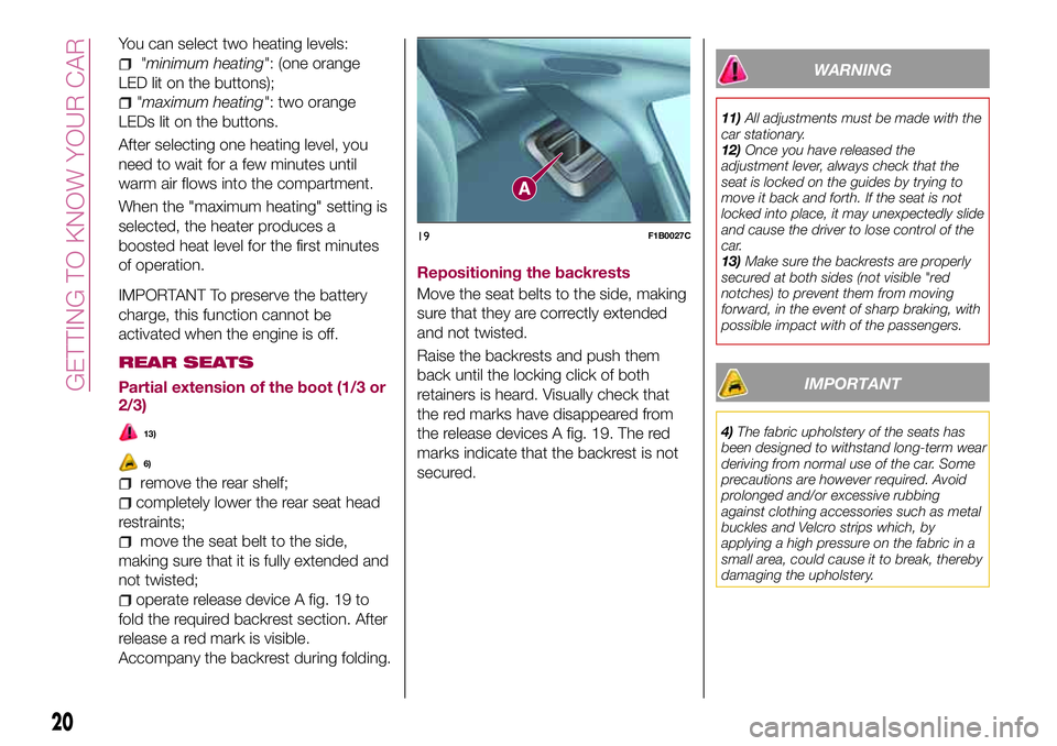
operate release device A fig. 19 to
fold the required backrest section. After
release a red mark is visible.
Accompany the backrest during folding.Repositioning the backrests
Move the seat belts to the side, making
sure that they are correctly extended
and not twisted.
Raise the backrests and push them
back until the locking click of both
retainers is heard. Visually check that
the red marks have disappeared from
the release devices A fig. 19. The red
marks indicate that the backrest is not
secured.
WARNING
11)All adjustments must be made with the
car stationary.
12)Once you have released the
adjustment lever, always check that the
seat is locked on the guides by trying to
move it back and forth. If the seat is not
locked into place, it may unexpectedly slide
and cause the driver to lose control of the
car.
13)Make sure the backrests are properly
secured at both sides (not visible "red
notches) to prevent them from moving
forward, in the event of sharp braking, with
possible impact with of the passengers.
IMPORTANT
4)The fabric upholstery of the seats has
been designed to withstand long-term wear
deriving from normal use of the car. Some
precautions are however required. Avoid
prolonged and/or excessive rubbing
against clothing accessories such as metal
buckles and Velcro strips which, by
applying a high pressure on the fabric in a
small area, could cause it to break, thereby
damaging the upholstery.
19F1B0027C
20
GETTING TO KNOW YOUR CAR
Page 23 of 284
5)Do not arrange objects beneath the
electrically adjustable seat and do not
impede its movement, since the controls
may be damaged. The fabric upholstery for
the seats has been designed to withstand
long-term wear deriving from normal use of
the vehicle. Some precautions are however
required. Avoid prolonged and/or excessive
rubbing against clothing accessories such
as metal buckles and Velcro strips which,
by applying a high pressure on the fabric in
a small area, could cause it to break,
thereby damaging the upholstery. They
may also restrict the seat travel.
6)Before tilting the backrest, remove any
objects on the seat cushion.HEAD RESTRAINTS
FRONT
14)
Adjustment
They can be adjusted to 4 height
positions (completely raised /
2 intermediate positions / completely
lowered).
Upward adjustment: raise the head
restraint until it clicks into place.
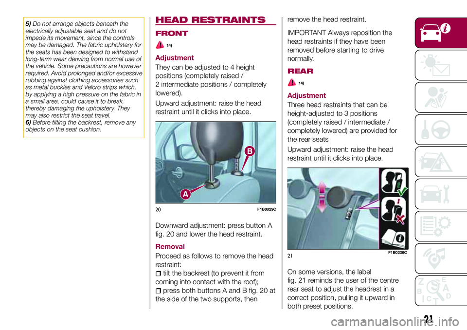
Downward adjustment: press button A
fig. 20 and lower the head restraint.
Removal
Proceed as follows to remove the head
restraint:
tilt the backrest (to prevent it from
coming into contact with the roof);
press both buttons A and B fig. 20 at
the side of the two supports, thenremove the head restraint.
IMPORTANT Always reposition the
head restraints if they have been
removed before starting to drive
normally.
REAR
14)
Adjustment
Three head restraints that can be
height-adjusted to 3 positions
(completely raised / intermediate /
completely lowered) are provided for
the rear seats
Upward adjustment: raise the head
restraint until it clicks into place.
On some versions, the label
fig. 21 reminds the user of the centre
rear seat to adjust the headrest in a
correct position, pulling it upward in
both preset positions.
20F1B0029C
21F1B0236C
21
Page 24 of 284
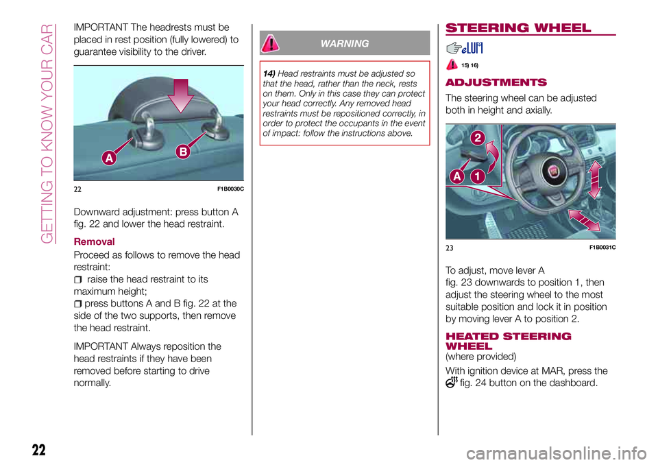
IMPORTANT The headrests must be
placed in rest position (fully lowered) to
guarantee visibility to the driver.
Downward adjustment: press button A
fig. 22 and lower the head restraint.
Removal
Proceed as follows to remove the head
restraint:
raise the head restraint to its
maximum height;
press buttons A and B fig. 22 at the
side of the two supports, then remove
the head restraint.
IMPORTANT Always reposition the
head restraints if they have been
removed before starting to drive
normally.
WARNING
14)Head restraints must be adjusted so
that the head, rather than the neck, rests
on them. Only in this case they can protect
your head correctly. Any removed head
restraints must be repositioned correctly, in
order to protect the occupants in the event
of impact: follow the instructions above.
STEERING WHEEL
15) 16)
ADJUSTMENTS
The steering wheel can be adjusted
both in height and axially.
To adjust, move lever A
fig. 23 downwards to position 1, then
adjust the steering wheel to the most
suitable position and lock it in position
by moving lever A to position 2.
HEATED STEERING
WHEEL
(where provided)
With ignition device at MAR, press the
fig. 24 button on the dashboard.
22F1B0030C
23F1B0031C
22
GETTING TO KNOW YOUR CAR
Page 37 of 284
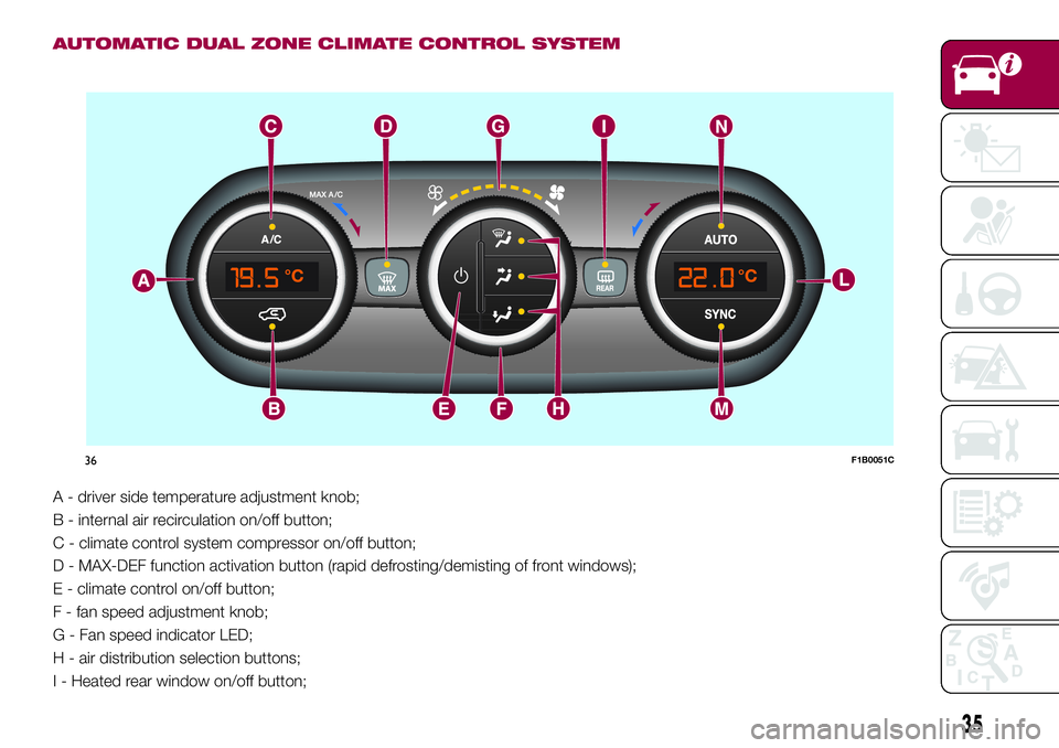
AUTOMATIC DUAL ZONE CLIMATE CONTROL SYSTEM
A - driver side temperature adjustment knob;
B - internal air recirculation on/off button;
C - climate control system compressor on/off button;
D - MAX-DEF function activation button (rapid defrosting/demisting of front windows);
E - climate control on/off button;
F - fan speed adjustment knob;
G - Fan speed indicator LED;
H - air distribution selection buttons;
I - Heated rear window on/off button;
36F1B0051C
35
Page 38 of 284
L - passenger side temperature adjustment knob;
M - SYNC function activation button (alignment of set temperatures) driver/passenger side;
N - AUTO function activation button (automatic operation).
Air distribution selection
Air flow to the windscreen and front side window diffusers to demist/defrost them.
Air flow at central and side dashboard vents to ventilate the chest and the face during the hot season.
Air flow to the front and rear footwell diffusers. This air distribution setting heats the passenger compartment most quickly,
giving a prompt sensation of warmth.
+Air flow distributed between footwell diffusers (hotter air) and central and side dashboard vents (cooler air). This
distribution setting is useful in spring and autumn on sunny days.
+Air flow distributed between footwell vents and windscreen and front side vents. This distribution setting allows the
passenger compartment to be warmed up efficiently and prevents the windows from misting up.
+Air flow distributed between central and side dashboard vents and windscreen and front side window vents. This
distribution allows air to be sent to the windscreen in conditions of strong sunlight.
++Air flow distribution to all diffusers on the vehicle.
In AUTO mode, the climate control system automatically manages air distribution (the LEDs on buttons H are off). When set
manually, the air distribution is indicated by the LEDs on the selected buttons switching on. In combined function mode the
relevant function is enabled simultaneously with those already set by pressing the corresponding button. If a button whose
function is already active is pressed, its operation is cancelled and the corresponding LED switches off. To restore automatic
control of the air distribution after a manual selection, press the AUTO button.
Start&Stop
The automatic dual zone climate control system manages the Start&Stop system (engine off when vehicle speed is 0 km/h) to
ensure adequate comfort inside the vehicle. When the Start&Stop system is on (engine off and vehicle at a standstill), the
automatic recirculation management is turned off always taking air in from outside, to reduce the probability of the windows
misting up (as the compressor is off).
IMPORTANT
2)The system uses R1234YF coolant, which does not pollute the environment in the event of accidental leakage. Under no circumstances
use R134a and R12 fluids, which are incompatible with the components of the system.
36
GETTING TO KNOW YOUR CAR
Page 39 of 284
ELECTRIC WINDOWS
21)
Electric windows operate with the
ignition device at MAR and for about
3 minutes after the ignition device
switches to STOP (or key removed).
When one of the front doors is opened
this operation is disabled.
Driver side front door controls
All windows can be controlled from the
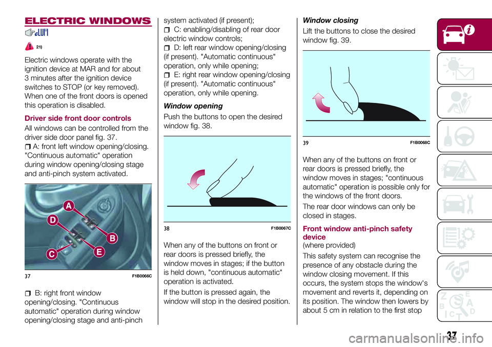
driver side door panel fig. 37.
A: front left window opening/closing.
"Continuous automatic" operation
during window opening/closing stage
and anti-pinch system activated.
B: right front window
opening/closing. "Continuous
automatic" operation during window
opening/closing stage and anti-pinchsystem activated (if present);
C: enabling/disabling of rear door
electric window controls;
D: left rear window opening/closing
(if present). "Automatic continuous"
operation, only while opening;
E: right rear window opening/closing
(if present). "Automatic continuous"
operation, only while opening.
Window opening
Push the buttons to open the desired
window fig. 38.
When any of the buttons on front or
rear doors is pressed briefly, the
window moves in stages; if the button
is held down, "continuous automatic"
operation is activated.
If the button is pressed again, the
window will stop in the desired position.Window closing
Lift the buttons to close the desired
window fig. 39.
When any of the buttons on front or
rear doors is pressed briefly, the
window moves in stages; "continuous
automatic" operation is possible only for
the windows of the front doors.
The rear door windows can only be
closed in stages.
Front window anti-pinch safety
device
(where provided)
This safety system can recognise the
presence of any obstacle during the
window closing movement. If this
occurs, the system stops the window's
movement and reverts it, depending on
its position. The window then lowers by
about 5 cm in relation to the first stop
37F1B0066C
38F1B0067C
39F1B0068C
37
Page 41 of 284
SWIVEL OPENING
To bring the roof into "swivel" position,
press and release button B fig. 40.
This type of swivel-opening can be
activated irrespective of the position of
the sun roof. When starting with the
roof in closed position, pressing the
button automatically causes its
swivel-opening. If the roof is already
open, the button must be held until the
roof reaches the swivel-opening
position.
Pressing button B again during
automatic movement of the roof will
stop it.
SUN BLIND MOVEMENT
The blind is manually-operated: it can
be stopped in any position.
ANTI-PINCH DEVICE
The sun roof has an anti-pinch safety
system capable of detecting the
presence of an obstacle during the
closing movement: if this happens, the
system intervenes and the movement of
the roof is immediately reversed into
opening.
EMERGENCY OPERATION
If the control buttons fail to operate, the
sun roof can be moved manually,
proceeding as described below:
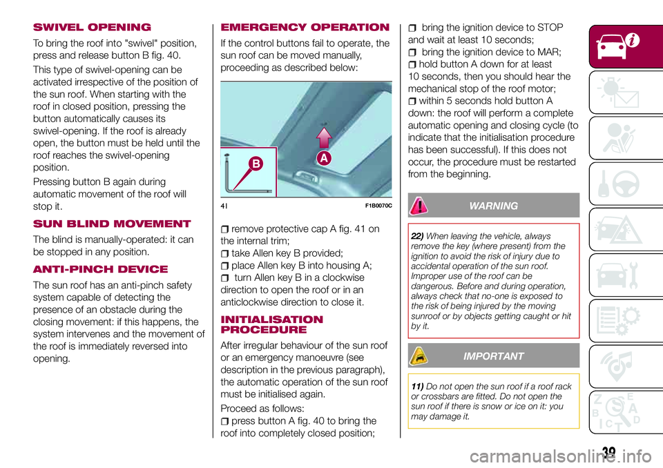
remove protective cap A fig. 41 on
the internal trim;
take Allen key B provided;
place Allen key B into housing A;
turn Allen key B in a clockwise
direction to open the roof or in an
anticlockwise direction to close it.
INITIALISATION
PROCEDURE
After irregular behaviour of the sun roof
or an emergency manoeuvre (see
description in the previous paragraph),
the automatic operation of the sun roof
must be initialised again.
Proceed as follows:
press button A fig. 40 to bring the
roof into completely closed position;
bring the ignition device to STOP
and wait at least 10 seconds;
bring the ignition device to MAR;
hold button A down for at least
10 seconds, then you should hear the
mechanical stop of the roof motor;
within 5 seconds hold button A
down: the roof will perform a complete
automatic opening and closing cycle (to
indicate that the initialisation procedure
has been successful). If this does not
occur, the procedure must be restarted
from the beginning.
WARNING
22)When leaving the vehicle, always
remove the key (where present) from the
ignition to avoid the risk of injury due to
accidental operation of the sun roof.
Improper use of the roof can be
dangerous. Before and during operation,
always check that no-one is exposed to
the risk of being injured by the moving
sunroof or by objects getting caught or hit
by it.
IMPORTANT
11)Do not open the sun roof if a roof rack
or crossbars are fitted. Do not open the
sun roof if there is snow or ice on it: you
may damage it.
41F1B0070C
39
Page 48 of 284
DISPLAY
DESCRIPTION
The vehicle is equipped with a display
that can show useful information to the
driver while driving.
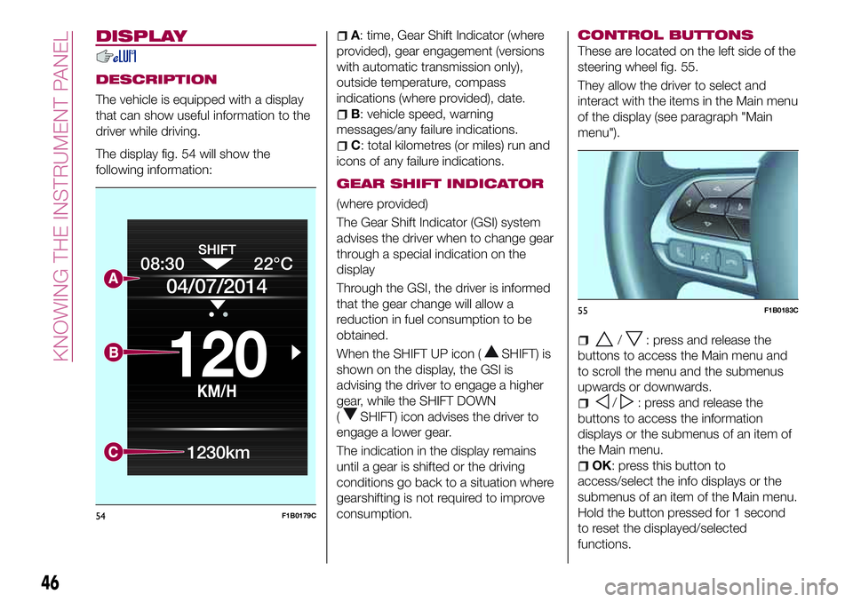
The display fig. 54 will show the
following information:
A: time, Gear Shift Indicator (where
provided), gear engagement (versions
with automatic transmission only),
outside temperature, compass
indications (where provided), date.
B: vehicle speed, warning
messages/any failure indications.
C: total kilometres (or miles) run and
icons of any failure indications.
GEAR SHIFT INDICATOR
(where provided)
The Gear Shift Indicator (GSI) system
advises the driver when to change gear
through a special indication on the
display
Through the GSI, the driver is informed
that the gear change will allow a
reduction in fuel consumption to be
obtained.
When the SHIFT UP icon (
SHIFT) is
shown on the display, the GSI is
advising the driver to engage a higher
gear, while the SHIFT DOWN
(
SHIFT) icon advises the driver to
engage a lower gear.
The indication in the display remains
until a gear is shifted or the driving
conditions go back to a situation where
gearshifting is not required to improve
consumption.
CONTROL BUTTONS
These are located on the left side of the
steering wheel fig. 55.
They allow the driver to select and
interact with the items in the Main menu
of the display (see paragraph "Main
menu").
/: press and release the
buttons to access the Main menu and
to scroll the menu and the submenus
upwards or downwards.
/: press and release the
buttons to access the information
displays or the submenus of an item of
the Main menu.
OK: press this button to
access/select the info displays or the
submenus of an item of the Main menu.
Hold the button pressed for 1 second
to reset the displayed/selected
functions.
08:30
KM/H
120
22°C
04/07/2014
1230km
54F1B0179C
55F1B0183C
46
KNOWING THE INSTRUMENT PANEL