stop start FIAT 500X 2022 Owners Manual
[x] Cancel search | Manufacturer: FIAT, Model Year: 2022, Model line: 500X, Model: FIAT 500X 2022Pages: 312, PDF Size: 13.26 MB
Page 5 of 312
3
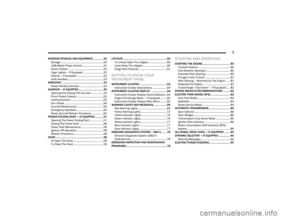
INTERIOR STORAGE AND EQUIPMENT ............... 50 Storage..............................................................50
USB/Media Player Control ...............................51
Power Outlets ..................................................52
Cigar Lighter — If Equipped .............................52
Ashtray — If Equipped ......................................52
Grab Handles....................................................53
WINDOWS............................................................... 53
Power Window Controls ...................................53
SUNROOF — IF EQUIPPED .................................... 55
Opening And Closing The Sunroof...................55
Pinch Protect Feature ......................................55
Venting Sunroof ................................................55
Sun Shade ........................................................56
Sunroof Maintenance ......................................56
Emergency Operation.......................................56
Power Sunroof Relearn Procedure..................56
POWER FOLDING ROOF — IF EQUIPPED ............ 57
Opening The Power Folding Roof ....................57
Closing The Power Roof ...................................58
Power Roof Maintenance ................................58
Ignition Off Operation .......................................58
Relearn Procedure ...........................................58
HOOD ...................................................................... 58
To Open The Hood ............................................58
To Close The Hood ...........................................59 LIFTGATE ................................................................. 60
To Unlock/Open The Liftgate...........................60
Lock/Close The Liftgate ...................................60
Cargo Area Features ........................................61
GETTING TO KNOW YOUR
INSTRUMENT PANEL
INSTRUMENT CLUSTER .........................................63
Instrument Cluster Descriptions .....................64
INSTRUMENT CLUSTER DISPLAY .......................64
Instrument Cluster Display Control Buttons ...64
Engine Oil Change Reset — If Equipped .........65
Instrument Cluster Display Main Menu ..........65
WARNING LIGHTS AND MESSAGES ....................69
Red Warning Lights ..........................................69
Yellow Warning Lights ......................................72
Yellow Indicator Lights .....................................76
Green Indicator Lights .....................................76
White Indicator Lights ......................................77
Blue Indicator Lights ........................................77
Gray Indicator Lights ........................................77
ONBOARD DIAGNOSTIC SYSTEM — OBD II.........78
Onboard Diagnostic System (OBD II)
Cybersecurity ....................................................78
EMISSIONS INSPECTION AND MAINTENANCE
PROGRAMS.............................................................78
STARTING AND OPERATING
STARTING THE ENGINE ......................................... 80
Tip Start Feature ............................................. 80
Cold Weather Operation .................................. 80
Extended Park Starting ....................................80
If Engine Fails To Start ....................................81
After Starting — Warming Up The Engine ....... 81
Stopping The Engine ........................................ 81
Turbocharger “Cool Down” — If Equipped ...... 82
ENGINE BREAK-IN RECOMMENDATIONS .......... 82
ELECTRIC PARK BRAKE (EPB) ............................. 82
Auto Park Brake ............................................... 84
SafeHold ........................................................... 84
Brake Service Mode......................................... 84
AUTOMATIC TRANSMISSION .............................. 85
Gear Selector.................................................... 86
Gear Ranges ..................................................... 86
Transmission Limp Home Mode ..................... 89
Ignition Park Interlock...................................... 89
Brake Transmission Shift Interlock (BTSI)
System ..............................................................89
ALL-WHEEL DRIVE (AWD) — IF EQUIPPED ........ 90
DYNAMIC SELECTOR — IF EQUIPPED ................. 90
Warning Messages........................................... 90
ELECTRIC POWER STEERING .............................. 90
22_FD_OM_EN_USC_t.book Page 3
Page 6 of 312

4
STOP/START SYSTEM ........................................... 91Automatic Mode ...............................................91
Possible Reasons The Engine Does Not
Autostop ............................................................91
To Start The Engine While In Autostop
Mode .................................................................92
To Manually Turn Off The Stop/Start
System ..............................................................92
To Manually Turn On The Stop/Start
System ..............................................................92
System Malfunction .........................................92
CRUISE CONTROL SYSTEMS — IF EQUIPPED..... 93
Cruise Control ...................................................93
Adaptive Cruise Control (ACC) .........................94
FRONT/REAR PARK ASSIST — IF EQUIPPED ... 102
Park Assist Sensors....................................... 103
Park Assist Warning Display ......................... 103Park Assist Display ........................................ 103
Enabling And Disabling Park Assist.............. 106
Service The Park Assist System ................... 106
Cleaning The Park Assist System ................. 106Park Assist System Usage Precautions ....... 106
LANESENSE — IF EQUIPPED ............................. 108
LaneSense Operation ................................... 108Turning LaneSense On Or Off ....................... 108
LaneSense Warning Message ...................... 108Changing LaneSense Status ........................ 110
PARKVIEW REAR BACK UP CAMERA .............. 110
REFUELING THE VEHICLE .................................. 111
VEHICLE LOADING .............................................. 112
Certification Label ......................................... 112 TRAILER TOWING ................................................ 113
Common Towing Definitions......................... 113
Trailer Hitch Classification ............................ 115
Trailer Towing Weights (Maximum Trailer
Weight Ratings) ............................................. 115Trailer And Tongue Weight............................ 116
Towing Requirements .................................. 116
Towing Tips .................................................... 118
RECREATIONAL TOWING (BEHIND
MOTORHOME) ..................................................... 119
Towing This Vehicle Behind Another
Vehicle ........................................................... 119
DRIVING TIPS ....................................................... 119
Driving On Slippery Surfaces ........................ 119
Driving Through Water ................................. 120
MULTIMEDIA
UCONNECT SYSTEMS ........................................ 122
CYBERSECURITY ................................................ 122
UCONNECT SETTINGS ........................................ 123Customer Programmable Features.............. 123
UCONNECT INTRODUCTION ............................... 138
System Overview .......................................... 138
Drag & Drop Menu Bar ................................. 140
Safety And General Information ................... 140
UCONNECT MODES ............................................. 141
Steering Wheel Audio Controls .................... 141
Radio Mode .................................................. 142
Media Mode .................................................. 150
Phone Mode ................................................. 152 ANDROID AUTO™ & APPLE CARPLAY® —
IF EQUIPPED ......................................................... 162
Android Auto™
S
........................................ 162
Apple CarPlay® ............................................. 164 Android Auto™ And Apple CarPlay® Tips
And Tricks ...................................................... 166
NAVIGATION MODE — IF EQUIPPED .................. 166
Navigation Main Menu ................................. 166
Navigating A Route........................................ 168
Search............................................................ 168
Current Route ................................................ 169
My Places....................................................... 171Parking ........................................................... 171
Gas Stations .................................................. 172Settings .......................................................... 172
RADIO OPERATION AND MOBILE PHONES...... 173
Regulatory And Safety Information .............. 173
SAFETY
SAFETY FEATURES .............................................. 174Anti-Lock Brake System (ABS)...................... 174
Electronic Brake Control (EBC) System ....... 175
AUXILIARY DRIVING SYSTEMS .......................... 178
Blind Spot Monitoring (BSM) —
If Equipped ................................................... 178
Full Brake Control System With
Mitigation ....................................................... 182Tire Pressure Monitoring System (TPMS) .... 185
22_FD_OM_EN_USC_t.book Page 4
Page 13 of 312
11
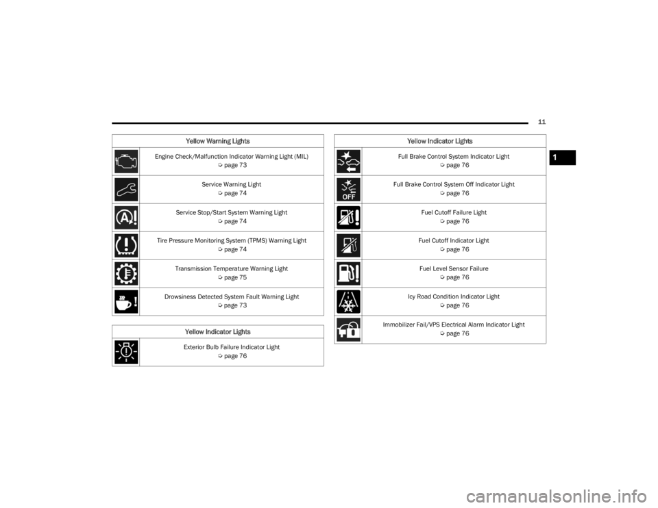
Engine Check/Malfunction Indicator Warning Light (MIL) Úpage 73
Service Warning Light Úpage 74
Service Stop/Start System Warning Light Úpage 74
Tire Pressure Monitoring System (TPMS) Warning Light Úpage 74
Transmission Temperature Warning Light Úpage 75
Drowsiness Detected System Fault Warning Light Úpage 73
Yellow Indicator Lights
Exterior Bulb Failure Indicator Light
Úpage 76
Yellow Warning Lights
Full Brake Control System Indicator Light
Úpage 76
Full Brake Control System Off Indicator Light Úpage 76
Fuel Cutoff Failure Light Úpage 76
Fuel Cutoff Indicator Light Úpage 76
Fuel Level Sensor Failure Úpage 76
Icy Road Condition Indicator Light Úpage 76
Immobilizer Fail/VPS Electrical Alarm Indicator Light Úpage 76
Yellow Indicator Lights
1
22_FD_OM_EN_USC_t.book Page 11
Page 14 of 312
12
Green Indicator Lights
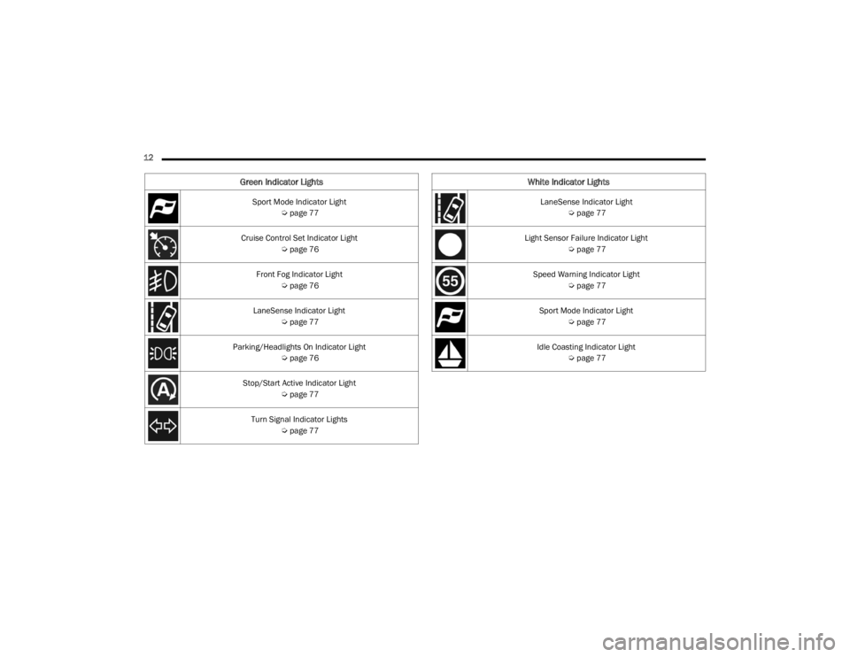
Sport Mode Indicator Light Úpage 77
Cruise Control Set Indicator Light Úpage 76
Front Fog Indicator Light Úpage 76
LaneSense Indicator Light Úpage 77
Parking/Headlights On Indicator Light Úpage 76
Stop/Start Active Indicator Light Úpage 77
Turn Signal Indicator Lights Úpage 77
White Indicator Lights
LaneSense Indicator Light
Úpage 77
Light Sensor Failure Indicator Light Úpage 77
Speed Warning Indicator Light Úpage 77
Sport Mode Indicator Light Úpage 77
Idle Coasting Indicator Light Úpage 77
22_FD_OM_EN_USC_t.book Page 12
Page 18 of 312
16GETTING TO KNOW YOUR VEHICLE
(Continued)
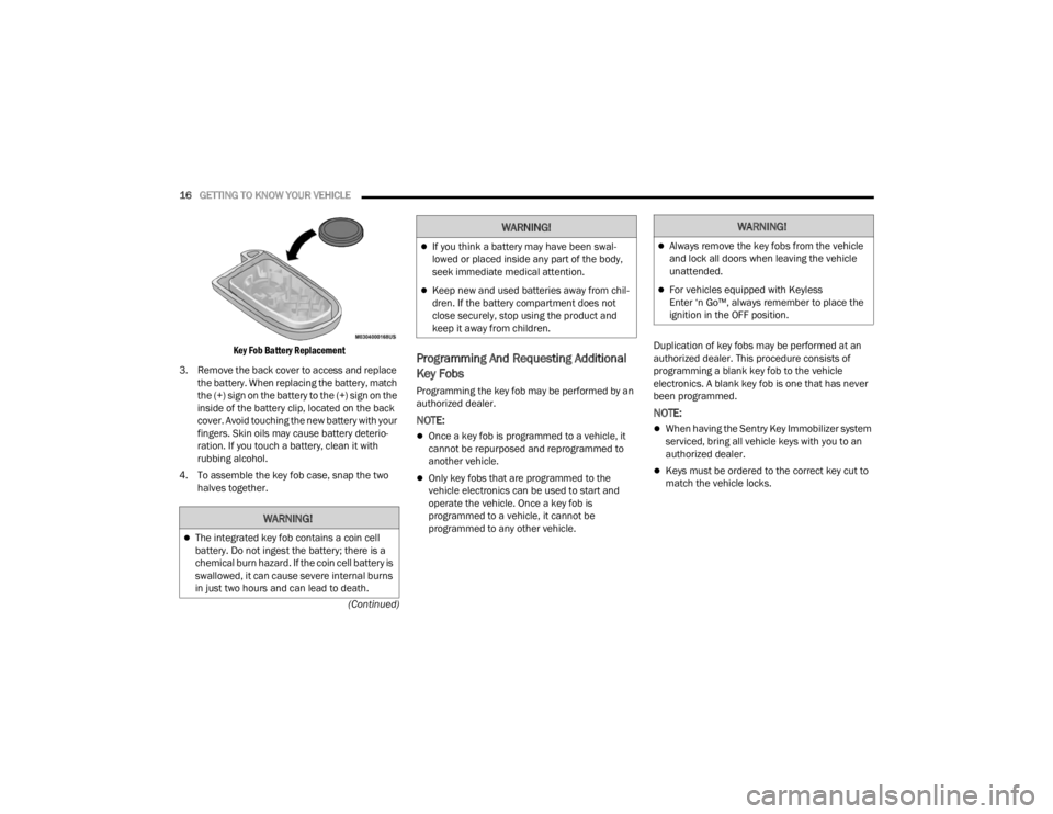
Key Fob Battery Replacement
3. Remove the back cover to access and replace the battery. When replacing the battery, match
the (+) sign on the battery to the (+) sign on the
inside of the battery clip, located on the back
cover. Avoid touching the new battery with your
fingers. Skin oils may cause battery deterio -
ration. If you touch a battery, clean it with
rubbing alcohol.
4. To assemble the key fob case, snap the two halves together.
Programming And Requesting Additional
Key Fobs
Programming the key fob may be performed by an
authorized dealer.
NOTE:
Once a key fob is programmed to a vehicle, it
cannot be repurposed and reprogrammed to
another vehicle.
Only key fobs that are programmed to the
vehicle electronics can be used to start and
operate the vehicle. Once a key fob is
programmed to a vehicle, it cannot be
programmed to any other vehicle. Duplication of key fobs may be performed at an
authorized dealer. This procedure consists of
programming a blank key fob to the vehicle
electronics. A blank key fob is one that has never
been programmed.
NOTE:
When having the Sentry Key Immobilizer system
serviced, bring all vehicle keys with you to an
authorized dealer.
Keys must be ordered to the correct key cut to
match the vehicle locks.
WARNING!
The integrated key fob contains a coin cell
battery. Do not ingest the battery; there is a
chemical burn hazard. If the coin cell battery is
swallowed, it can cause severe internal burns
in just two hours and can lead to death.
If you think a battery may have been swal-
lowed or placed inside any part of the body,
seek immediate medical attention.
Keep new and used batteries away from chil
-
dren. If the battery compartment does not
close securely, stop using the product and
keep it away from children.
WARNING!WARNING!
Always remove the key fobs from the vehicle
and lock all doors when leaving the vehicle
unattended.
For vehicles equipped with Keyless
Enter ‘n Go™, always remember to place the
ignition in the OFF position.
22_FD_OM_EN_USC_t.book Page 16
Page 19 of 312
GETTING TO KNOW YOUR VEHICLE17
SENTRY KEY
The Sentry Key Immobilizer system prevents
unauthorized vehicle operation by disabling the
engine. The system does not need to be armed or
activated. Operation is automatic, regardless of
whether the vehicle is locked or unlocked.
The system uses a key fob, keyless push button
ignition and a Radio Frequency (RF) receiver to
prevent unauthorized vehicle operation. Therefore,
only key fobs that are programmed to the vehicle
can be used to start and operate the vehicle. The
system will shut the engine off in two seconds if an
incorrect key fob is used to start the engine.
After placing the ignition switch in the ON/RUN
position, the Vehicle Security Light will turn on for
three seconds for a bulb check. If the light remains
on after the bulb check, it indicates that there is a
problem with the electronics. In addition, if the light
begins to flash after the bulb check, it indicates
that someone used an invalid key fob to start the
engine. Either of these conditions will result in the
engine being shut off after two seconds.
If the Vehicle Security Light turns on during normal
vehicle operation (vehicle running for longer than
10 seconds), it indicates that there is a fault in the
electronics. Should this occur, have the vehicle
serviced as soon as possible by an authorized
dealer. All of the key fobs provided with your new vehicle
have been programmed to the vehicle electronics
Ú
page 297.
IGNITION SWITCH
KEYLESS ENTER ‘N GO™ IGNITION
This feature allows the driver to operate the
ignition switch with the push of a button as long as
the key fob is in the passenger compartment.
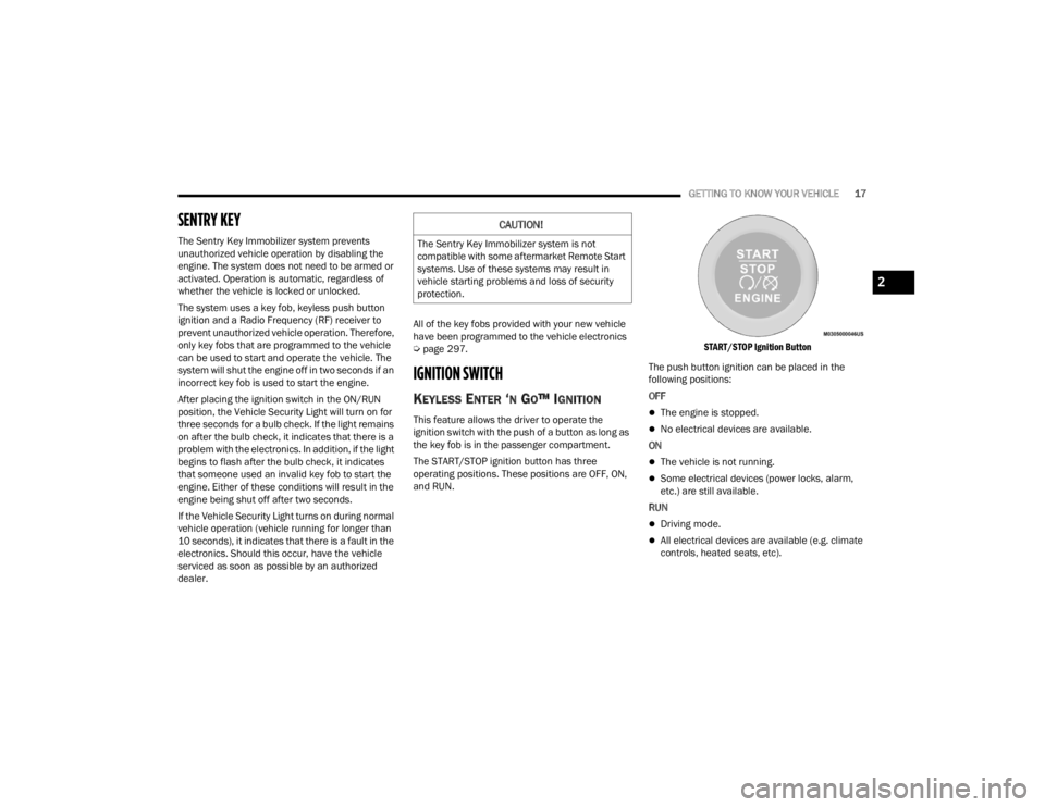
The START/STOP ignition button has three
operating positions. These positions are OFF, ON,
and RUN.
START/STOP Ignition Button
The push button ignition can be placed in the
following positions:
OFFThe engine is stopped.
No electrical devices are available.
ON
The vehicle is not running.
Some electrical devices (power locks, alarm,
etc.) are still available.
RUN
Driving mode.
All electrical devices are available (e.g. climate
controls, heated seats, etc).
CAUTION!
The Sentry Key Immobilizer system is not
compatible with some aftermarket Remote Start
systems. Use of these systems may result in
vehicle starting problems and loss of security
protection.
2
22_FD_OM_EN_USC_t.book Page 17
Page 20 of 312
18GETTING TO KNOW YOUR VEHICLE
(Continued)
NOTE:The vehicle will not start if the key fob is located
inside the cargo area and the liftgate is opened.
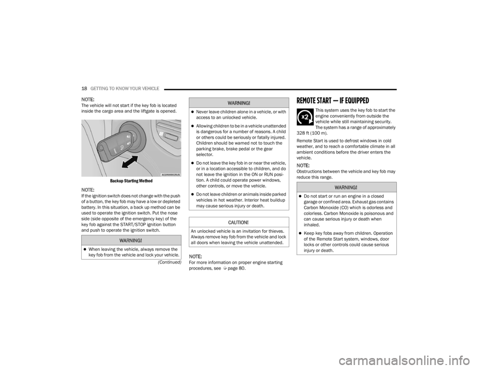
Backup Starting Method
NOTE:If the ignition switch does not change with the push
of a button, the key fob may have a low or depleted
battery. In this situation, a back up method can be
used to operate the ignition switch. Put the nose
side (side opposite of the emergency key) of the
key fob against the START/STOP ignition button
and push to operate the ignition switch.
NOTE:For more information on proper engine starting
procedures, see Ú page 80.
REMOTE START — IF EQUIPPED
This system uses the key fob to start the
engine conveniently from outside the
vehicle while still maintaining security.
The system has a range of approximately
328 ft (100 m).
Remote Start is used to defrost windows in cold
weather, and to reach a comfortable climate in all
ambient conditions before the driver enters the
vehicle.
NOTE:Obstructions between the vehicle and key fob may
reduce this range.
WARNING!
When leaving the vehicle, always remove the
key fob from the vehicle and lock your vehicle.
Never leave children alone in a vehicle, or with
access to an unlocked vehicle.
Allowing children to be in a vehicle unattended
is dangerous for a number of reasons. A child
or others could be seriously or fatally injured.
Children should be warned not to touch the
parking brake, brake pedal or the gear
selector.
Do not leave the key fob in or near the vehicle,
or in a location accessible to children, and do
not leave the ignition in the ON or RUN posi -
tion. A child could operate power windows,
other controls, or move the vehicle.
Do not leave children or animals inside parked
vehicles in hot weather. Interior heat buildup
may cause serious injury or death.
CAUTION!
An unlocked vehicle is an invitation for thieves.
Always remove key fob from the vehicle and lock
all doors when leaving the vehicle unattended.
WARNING!
WARNING!
Do not start or run an engine in a closed
garage or confined area. Exhaust gas contains
Carbon Monoxide (CO) which is odorless and
colorless. Carbon Monoxide is poisonous and
can cause serious injury or death when
inhaled.
Keep key fobs away from children. Operation
of the Remote Start system, windows, door
locks or other controls could cause serious
injury or death.
22_FD_OM_EN_USC_t.book Page 18
Page 21 of 312
GETTING TO KNOW YOUR VEHICLE19
HOW TO USE REMOTE START
Push and release the Remote Start button on the
key fob twice within five seconds. The vehicle
doors will lock, the parking lights will flash, and the
horn will chirp twice (if programmed). Then the
engine will start and the vehicle will remain in the
Remote Start mode for a 15 minute cycle. Pushing
the Remote Start button a third time shuts the
engine off.
With Remote Start, the engine will only run for
15 minutes.
If an engine fault is present or fuel level is low,
the vehicle will start and then shut down in 10
seconds.
The parking lights will turn on and remain on
during Remote Start mode.
For security, power window and power sunroof
operation (if equipped) are disabled when the
vehicle is in the Remote Start mode.
The ignition must be placed in the ON/RUN posi -
tion before the Remote Start sequence can be
repeated for a third cycle. All of the following conditions must be met before
the engine will remote start:
Gear Selector in PARK
Doors closed
Hood closed
Liftgate closed
Hazard switch off
Brake switch inactive (brake pedal not pressed)
Battery at an acceptable charge level
PANIC button not pushed
System not disabled from previous Remote
Start event
Vehicle Security Light flashing
Ignition in OFF position
Fuel level meets minimum requirement
Vehicle Security system is not signaling an intru
-
sion
Malfunction Indicator Light (MIL) is not illumi -
nated
TO EXIT REMOTE START MODE
To drive the vehicle after starting the Remote Start
system, push and release the START/STOP ignition
button while pressing the brake pedal prior to the
end of the 15 minute cycle.
The Remote Start system will turn the engine off
with another push and release of the Remote Start
button on the key fob, or if the engine is allowed to
run for the entire 15 minute cycle. Once the
ignition is placed in the ON/RUN position, the
climate controls will resume the previously set
operations (temperature, blower control, etc.).
NOTE:
For vehicles equipped with the Keyless
Enter ‘n Go™ — Passive Entry feature, the
WARNING!
Do not start or run an engine in a closed
garage or confined area. Exhaust gas contains
Carbon Monoxide (CO) which is odorless and
colorless. Carbon Monoxide is poisonous and
can cause serious injury or death when
inhaled.
Keep key fobs away from children. Operation
of the Remote Start system, windows, door
locks or other controls could cause serious
injury or death.
2
22_FD_OM_EN_USC_t.book Page 19
Page 22 of 312
20GETTING TO KNOW YOUR VEHICLE
message “Remote Start Active — Push Start
Button” will display in the instrument cluster
display until you push the START/STOP ignition
button.
To avoid unintentional shutdowns, the system
will disable for two seconds after receiving a
valid Remote Start request.
REMOTE START FRONT DEFROST
A
CTIVATION — IF EQUIPPED
When Remote Start is active, and the outside
ambient temperature is 40°F (4.5°C) or below, the
system will automatically activate front defrost for
15 minutes or less. The timing is dependent on the
ambient temperature. Once the timer expires, the
system will automatically adjust the settings
depending on ambient conditions. See “Remote
Start Comfort Systems — If Equipped” in the next
section for detailed operation.
REMOTE START COMFORT SYSTEMS —
I
F EQUIPPED
When Remote Start is activated, the front and rear
defrost will automatically turn on in cold weather.
The heated steering wheel and driver heated seat
feature will turn on if selected in the comfort menu
screen within Uconnect Settings Úpage 123. The
vehicle will adjust the climate control settings
depending on the outside ambient temperature. Automatic Temperature Control (ATC) —
If Equipped
The climate controls will be automatically adjusted
to the optimal temperature and mode settings
depending on the outside ambient temperature.
This will occur until the ignition is placed in the ON/
RUN position where the climate controls will
resume their previous settings.
Manual Temperature Control (MTC) — If Equipped
In ambient temperatures at 40°F (4.5°C) or
below, the climate settings will default to
maximum heat, with fresh air entering the
cabin. If the front defrost timer expires, the
vehicle will enter Mix Mode.
In ambient temperatures from 40°F (4.5°C) to
78°F (26°C), the climate settings will be based
on the last settings selected by the driver.
In ambient temperatures at 78°F (26°C) or
above, the climate settings will default to MAX
A/C, Bi-Level Mode, with Recirculation on.
For more information on ATC, MTC, and climate
control settings, see Ú page 43.
NOTE:These features will stay on through the duration of
Remote Start until the ignition is placed in the ON/
RUN position. The climate control settings will
change if manually adjusted by the driver while the
vehicle is in Remote Start mode, and exit auto -matic override. This includes the OFF button on the
climate controls, which will turn the system off.
REMOTE START WINDSHIELD WIPER
D
E–ICER AND REAR DEFROST
A
CTIVATION — IF EQUIPPED
When Remote Start is active and the outside
ambient temperature is less than 40°F (4.4°C),
the Windshield Wiper De-Icer will activate. Exiting
Remote Start will resume its previous operation. If
the Windshield Wiper De-Icer was active, the timer
and operation will continue.
REMOTE START CANCEL MESSAGE —
I
F EQUIPPED
The following messages will display in the
instrument cluster if the vehicle fails to remote
start or exits Remote Start prematurely:
Remote Start Cancelled — Door Open
Remote Start Cancelled — Hood Open
Remote Start Cancelled — Fuel Low
Remote Start Cancelled — Liftgate Open
Remote Start Cancelled — Too Cold
Remote Start Cancelled — Time Expired
Remote Start Disabled — Start Vehicle To Reset
The message will stay active until the ignition is
placed in the ON/RUN position.
22_FD_OM_EN_USC_t.book Page 20
Page 31 of 312
GETTING TO KNOW YOUR VEHICLE29
(Continued)
Adjusting The Seat Up Or Down
The height of the seats can be adjusted up or down
by using the power seat switch. The seat will move
in the direction of the switch. Release the switch
when the desired position is reached.
Tilting The Seat Up Or Down
The angle of the seat cushion can be adjusted up
or down using the power seat switch. The front of
the seat cushion will move in the direction of the
switch. Release the switch when the desired
position has been reached.
Reclining The Seatback
Push the seat recliner switch forward or rearward.
The seatback will move in the direction of the
switch. Release the switch when the desired
position has been reached.
Power Lumbar — If Equipped
Vehicles equipped with power driver or passenger
seats may also be equipped with power lumbar.
The power lumbar switch is located on the
outboard side of the power seat. Push the switch
forward to increase the lumbar support. Push the
switch rearward to decrease the lumbar support.
Pushing upward or downward on the switch will
raise and lower the position of the support.
HEATED SEATS — IF EQUIPPED
The heated seat switches are located on
the instrument panel.
You can choose between two heating levels:
Push the heated seat button once to turn the HI
setting on.
Push the heated seat button a second time to
turn the LO setting on.
Push the heated seat button a third time to turn
the heating elements off.
If the HI-level setting is selected, the system will
automatically switch to LO-level after
approximately 145 minutes of continuous
operation. At that time, the display will change
from HI to LO, indicating the change. The LO-level
setting will turn off automatically after
approximately 60 minutes.
NOTE:
The timing may vary based on environmental
temperature.
The engine must be running for the heated
seats to operate.
For information on use with the Remote Start
system, see Ú page 20.
WARNING!
Adjusting a seat while driving may be
dangerous. Moving a seat while driving could
result in loss of control which could cause a
collision and serious injury or death.
Seats should be adjusted before fastening the
seat belts and while the vehicle is parked.
Serious injury or death could result from a
poorly adjusted seat belt.
Do not ride with the seatback reclined so that
the shoulder belt is no longer resting against
your chest. In a collision you could slide under
the seat belt, which could result in serious
injury or death.
CAUTION!
Do not place any article under a power seat or
impede its ability to move as it may cause
damage to the seat controls. Seat travel may
become limited if movement is stopped by an
obstruction in the seat’s path.
WARNING!
2
22_FD_OM_EN_USC_t.book Page 29