fuel pressure FIAT BARCHETTA 2003 1.G Owners Manual
[x] Cancel search | Manufacturer: FIAT, Model Year: 2003, Model line: BARCHETTA, Model: FIAT BARCHETTA 2003 1.GPages: 170, PDF Size: 3.55 MB
Page 31 of 170
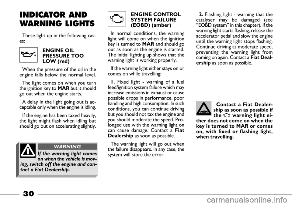
ENGINE CONTROL
SYSTEM FAILURE
(EOBD) (amber)
In normal conditions, the warning
light will come on when the ignition
key is turned to MARand should go
out as soon as the engine is started.
The initial lighting up shows that the
warning light is working properly.
If the warning light either stays on or
comes on while travelling:
1.Fixed light - warning of a fuel
feed/ignition system failure which may
increase emissions in exhaust or cause
possible drops in performance, poor
handling and high consumption. In such
conditions, you can continue driving
but you should not tax the engine and
you should moderate the speed. Pro-
longed use with the warning light on
can cause damage. Contact aFiat
Dealershipas soon as possible.
The warning light will go out when
the failure disappears. In any case, the
system will store the error. ENGINE OIL
PRESSURE TOO
LOW (red)
When the pressure of the oil in the
engine falls below the normal level.
The light comes on when you turn
the ignition key to MARbut it should
go out when the engine starts.
A delay in the light going out is ac-
ceptable only when the engine is idling.
If the engine has been taxed heavily,
the light might flash when idling but
should go out on accelerating slightly.
30
v
U
INDICATOR AND
WARNING LIGHTS
These light up in the following cas-
es:2.Flashing light - warning that the
catalyser may be damaged (see
“EOBD system” in this chapter). If the
warning light starts flashing, release the
accelerator pedal and slow the engine
until the warning light stops flashing.
Continue driving at moderate speed,
preventing the warning light from
coming on again. Contact a Fiat Deal-
ership as soon as possible.
Contact a Fiat Dealer-
ship as soon as possible if
the
Uwarning light ei-
ther does not come on when the
key is turned to MAR or comes
on, with fixed or flashing light,
when travelling.
If the warning light comes
on when the vehicle is mov-
ing, switch off the engine and con-
tact a Fiat Dealership.
WARNING
Page 66 of 170
65
A catalytic converter
that does not work prop-
erly leads to the emission
of harmful gases and the conse-
quent pollution of the atmos-
phere.
Never put even the tini-
est amount of leaded
petrol into the fuel tank,
even in an emergency. You would
damage the catalytic converter
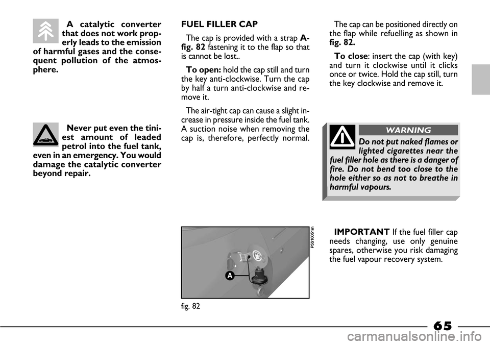
beyond repair.FUEL FILLER CAP
The cap is provided with a strap A-
fig. 82fastening it to the flap so that
is cannot be lost..
To open:hold the cap still and turn
the key anti-clockwise. Turn the cap
by half a turn anti-clockwise and re-
move it.
The air-tight cap can cause a slight in-
crease in pressure inside the fuel tank.
A suction noise when removing the
cap is, therefore, perfectly normal.The cap can be positioned directly on
the flap while refuelling as shown in
fig. 82.
To close: insert the cap (with key)
and turn it clockwise until it clicks
once or twice. Hold the cap still, turn
the key clockwise and remove it.
IMPORTANT If the fuel filler cap
needs changing, use only genuine
spares, otherwise you risk damaging
the fuel vapour recovery system.
fig. 82
P5S10051m
Do not put naked flames or
lighted cigarettes near the
fuel filler hole as there is a danger of
fire. Do not bend too close to the
hole either so as not to breathe in
harmful vapours.
WARNING
Page 77 of 170
76
Here are some suggestions which
may help you to keep the running
costs of your vehicle down and low-
er the amount of toxic emissions re-
leased into the atmosphere.
GENERAL
CONSIDERATIONS
Car maintenance
The overall state of the car is an im-
portant factor which has a marked in-
fluence over fuel consumption and dri-
ving comfort and on the life span of
your car. For this reason care should
be taken to maintain your car by car-
rying out the necessary checks and
regulations in accordance with the
specifications given in the Scheduled
Maintenance Programme (see sec-
tions... spark plugs, idle, air filter, tim-
ing).
CONTAINING RUNNING COSTS
AND POLLUTION
Tyres
Tyres should be checked at least
every four weeks: if the pressure is
too low fuel consumption increases as
the resistance to the rolling movement
of the tyre is greater. In this state, tyre
wear is increased and car handling suf-
fers which will affect safety.
Unnecessary loads
Do not travel with too much luggage
stowed in the boot. The weight of the
vehicle (especially when driving in
town) and its trim greatly affects con-
sumption and stability. To get the most out of ABS:
– During emergency stops or when
grip conditions are poor, you will feel
a slight pulsation on the brake pedal.
This is the sign that the ABS is in ac-
tion. Do not release the brake pedal
but continue to press so as not to in-
terrupt the braking action.
– ABS prevents the wheels from
locking but it does not increase actu-
al grip conditions between tyre and
road. Therefore, even if your car is fit-
ted with ABS, respect the safety dis-
tance from the car in front of you and
keep your speed down when driving
into bends.
– ABS serves to increase the con-
trollability of the car, not to enable you
to go faster.
Page 114 of 170
113
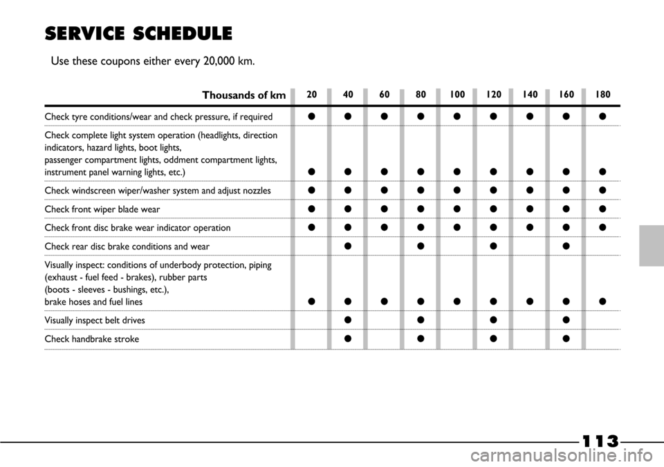
SERVICE SCHEDULE
Use these coupons either every 20,000 km.
Thousands of km20 40 60 80 100 120 140 160 180
Check tyre conditions/wear and check pressure, if required
Check complete light system operation (headlights, direction
indicators, hazard lights, boot lights,
passenger compartment lights, oddment compartment lights,
instrument panel warning lights, etc.)
Check windscreen wiper/washer system and adjust nozzles
Check front wiper blade wear
Check front disc brake wear indicator operation
Check rear disc brake conditions and wear
Visually inspect: conditions of underbody protection, piping
(exhaust - fuel feed - brakes), rubber parts
(boots - sleeves - bushings, etc.),
brake hoses and fuel lines
Visually inspect belt drives
Check handbrake stroke
ççççççççç
ççççççççç
ççççççççç
ççççççççç
ççççççççç
çççç
ççççççççç
çççç
çççç
Page 116 of 170
115
ANNUAL
INSPECTION
SCHEDULE
The following annual inspection
schedule is required for cars travelling
less than 20,000 km a year (e.g. ap-
proximately 10,000 km). The schedule
includes the following operations:
– Check tyre condition and wear and
adjust pressure, if required (including
spare-saver spare wheel).
– Check operation of lights (head-
lights, direction indicators, hazard
lights, boot light, passenger compart-
ment ceiling light, glove compartment
light, instrument panel lights, etc.).
– Check windscreen wiper/washer
and adjust nozzles.
– Check position wear of windscreen
window wiper blades.
ADDITIONAL
OPERATIONS
Every 1,000 kmor before long
trips, check and top up as necessary:
– coolant level
– brake fluid level
– power steering fluid level
– electrolyte level
– windscreen washer liquid level
– tyre condition and pressure.
We advise you to use FL Selenia
products, which have been designed
and produced expressly for the Fiat
vehicles (see the table “Capacities” giv-
en in the “Technical specifications”
section).
Every 3,000 km check and top up
as necessary: engine oil level. – Check rear brake pad conditions
and wear.
– Inspect conditions of. engine, gear-
box, transmission, piping (exhaust - fu-
el feed - brakes), rubber parts (boots
- sleeves - bushings - etc.), brake and
fuel line hoses.
– Check battery charge status.
– Check conditions of various con-
trol belts.
– Check and top up fluid levels (en-
gine coolant, brakes, windscreen
washer, battery, etc.).
– Change engine oil.
– Replace engine oil filter.
– Replace pollen filter (where fitted).
Page 136 of 170
135
TECHNICAL SPECIFICATIONS
Motor and engineering enthusiasts as well as those
“in the trade” will probably start reading from this point
in the manual. This, in fact, is where a section jam-
packed with facts, figures, formulae, measurements and
tables begins. In a sense it is the Fiat barchetta’s iden-
tity card. A document that introduces the car and ex-
plains in technical jargon all the features that go together
to make the Fiat barchetta a model designed to give you
superlative driving satisfaction.IDENTIFICATION DATA ................................................ 136
ENGINE CODE - BODY VERSION .............................. 137
ENGINE ................................................................................. 137
TRANSMISSION ................................................................. 139
BRAKES ................................................................................. 139
SUSPENSIONS .................................................................... 140
STEERING ............................................................................. 140
WHEEL GEOMETRY ......................................................... 140
PERFORMANCE ................................................................. 140
WHEELS ................................................................................ 141
DIMENSIONS ...................................................................... 142
WEIGHTS ............................................................................. 143
CAPACITIES ........................................................................ 144
FLUIDS AND LUBRICANTS ........................................... 145
FUEL CONSUMPTION .................................................... 147
CO
2EMISSIONS ................................................................. 147
TYRES PRESSURE ............................................................... 148
Page 139 of 170
138
FUEL SUPPLY/IGNITION
Integrated electronic injection and ig-
nition system: a single electronic con-
trol unit controls both functions. It
processes both the time the injection
lasts (for fuel metering) and the igni-
tion’s advance angle.
Type: Sequential in phase Multipoint
Air cleaner: dry-type with paper fil-
ter element; thermostatically con-
trolled intake.
Petrol pump: in-tank.
Injection pressure: 3 bar
Method of measuring the amount of
aspirated air by directly measuring the
maximum rate of flow with a hot wire
air flow meter.
“Closed loop” petrol metering (in-
formation about combustion provid-
ed by the Lambda sensor).Firing order: 1-3-4-2
Spark plugs:
– Champion RC10YCC
– NGK BKR6EZLUBRICATION
Forced-fed with gear pump with
pressure relief valve incorporated.
Oil purification by means of full-flow-
cartridge filter.
COOLING
Cooling system with radiator, cen-
trifugal pump and expansion tank.
“Controlled” by-pass type thermo-
stat on the secondary circuit for the
recirculation of water from the engine
to the radiator.
Electric fan for radiator cooling with
thermostatically-controlled on/off
switch on the radiator.
Modifications or repairs to
the fuel feed system that
are not carried out properly or do
not take the system’s technical
specifications into account can
cause malfunctions with the risk of
fire.
WARNING