maintenance reset FIAT CROMA 2006 2.G Owners Manual
[x] Cancel search | Manufacturer: FIAT, Model Year: 2006, Model line: CROMA, Model: FIAT CROMA 2006 2.GPages: 240, PDF Size: 7.41 MB
Page 9 of 240
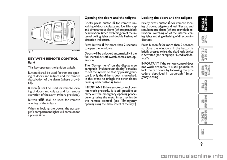
KEY WITH REMOTE CONTROL
fig. 6
This key operates the ignition switch.
Button Ëshall be used for remote open-
ing of doors and tailgate and for remote
deactivation of the alarm (where provid-
ed).
Button Áshall be used for remote lock-
ing of doors and tailgate and for remote
activation of the alarm (where provided).
Button Rshall be used for remote
opening of the tailgate.
When unlocking the doors, the passen-
ger’s compartment lights will come on for
a preset time.
fig. 6F0L0100m
9
SAFETY
DEVICES
CORRECT USE
OF THE CAR
WARNING
LIGHTS AND
MESSAGES
IN AN
EMERGENCY
CAR
MAINTENANCE
TECHNICAL
SPECIFICATIONS
INDEX
DASHBOARD
AND CONTROLS
Opening the doors and the tailgate
Briefly press button Ëfor remote un-
locking of doors, tailgate and fuel filler cap
and simultaneous alarm (where provided)
deactivation, timed switching on of the in-
ternal ceiling lights and double flashing of
direction indicators.
Press button Ëfor more than 2 seconds
to open the windows.
Doors will be unlocked automatically if the
fuel inertial cut-off switch comes into op-
eration.
The “Set-up menu” on the display (see
paragraph “Multifunction display”) enables
to set the system so that by pressing but-
ton Ë, only the driver’s door is unlocked.
In this event, to unlock the other doors
press quickly button Ëtwice.
IMPORTANT If the remote control does
not work properly, it is still possible to
carry out the emergency opening proce-
dure by using the metal insert set inside
the remote control (see “Emergency
opening using the metal insert of the key”).Locking the doors and the tailgate
Briefly press button Áfor remote lock-
ing of doors, tailgate and fuel filler cap and
simultaneous alarm (where provided) ac-
tivation, switching off of the internal ceil-
ing lights and single flashing of direction in-
dicators.
Press button Áfor more than 2 seconds
to close the windows. If the button is
briefly pressed twice, the dead lock device
is activated (see paragraph “Dead lock de-
vice”).
IMPORTANT If the remote control does
not work properly, it is still possible to
lock the car doors by following the pro-
cedure described in paragraph “Emer-
gency closing”
001-030 Croma TRW GB 20-11-2006 14:58 Pagina 9
Page 28 of 240

28
SAFETY
DEVICES
CORRECT USE
OF THE CAR
WARNING
LIGHTS AND
MESSAGES
IN AN
EMERGENCY
CAR
MAINTENANCE
TECHNICAL
SPECIFICATIONS
INDEX
DASHBOARD
AND CONTROLS
at Dealership to carry out any service op-
eration provided by the “Service sched-
ule” or “Annual inspection plan”, and to
reset the display.
Exit Menu
This is the last function that closes the cir-
cular setting cycle listed in the initial menu
screen.
Briefly press button MODEto go back to
the standard screen without storing set-
tings.
Press button –to return to the first menu
option (Speed Lim.).Both functions are resettable (reset - start
of new mission).
“General Trip” displays the figures relat-
ing to:
– Range
– Trip distance
– Average consumption
– Instant consumption
– Average speed
– Travel time (driving time).
“Trip B” (only available on reconfigurable
multifunction display), displays the figures
relating to:
– Trip distance B
– Average consumption B
– Average speed B
– Travel time B (driving time).
NoteThe “Trip B” function can be ex-
cluded (see paragraph “Trip B On/Off”).
“Range” cannot be reset.TRIP COMPUTER
(where provided)
General features
The “Trip computer” is provided on cars
fitted with multifunction display or re-
configurable multifunction display. The
“Trip computer” displays information
(with ignition key at ON), relating to the
operating status of the car. This function
comprises the “General trip” concerning
the “complete mission” of the car (jour-
ney) and “Trip B”, (only available on re-
configurable multifunction display), con-
cerning the partial mission of the car; this
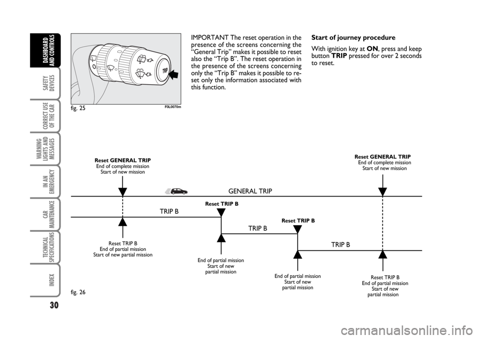
latter function(as shown in fig. 26) is “con-
tained” within the complete mission.
001-030 Croma TRW GB 20-11-2006 14:58 Pagina 28
Page 29 of 240

29
SAFETY
DEVICES
CORRECT USE
OF THE CAR
WARNING
LIGHTS AND
MESSAGES
IN AN
EMERGENCY
CAR
MAINTENANCE
TECHNICAL
SPECIFICATIONS
INDEX
DASHBOARD
AND CONTROLS
Values displayed
Range
This value shows the distance in km (or
mi) that the car can still cover before
needing fuel, assuming that driving condi-
tions are kept unvaried. The display will
show “----” in the following cases:
– value lower than 50 km (or 30 mi)
– car left parked with engine running for
long.
Trip distance
This value shows the distance covered
from the start of the new mission.
Average consumption
This value shows the average consump-
tion from the start of the new mission.
Instant consumption
This value shows instant fuel consumption
(this value is updated second by second).
If parking the car with engine on,
the display will show “----”.Average speed
This value shows the car average speed as
a function of the overall time elapsed since
the start of the new mission.
Travel time
This value shows the time elapsed since
the start of the new mission.
IMPORTANT Lacking information, Trip
computer values are displayed with “----”.
When normal operating condition is re-
set, calculation of different units will
restart regularly. Values displayed before
the failure will not be reset.TRIP button fig. 25
Button TRIP, set on the top of the right
steering column stalk, shall be used (with
ignition key at ON) to display and to re-
set the previously described values to start
a new mission:
– short push to display the different val-
ues
– long push to reset and then start a new
mission.
New mission
New mission starts after:
– “manual” resetting by the user, by press-
ing the relevant button;
– “automatic” resetting, when the “Trip dis-
tance” reaches 9999.9 km or when the
“Travel time” reaches 99.59 (99 hours and
59 minutes);
– after disconnecting/reconnecting the
battery.
001-030 Croma TRW GB 20-11-2006 14:58 Pagina 29
Page 30 of 240
30
SAFETY
DEVICES
CORRECT USE
OF THE CAR
WARNING
LIGHTS AND
MESSAGES
IN AN
EMERGENCY
CAR
MAINTENANCE
TECHNICAL
SPECIFICATIONS
INDEX
DASHBOARD
AND CONTROLS
IMPORTANT The reset operation in the
presence of the screens concerning the
“General Trip” makes it possible to reset
also the “Trip B”. The reset operation in
the presence of the screens concerning
only the “Trip B” makes it possible to re-
set only the information associated with
this function.Start of journey procedure
With ignition key at ON, press and keep
button TRIPpressed for over 2 seconds
to reset.
F0L0070mfig. 25
Reset TRIP B
End of partial mission
Start of new partial mission
End of partial mission
Start of new
partial mission
Reset TRIP B
End of partial mission
Start of new
partial mission Reset GENERAL TRIP
End of complete mission
Start of new missionReset GENERAL TRIP
End of complete mission
Start of new mission
End of partial mission
Start of new
partial mission Reset TRIP B
Reset TRIP B
TRIP B
TRIP B
TRIP B GENERAL TRIP˙
˙
˙
˙˙
˙
˙ ˙
fig. 26
001-030 Croma TRW GB 20-11-2006 14:58 Pagina 30
Page 32 of 240
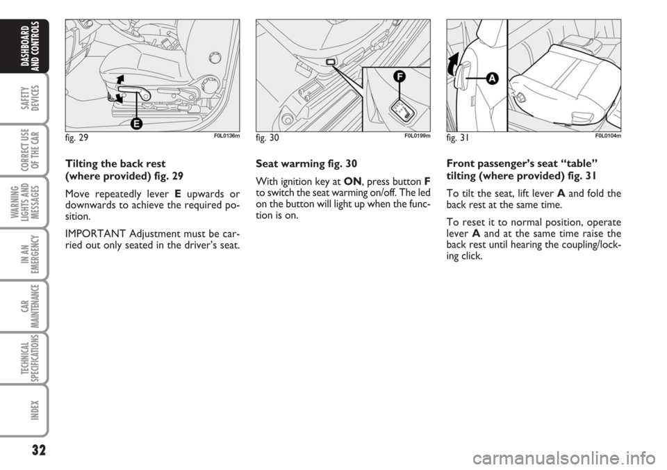
Seat warming fig. 30
With ignition key at ON, press button F
to switch the seat warming on/off. The led
on the button will light up when the func-
tion is on.
32
SAFETY
DEVICES
CORRECT USE
OF THE CAR
WARNING
LIGHTS AND
MESSAGES
IN AN
EMERGENCY
CAR
MAINTENANCE
TECHNICAL
SPECIFICATIONS
INDEX
DASHBOARD
AND CONTROLS
Tilting the back rest
(where provided) fig. 29
Move repeatedly lever Eupwards or
downwards to achieve the required po-
sition.
IMPORTANT Adjustment must be car-
ried out only seated in the driver’s seat.
fig. 29F0L0136mfig. 30F0L0199mfig. 31F0L0104m
Front passenger’s seat “table”
tilting (where provided) fig. 31
To tilt the seat, lift lever Aand fold the
back rest at the same time.
To reset it to normal position, operate
lever Aand at the same time raise the
back rest until hearing the coupling/lock-
ing click.
Page 38 of 240
38
SAFETY
DEVICES
CORRECT USE
OF THE CAR
WARNING
LIGHTS AND
MESSAGES
IN AN
EMERGENCY
CAR
MAINTENANCE
TECHNICAL
SPECIFICATIONS
INDEX
DASHBOARD
AND CONTROLS
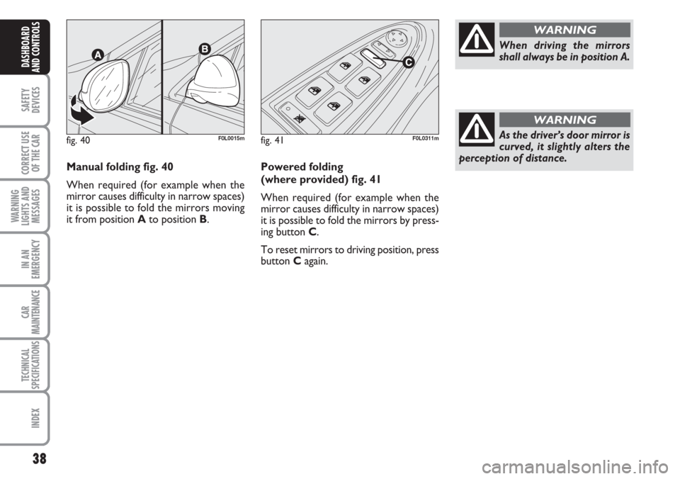
Manual folding fig. 40
When required (for example when the
mirror causes difficulty in narrow spaces)
it is possible to fold the mirrors moving
it from position Ato position B.
fig. 40F0L0015mfig. 41F0L0311m
Powered folding
(where provided) fig. 41
When required (for example when the
mirror causes difficulty in narrow spaces)
it is possible to fold the mirrors by press-
ing button C.
To reset mirrors to driving position, press
button Cagain.
When driving the mirrors
shall always be in position A.
WARNING
As the driver’s door mirror is
curved, it slightly alters the
perception of distance.
WARNING
Page 56 of 240
56
SAFETY
DEVICES
CORRECT USE
OF THE CAR
WARNING
LIGHTS AND
MESSAGES
IN AN
EMERGENCY
CAR
MAINTENANCE
TECHNICAL
SPECIFICATIONS
INDEX
DASHBOARD
AND CONTROLS
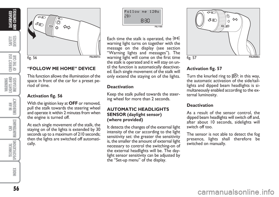
“FOLLOW ME HOME” DEVICE
This function allows the illumination of the
space in front of the car for a preset pe-
riod of time.
Activation fig. 56
With the ignition key at OFFor removed,
pull the stalk towards the steering wheel
and operate it within 2 minutes from when
the engine is turned off.
At each single movement of the stalk, the
staying on of the lights is extended by 30
seconds up to a maximum of 210 seconds;
then the lights are switched off automati-
cally. Each time the stalk is operated, the 3
warning light turns on together with the
message on the display (see section
“Warning lights and messages”). The
warning light will come on the first time
the stalk is operated and it will stay on un-
til the function is automatically deactivat-
ed. Each single movement of the stalk will
only extend the staying on of the lights.
Deactivation
Keep the stalk pulled towards the steer-
ing wheel for more than 2 seconds.
AUTOMATIC HEADLIGHTS
SENSOR (daylight sensor)
(where provided)
It detects the changes of the external light
intensity of the car according to the light
sensitivity set: the greater the sensitivity
is, the smaller the amount of external light
necessary to control the switching-on of
the external headlights will be. The day-
light sensor sensitivity can be adjusted by
the “Set-up menu” of the display.
fig. 56F0L0027m
F0L1150i
Activation fig. 57
Turn the knurled ring to
2A:in this way,
the automatic activation of the side/tail-
lights and dipped beam headlights is si-
multaneously enabled according to the ex-
ternal luminosity.
Deactivation
As a result of the sensor control, the
dipped beam headlights will switch off and,
after about 10 seconds, sidelights will
switch off too.
The sensor is not able to detect the fog
presence, lights shall therefore be
switched on manually.
fig. 57F0L0028m
Page 60 of 240
60
SAFETY
DEVICES
CORRECT USE
OF THE CAR
WARNING
LIGHTS AND
MESSAGES
IN AN
EMERGENCY
CAR
MAINTENANCE
TECHNICAL
SPECIFICATIONS
INDEX
DASHBOARD
AND CONTROLS
CRUISE CONTROL
(where provided)
It is a device able to support the driver,
with electronic control, which allows dri-
ving at speed over 30 km/h on long and
straight dry roads (e.g.: motorways), at a
desired speed, without pressing the ac-
celerator pedal. Therefore it is not sug-
gested to use this device on extra-urban
roads with traffic. Do not use it in town.
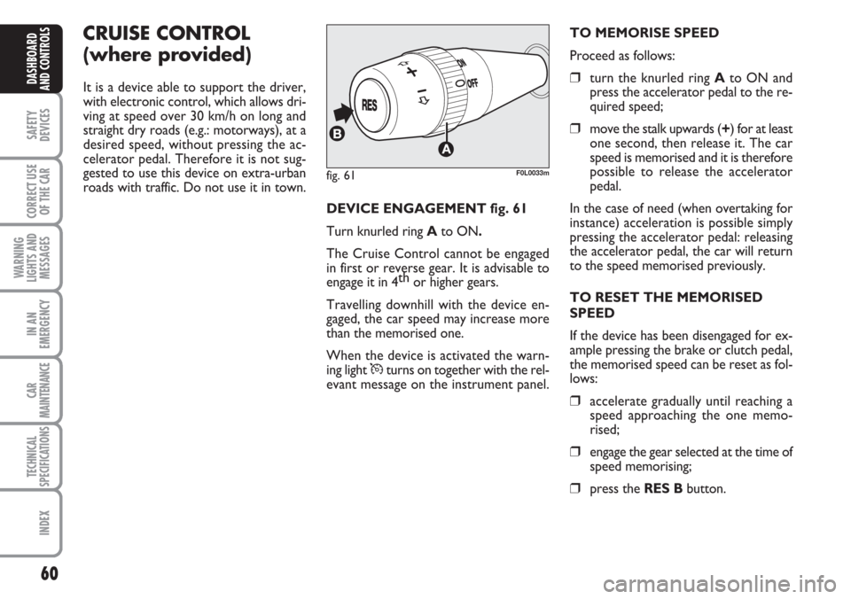
DEVICE ENGAGEMENT fig. 61
Turn knurled ring Ato ON.
The Cruise Control cannot be engaged
in first or reverse gear. It is advisable to
engage it in 4th
or higher gears.
Travelling downhill with the device en-
gaged, the car speed may increase more
than the memorised one.
When the device is activated the warn-
ing light
Üturns on together with the rel-
evant message on the instrument panel.TO MEMORISE SPEED
Proceed as follows:
❒turn the knurled ring Ato ON and
press the accelerator pedal to the re-
quired speed;
❒move the stalk upwards (+) for at least
one second, then release it. The car
speed is memorised and it is therefore
possible to release the accelerator
pedal.
In the case of need (when overtaking for
instance) acceleration is possible simply
pressing the accelerator pedal: releasing
the accelerator pedal, the car will return
to the speed memorised previously.
TO RESET THE MEMORISED
SPEED
If the device has been disengaged for ex-
ample pressing the brake or clutch pedal,
the memorised speed can be reset as fol-
lows:
❒accelerate gradually until reaching a
speed approaching the one memo-
rised;
❒engage the gear selected at the time of
speed memorising;
❒press the RES Bbutton.
fig. 61F0L0033m
Page 61 of 240
61
SAFETY
DEVICES
CORRECT USE
OF THE CAR
WARNING
LIGHTS AND
MESSAGES
IN AN
EMERGENCY
CAR
MAINTENANCE
TECHNICAL
SPECIFICATIONS
INDEX
DASHBOARD
AND CONTROLS
TO INCREASE THE MEMORISED
SPEED
The speed memorised can be increased in
two ways:
❒pressing the accelerator and then
memorising the new speed reached;
or
❒moving the stalk upwards (+).
Each operation of the stalk will corre-
spond to a slight increase in speed (about
1 km/h), while keeping the stalk upwards
will correspond to a continuous speed in-
crease.
TO REDUCE MEMORISED
SPEED
The speed memorised can be increased in
two ways:
❒disengaging the device and then mem-
orising the new speed;
or
❒moving the stalk downwards (–) until
reaching the new speed which will be
memorised automatically.
Each operation of the stalk will corre-
spond to a slight reduction in speed (about
1 km/h), while keeping the stalk down-
wards will correspond to a continuous
speed reduction.DEVICE DISENGAGEMENT
The device can be disengaged in the fol-
lowing ways:
❒turning the knurled ring Ato OFF;
❒turning the engine off;
❒pressing the brake pedal or engaging
the hand brake;
❒pressing the clutch pedal;
❒shifting gear with automatic transmis-
sion in sequential mode;
❒with car speed below the preset lim-
it;
❒pressing the accelerator pedal; in this
case the system is not really disen-
gaged but the request for acceleration
takes priority over the system. The
cruise control is however active and it
will not be necessary to press button
RES to resume previous conditions
after ending acceleration.The device is automatically deactivated in
one of the following cases:
❒ABS or ESP system cut-in;
❒system failure.
When travelling with the de-
vice on, never set the
gearshift lever to neutral.
WARNING
In the event of device mal-
function or failure, turn the
knurled ring A to OFF and contact a
Fiat Dealership after checking the
protection fuse integrity.
WARNING
Page 64 of 240
64
SAFETY
DEVICES
CORRECT USE
OF THE CAR
WARNING
LIGHTS AND
MESSAGES
IN AN
EMERGENCY
CAR
MAINTENANCE
TECHNICAL
SPECIFICATIONS
INDEX
DASHBOARD
AND CONTROLS
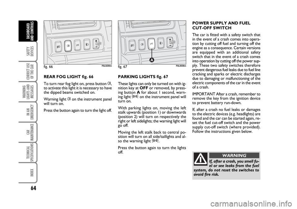
REAR FOG LIGHT fig. 66
To turn rear fog light on, press button 4,
to activate this light it is necessary to have
the dipped beams switched on.
Warning light 4on the instrument panel
will turn on.
Press the button again to turn the light off.PARKING LIGHTS fig. 67
These lights can only be turned on with ig-
nition key at OFFor removed, by press-
ing button Afor about 1 second, warn-
ing light 3on the instrument panel will
turn on.
With parking lights on, moving the left
stalk upwards (position 1) or downwards
(position 2) will turn on respectively the
right or left sidelights; the warning light will
go off.
Moving the left stalk back to central po-
sition will turn on all side/taillights and al-
so the warning light 3.
Press the button again to turn the lights
off. POWER SUPPLY AND FUEL
CUT-OFF SWITCH
The car is fitted with a safety switch that
in the event of a crash comes into opera-
tion by cutting off fuel and turning off the
engine as a consequence. Certain versions
are equipped with an additional safety
switch that in the event of a crash comes
into operation by cutting off the power sup-
ply. These two safety switches therefore
prevent dangerous fuel leaks due to fuel line
cracking and sparks or electric discharges
due to damaging or malfunctioning of the
electric components of the car in the event
of a crash.
IMPORTANT After a crash, remember to
remove the key from the ignition device
to prevent battery run-down.
If, after a crash no fuel leaks or damages
to the electric devices (e.g. headlights) are
found and the car can be started again, re-
set the fuel cut-off switch and the power
supply cut-off switch (where provided).
Follow the instructions given below.
fig. 66F0L0230mfig. 67F0L0036m
If, after a crash, you smell fu-
el or see leaks from the fuel
system, do not reset the switches to
avoid fire risk.
WARNING
062-098 Croma TRW GB 20-11-2006 15:01 Pagina 64