window FIAT CROMA 2006 2.G Owners Manual
[x] Cancel search | Manufacturer: FIAT, Model Year: 2006, Model line: CROMA, Model: FIAT CROMA 2006 2.GPages: 240, PDF Size: 7.41 MB
Page 4 of 240
4
SAFETY
DEVICES
CORRECT USE
OF THE CAR
WARNING
LIGHTS AND
MESSAGES
IN AN
EMERGENCY
CAR
MAINTENANCE
TECHNICAL
SPECIFICATIONS
INDEX
DASHBOARD
AND CONTROLSDASHBOARD ........................................................................ 5
INSTRUMENT PANEL ......................................................... 6
SYMBOLS ................................................................................. 7
THE FIAT CODE SYSTEM ................................................... 7
THE KEYS ................................................................................ 8
ALARM ..................................................................................... 12
IGNITION SWITCH.............................................................. 17
INSTRUMENTS ....................................................................... 18
SEATS ........................................................................................ 31
HEAD RESTRAINTS .............................................................. 34
STEERING WHEEL ............................................................... 35
REARVIEW MIRRORS ........................................................... 36
HEATING/CLIMATE
CONTROL SYSTEM ............................................................. 39
MANUAL CLIMATE CONTROL SYSTEM .................... 41
AUTOMATIC CLIMATE CONTROL SYSTEM ............ 44
EXTERNAL LIGHTS .............................................................. 54
WINDOW WASHING......................................................... 57
CRUISE CONTROL ............................................................. 60
CEILING LIGHTS .................................................................. 62
CONTROLS ........................................................................... 63
INTERIOR FITTINGS ............................................................ 66SUNROOF................................................................................ 70
DOORS .................................................................................... 73
POWER WINDOWS ........................................................... 74
BOOT ........................................................................................ 76
BONNET .................................................................................. 82
HEADLIGHTS .......................................................................... 85
ABS SYSTEM ........................................................................... 86
ESP SYSTEM ............................................................................ 88
ASR SYSTEM ........................................................................... 89
EOBD SYSTEM ....................................................................... 90
T.P.M.S. SYSTEM .................................................................... 91
SOUND SYSTEM .................................................................... 92
ACCESSORIES PURCHASED BY THE OWNER .......... 93
PARKING SENSORS ............................................................ 94
AT THE FILLING STATION .............................................. 95
PROTECTING THE ENVIRONMENT ............................ 97
DIESEL PARTICULATE FILTER (DPF) ............................. 98
D D
A A
S S
H H
B B
O O
A A
R R
D D
A A
N N
D D
C C
O O
N N
T T
R R
O O
L L
S S
001-030 Croma TRW GB 20-11-2006 14:58 Pagina 4
Page 5 of 240
DASHBOARD
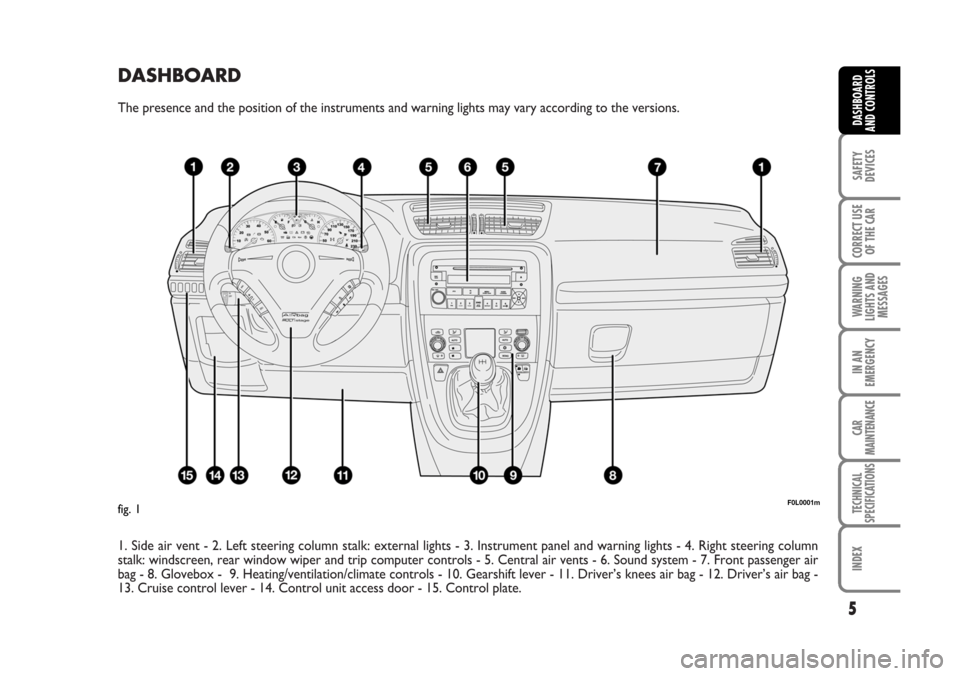
The presence and the position of the instruments and warning lights may vary according to the versions.
1. Side air vent - 2. Left steering column stalk: external lights - 3. Instrument panel and warning lights - 4. Right steering column
stalk: windscreen, rear window wiper and trip computer controls - 5. Central air vents - 6. Sound system - 7. Front passenger air
bag - 8. Glovebox - 9. Heating/ventilation/climate controls - 10. Gearshift lever - 11. Driver’s knees air bag - 12. Driver’s air bag -
13. Cruise control lever - 14. Control unit access door - 15. Control plate.
5
SAFETY
DEVICES
CORRECT USE
OF THE CAR
WARNING
LIGHTS AND
MESSAGES
IN AN
EMERGENCY
CAR
MAINTENANCE
TECHNICAL
SPECIFICATIONS
INDEX
DASHBOARD
AND CONTROLS
F0L0001mfig. 1
001-030 Croma TRW GB 20-11-2006 14:58 Pagina 5
Page 9 of 240
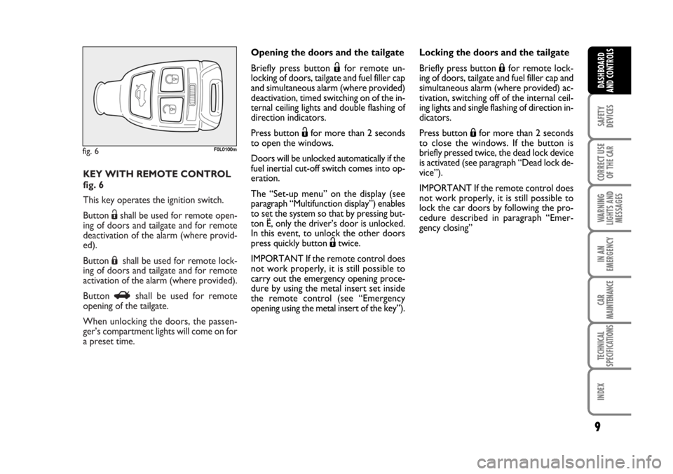
KEY WITH REMOTE CONTROL
fig. 6
This key operates the ignition switch.
Button Ëshall be used for remote open-
ing of doors and tailgate and for remote
deactivation of the alarm (where provid-
ed).
Button Áshall be used for remote lock-
ing of doors and tailgate and for remote
activation of the alarm (where provided).
Button Rshall be used for remote
opening of the tailgate.
When unlocking the doors, the passen-
ger’s compartment lights will come on for
a preset time.
fig. 6F0L0100m
9
SAFETY
DEVICES
CORRECT USE
OF THE CAR
WARNING
LIGHTS AND
MESSAGES
IN AN
EMERGENCY
CAR
MAINTENANCE
TECHNICAL
SPECIFICATIONS
INDEX
DASHBOARD
AND CONTROLS
Opening the doors and the tailgate
Briefly press button Ëfor remote un-
locking of doors, tailgate and fuel filler cap
and simultaneous alarm (where provided)
deactivation, timed switching on of the in-
ternal ceiling lights and double flashing of
direction indicators.
Press button Ëfor more than 2 seconds
to open the windows.
Doors will be unlocked automatically if the
fuel inertial cut-off switch comes into op-
eration.
The “Set-up menu” on the display (see
paragraph “Multifunction display”) enables
to set the system so that by pressing but-
ton Ë, only the driver’s door is unlocked.
In this event, to unlock the other doors
press quickly button Ëtwice.
IMPORTANT If the remote control does
not work properly, it is still possible to
carry out the emergency opening proce-
dure by using the metal insert set inside
the remote control (see “Emergency
opening using the metal insert of the key”).Locking the doors and the tailgate
Briefly press button Áfor remote lock-
ing of doors, tailgate and fuel filler cap and
simultaneous alarm (where provided) ac-
tivation, switching off of the internal ceil-
ing lights and single flashing of direction in-
dicators.
Press button Áfor more than 2 seconds
to close the windows. If the button is
briefly pressed twice, the dead lock device
is activated (see paragraph “Dead lock de-
vice”).
IMPORTANT If the remote control does
not work properly, it is still possible to
lock the car doors by following the pro-
cedure described in paragraph “Emer-
gency closing”
001-030 Croma TRW GB 20-11-2006 14:58 Pagina 9
Page 13 of 240
13
SAFETY
DEVICES
CORRECT USE
OF THE CAR
WARNING
LIGHTS AND
MESSAGES
IN AN
EMERGENCY
CAR
MAINTENANCE
TECHNICAL
SPECIFICATIONS
INDEX
DASHBOARD
AND CONTROLS
HOW TO DEACTIVATE
THE ALARM fig. 12
Press button
Ëof the key with remote
control.
The system will react as follows (with the
exception of certain markets):
❒two brief flashes of the direction in-
dicators;
❒two brief “beeps”;
❒door unlocking.
IMPORTANT Operating a door with the
metal insert of the key will not activate the
alarm.
To deactivate the alarm, turn the ignition
key to ON.
fig. 13F0L0171m
VOLUMETRIC PROTECTION
SENSORS
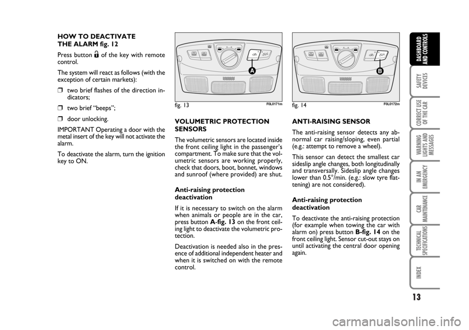
The volumetric sensors are located inside
the front ceiling light in the passenger’s
compartment. To make sure that the vol-
umetric sensors are working properly,
check that doors, boot, bonnet, windows
and sunroof (where provided) are shut.
Anti-raising protection
deactivation
If it is necessary to switch on the alarm
when animals or people are in the car,
press button A-fig. 13 on the front ceil-
ing light to deactivate the volumetric pro-
tection.
Deactivation is needed also in the pres-
ence of additional independent heater and
when it is switched on with the remote
control.
fig. 14F0L0172m
ANTI-RAISING SENSOR
The anti-raising sensor detects any ab-
normal car raising/sloping, even partial
(e.g.: attempt to remove a wheel).
This sensor can detect the smallest car
sideslip angle changes, both longitudinally
and transversally. Sideslip angle changes
lower than 0.5°/min. (e.g.: slow tyre flat-
tening) are not considered).
Anti-raising protection
deactivation
To deactivate the anti-raising protection
(for example when towing the car with
alarm on) press button B-fig. 14on the
front ceiling light. Sensor cut-out stays on
until activating the central door opening
again.
001-030 Croma TRW GB 20-11-2006 14:58 Pagina 13
Page 14 of 240
Once the dead lock device
has been actuated, doors
cannot be opened from inside the car
in any way whatsoever. For this rea-
son, make sure there are no persons
left inside the car.
14
SAFETY
DEVICES
CORRECT USE
OF THE CAR
WARNING
LIGHTS AND
MESSAGES
IN AN
EMERGENCY
CAR
MAINTENANCE
TECHNICAL
SPECIFICATIONS
INDEX
DASHBOARD
AND CONTROLS
INDICATIONS OF ATTEMPTS
TO BREAK IN
Any attempt to break in is indicated by
turning on of warning light
Y(if pro-
vided) on the instrument panel with the
relevant message on the display (see sec-
tion “Warning lights and messages”).
HOW TO CUT OFF THE ALARM
SYSTEM
To deactivate the alarm system com-
pletely (for instance during prolonged in-
activity of the car) simply lock the car us-
ing the emergency locking.
IMPORTANT To cut-out the alarm if re-
mote control batteries are down or the
system is failing, fit the key into the igni-
tion switch and turn it to ON.
DEAD LOCK DEVICE
(where provided)
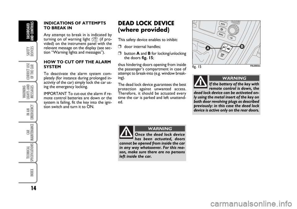
This safety device enables to inhibit:
❒door internal handles;
❒button Aand Bfor locking/unlocking
the doors fig. 15;
thus hindering doors opening from inside
the passenger’s compartment in case of
attempt to break-into (e.g. window break-
ing).
The dead lock device guarantees the best
protection against unwanted access.
Therefore, it should be actuated every
time the car is parked and left unattend-
ed.
fig. 15F0L0003m
WARNING
If the battery of the key with
remote control is down, the
dead lock device can be activated on-
ly using the metal insert of the key on
both door revolving plugs as described
previously: in this case the dead lock
device is active only on the rear doors.
WARNING
001-030 Croma TRW GB 20-11-2006 14:58 Pagina 14
Page 16 of 240
16
SAFETY
DEVICES
CORRECT USE
OF THE CAR
WARNING
LIGHTS AND
MESSAGES
IN AN
EMERGENCY
CAR
MAINTENANCE
TECHNICAL
SPECIFICATIONS
INDEX
DASHBOARD
AND CONTROLS
Key with
remote control
Emergency
metal
insert
Direction
indicators
flashing (only
with key with
remote control)
Led on
driver’s door
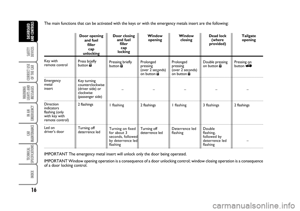
IMPORTANT The emergency metal insert will unlock only the door being operated.
IMPORTANT Window opening operation is a consequence of a door unlocking control; window closing operation is a consequence
of a door locking control.
Door opening
and fuel
filler
cap
unlocking
Press briefly
button
Ë
Key turning
counterclockwise
(driver side) or
clockwise
(passenger side)
2 flashings
Turning off
deterrence ledDoor closing
and fuel
filler
cap
locking
Pressing briefly
button Á
–
1 flashing
Turning on fixed
for about 3
seconds, followed
by deterrence led
flashingWindow
opening
Prolonged
pressing
(over 2 seconds)
on button Ë
–
2 flashings
Turning off
deterrence ledWindow
closing
Prolonged
pressing
(over 2 seconds)
on button Á
–
1 flashing
Deterrence led
flashingDead lock
(where
provided)
Double pressing
on button Á
–
3 flashings
Double
flashing,
followed by
deterrence led
flashingTailgate
opening
Pressing on
button R
–
2 flashings
–
The main functions that can be activated with the keys or with the emergency metals insert are the following:
001-030 Croma TRW GB 20-11-2006 14:58 Pagina 16
Page 17 of 240
17
SAFETY
DEVICES
CORRECT USE
OF THE CAR
WARNING
LIGHTS AND
MESSAGES
IN AN
EMERGENCY
CAR
MAINTENANCE
TECHNICAL
SPECIFICATIONS
INDEX
DASHBOARD
AND CONTROLS
IGNITION SWITCH
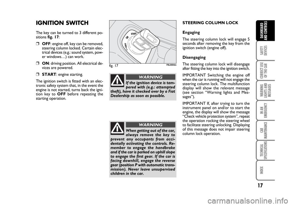
The key can be turned to 3 different po-
sitions fig. 17:
❒OFF: engine off, key can be removed,
steering column locked. Certain elec-
trical devices (e.g.: sound system, pow-
er windows…) can work.
❒ON: driving position. All electrical de-
vices are powered.
❒START: engine starting.
The ignition switch is fitted with an elec-
tronic safety system that, in the event the
engine is not started, turns back the igni-
tion key to OFFbefore repeating the
starting operation.
fig. 17F0L0004m
If the ignition device is tam-
pered with (e.g.: attempted
theft), have it checked over by a Fiat
Dealership as soon as possible.
WARNING
When getting out of the car,
always remove the key to
prevent any occupants from acci-
dentally activating the controls. Re-
member to engage the handbrake
and if the car is parked on uphill slope
to engage the first gear. If the car is
facing downhill, engage the reverse
gear (position P with automatic trans-
mission). Never leave unsupervised
children in the car.
WARNING
STEERING COLUMN LOCK
Engaging
The steering column lock will engage 5
seconds after removing the key from the
ignition switch (engine off).
Disengaging
The steering column lock will disengage
after fitting the key into the ignition switch.
IMPORTANT Switching the engine off
when the car is running will not engage the
steering column lock. The multifunction
display will show the relevant message
(see section “Warning lights and Mes-
sages”).
IMPORTANT If, after trying to turn the
instrument panel on and/or to start the
engine, the display will show the message
“Check vehicle protection system”, repeat
the operation rocking the steering wheel
to facilitate steering unlocking. Displaying
of this message does not impair steering
column lock operation.
001-030 Croma TRW GB 20-11-2006 14:58 Pagina 17
Page 36 of 240
36
SAFETY
DEVICES
CORRECT USE
OF THE CAR
WARNING
LIGHTS AND
MESSAGES
IN AN
EMERGENCY
CAR
MAINTENANCE
TECHNICAL
SPECIFICATIONS
INDEX
DASHBOARD
AND CONTROLS
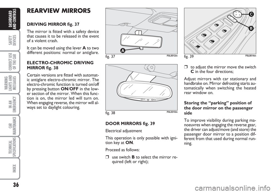
fig. 37F0L0012m
REARVIEW MIRRORS
DRIVING MIRROR fig. 37
The mirror is fitted with a safety device
that causes it to be released in the event
of a violent crash.
It can be moved using the lever Ato two
different positions: normal or antiglare.
ELECTRO-CHROMIC DRIVING
MIRROR fig. 38
Certain versions are fitted with automat-
ic antiglare electro-chromic mirror. The
electro-chromic function is turned on/off
by pressing button ON/OFFin the low-
er section of the mirror. When this func-
tion is on, the mirror led will turn on.
When engaging reverse, the mirror will al-
ways set to daylight colouring.
DOOR MIRRORS fig. 39
Electrical adjustment
This operation is only possible with igni-
tion key at ON.
Proceed as follows:
❒use switch Bto select the mirror re-
quired (left or right);
❒to adjust the mirror move the switch
Cin the four directions;
Adjust mirrors with car stationary and
handbrake on. Mirror defrosting starts au-
tomatically when switching the heated
rear window on.
Storing the “parking” position of
the door mirror on the passenger
side
To improve visibility during parking ma-
noeuvres when engaging the reverse gear,
the driver can adjust/move (and store) the
passenger door mirror to a position dif-
ferent from that used during normal run-
ning.
fig. 38F0L0310m
fig. 39F0L0014m
Page 41 of 240
41
SAFETY
DEVICES
CORRECT USE
OF THE CAR
WARNING
LIGHTS AND
MESSAGES
IN AN
EMERGENCY
CAR
MAINTENANCE
TECHNICAL
SPECIFICATIONS
INDEX
DASHBOARD
AND CONTROLS
MANUAL CLIMATE
CONTROL SYSTEM
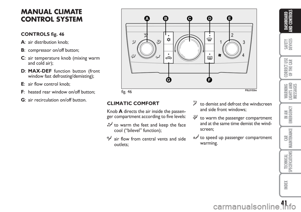
CONTROLS fig. 46
A: air distribution knob;
B: compressor on/off button;
C: air temperature knob (mixing warm
and cold air);
D:MAX-DEFfunction button (front
window fast defrosting/demisting);
E: air flow control knob;
F: heated rear window on/off button;
G: air recirculation on/off button.
F0L0153m
CLIMATIC COMFORT
Knob Adirects the air inside the passen-
ger compartment according to five levels:
Mto warm the feet and keep the face
cool (“bilevel” function);
Oair flow from central vents and side
outlets;
yto demist and defrost the windscreen
and side front windows;
™to warm the passenger compartment
and at the same time demist the wind-
screen;
Nto speed up passenger compartment
warming.
fig. 46
Page 42 of 240
42
SAFETY
DEVICES
CORRECT USE
OF THE CAR
WARNING
LIGHTS AND
MESSAGES
IN AN
EMERGENCY
CAR
MAINTENANCE
TECHNICAL
SPECIFICATIONS
INDEX
DASHBOARD
AND CONTROLS
WARMING THE PASSENGER
COMPARTMENT
Proceed as follows:
❒turn knob C(pointer on red sector)
completely to the right;
❒turn knob Eto the required speed;
❒move knob Ato:
™to warm the feet and at the same
time demist the windscreen;
Mto warm the feet and convey cooler
air from central vents and dashboard
outlets;
Nfor quick warming.QUICK WARMING
Proceed as follows:
❒close all dashboard vents;
❒turn knob Cto red sector;
❒press button G;
❒turn knob Eto the required fan speed;
❒turn knob Ato N.WINDSCREEN AND FRONT
SIDE WINDOW FAST
DEMISTING/DEFROSTING
(MAX-DEF function)
Proceed as follows:
❒turn knob C(pointer on red sector)
completely to the right;
❒turn the MAX-DEFfunction on by
pressing button D(button led on);
Pressing this button will automatically acti-
vate the following functions:
❒air distribution to windscreen and side
vents;
❒fan activation at max. speed;
❒compressor activation (button led on);
❒automatic air recirculation (button led
off if previously on);
After demisting/defrosting, press button
Dto turn the MAX-DEFfunction off.
Use common control buttons to restore
the required comfort.