technical data FIAT DOBLO 2009 2.G Owners Manual
[x] Cancel search | Manufacturer: FIAT, Model Year: 2009, Model line: DOBLO, Model: FIAT DOBLO 2009 2.GPages: 274, PDF Size: 6.6 MB
Page 21 of 274
20
KNOW
YOUR
VEHICLE
SAFETY
STARTING
AND
DRIVING
WARNING
LIGHTS AND
MESSAGES
IN AN
EMERGENCY
SERVICING
AND
MAINTENANCE
TECHNICAL
SPECIFICATIONS
INDEXSETUP MENU
The menu comprises a series of functions arranged in a cir-
cle which can be selected through buttons ▲and ▼to
access the settings described below. A submenu is pro-
vided for some items (Clock and Unit of measurement).
The setup menu can be activated by pressing SET ESC.
Pressing buttons ▲or ▼scrolls through the setup menu
options. Management modes differ from each other ac-
cording to the option selected. The menu comprises the
following functions:
– LIGHTING
– SPEED BEEP
– TRIP B DATA
– SET TIME
– SET DATE
– RADIO INFO (if present)
– AUTOCLOSE
– UNIT OF MEASUREMENT
– LANGUAGE
– WARNING VOLUME
– BUTTON VOLUME
– SEAT BELT BUZZER
(only if previously disabled)
– SERVICE N.B. Buttons ▲and ▼activate different functions in the
following situations:
Adjusting the vehicle’s interior lighting
– on the standard screen, they adjust the brightness of
the instrument panel and the radio.
Setup menu
– within the menu, they scroll up and down;
– during setting operations they increase or decrease the
value.
Page 23 of 274
22
KNOW
YOUR
VEHICLE
SAFETY
STARTING
AND
DRIVING
WARNING
LIGHTS AND
MESSAGES
IN AN
EMERGENCY
SERVICING
AND
MAINTENANCE
TECHNICAL
SPECIFICATIONS
INDEX– press ▲or ▼to select;
– press the SET ESC button to go back to the menu screen
or hold the button down to go back to the standard screen
without saving.
Setting the time (Clock)
This function allows you to set the clock through two sub-
menus: “Time” and “Mode”.
To carry out the adjustment, proceed as follows:
– press SET ESC: the display shows the two submenus
“Time” and “Mode”;
– press ▲or ▼to move between the two submenus;
– once you have selected a submenu, press SET ESC; – if the function is on, press ▲or ▼to select the re-
quired speed limit and then press SET ESC to confirm;
N.B. The speed may be set anywhere between 30 and
200 km/h or 20 and 125 mph, depending on the previ-
ously chosen unit (see “Setting the unit of measurement
(Unit)”). The setting will increase/decrease by five units
each time button ▲/▼is pressed. Hold down button ▲/▼
to increase/decrease the setting rapidly. Complete the
setting with single presses of the button when you ap-
proach the required setting.
– press the SET ESC button to go back to the menu screen
or hold the button down to go back to the standard screen
without saving.
To cancel the setting, proceed as follows:
– press the SET ESC button: ON flashes in the display;
– press button ▼: OFF flashes in the display;
– press the SET ESC button to go back to the menu screen
or hold the button down to go back to the standard screen
without saving.
Trip B data (Activating Trip B)
This function may be used to activate (On) or deactivate
(Off) the Trip B display (partial trip).
For more information see the „Trip computer” section.
For activation/deactivation, proceed as follows:
– press the SET ESC button again: the display flashes On
or Off depending on what was previously set;
Page 115 of 274
114
KNOW
YOUR
VEHICLE
SAFETY
STARTING
AND
DRIVING
WARNING
LIGHTS AND
MESSAGES
IN AN
EMERGENCY
SERVICING
AND
MAINTENANCE
TECHNICAL
SPECIFICATIONS
INDEX
DIESEL PARTICULATE FILTER (DPF)
(for versions/markets where provided)
The Diesel Particulate Filter is a mechanical filter, inte-
gral with the exhaust system, that physically traps carbon
particles present in the exhaust gases of Diesel engines.
It is needed to eliminate almost all carbon particles in com-
pliance with current/future legislation. During normal use
of the vehicle, the engine management control unit records
a set of data (e.g. journey time, type of route, tempera-
tures, etc.) and it will then calculate how much particu-
late has been trapped by the filter.Since the filter is a collecting system, it should be regular-
ly regenerated (cleaned) by burning the carbon particles.
The regeneration procedure is controlled automatically by
the engine management control unit according to the fil-
ter conditions and vehicle use conditions.
During regeneration, the following may occur: a limited in-
crease in the engine speed, activation of the fan, a limited
increase in fumes and high temperatures at the exhaust.
These are not faults; they do not impair vehicle perfor-
mance or damage the environment. If the dedicated mes-
sage is displayed, refer to the “Warning lights and mes-
sages” section.
Page 121 of 274
120
KNOW
YOUR
VEHICLE
SAFETY
STARTING
AND
DRIVING
WARNING
LIGHTS AND
MESSAGES
IN AN
EMERGENCY
SERVICING
AND
MAINTENANCE
TECHNICAL
SPECIFICATIONS
INDEX
SEAT BELT MAINTENANCE
Observe the following precautions for correct seat belt
maintenance:
❒always make sure the belt is well stretched and never
twisted; make sure that it is free to run without ob-
structions;
❒replace the belt after a serious accident, even if it does
not appear damaged. Always replace the seat belt if the
pretensioners were deployed;
❒To clean the belt, wash by hand with water and mild
soap, rinse and leave to dry in the shade. Do not use
strong detergents, bleach, paints or any other chemi-
cals which could damage the belt fibres;
❒prevent the reels from getting wet: their correct op-
eration is guaranteed only if water does not get inside;
❒replace the seat belt if it shows significant signs of wear
and tear.
If the belt has been subjected to heavy
stress, for example after an accident, it
should be changed completely together with the
anchors, anchor fastening screws and the preten-
sioner. In fact, even if the belt has no visible de-
fects, it could have lost its resilience.
WARNINGCARRYING CHILDREN SAFELY
For optimum protection in the event of a crash, all pas-
sengers must be seated and wearing adequate restraint
systems.
This is even more important for children.
This prescription is compulsory in all EU countries ac-
cording to EC Directive 2003/20/EC.
Compared with an adult, a child’s head is larger and heav-
ier in proportion to his/her body and the child’s muscu-
lar and bone structures are not fully developed. For this
reason, they require restraint systems which are differ-
ent from those used by adults to protect them in the event
of an accident.
The result of research in relation to the best protection
for children is illustrated in European Regulation ECE-R44,
which divides the restraint systems into five groups in ad-
dition to making their use compulsory:
Group 0 up to 10 kg
Group 0+ up to 13 kg
Group 1 9-18 kg
Group 2 15-25 kg
Group 3 22-36 kg
As you can see, the groups overlap partly and, in fact, there
are devices on sale that cover more than one weight group.
All restraint devices must bear the type-approval data along
with the control mark on a label firmly secured to the
child seat which must never be removed.
Page 220 of 274
219
KNOW
YOUR
VEHICLE
SAFETY
STARTING
AND
DRIVING
WARNING
LIGHTS AND
MESSAGES
IN AN
EMERGENCY
SERVICING
AND
MAINTENANCE
TECHNICAL
SPECIFICATIONS
INDEX
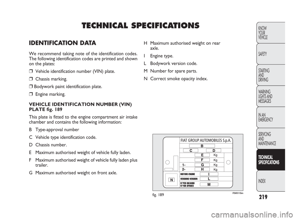
F0V0115mfig. 189
H Maximum authorised weight on rear
axle.
I Engine type.
L Bodywork version code.
M Number for spare parts.
N Correct smoke opacity index.
TECHNICAL SPECIFICATIONS
IDENTIFICATION DATA
We recommend taking note of the identification codes.
The following identification codes are printed and shown
on the plates:
❒Vehicle identification number (VIN) plate.
❒Chassis marking.
❒Bodywork paint identification plate.
❒Engine marking.
VEHICLE IDENTIFICATION NUMBER (VIN)
PLATE fig. 189
This plate is fitted to the engine compartment air intake
chamber and contains the following information:
B Type-approval number
C Vehicle type identification code.
D Chassis number.
E Maximum authorised weight of vehicle fully laden.
F Maximum authorised weight of vehicle fully laden plus
trailer.
G Maximum authorised weight on front axle.
Page 266 of 274
265
KNOW
YOUR
VEHICLE
SAFETY
STARTING
AND
DRIVING
WARNING
LIGHTS AND
MESSAGES
IN AN
EMERGENCY
SERVICING
AND
MAINTENANCE
TECHNICAL
SPECIFICATIONS
INDEX
Front airbags ......................... 128
– deactivation...................... 130
– driver’s side..................... 129
– passenger’s side.............. 129
Front armrest ......................... 71
Front ceiling light ................... 65
– bulb replacement ........... 178
Front fog lights
– bulb replacement ............ 174
– switching on....................... 70
Front light clusters
– bulb arrangement ........... 172
Front seats............................... 31
– adjusting .......................30-31
– armrest .............................. 71
– cleaning ............................ 216
– headrests ........................... 37
– heating ..........................30-32
Fuel consumption .................249
Fuel cut-off system ................70Fuel economy....................... 137
Fuel flap ................................ 112
Fuel gauge ............................... 13
– type of fuel ............. 111-112
Fuel reserve warning
light ...................................... 150
Fuel reserve ......................... 246
Fuel supply
(technical data) .................. 224
Fuel tank (capacity) ............. 246
Fuel tank cap ....................... 112
Fuel
– at the pump ............ 111-112
– consumption ................... 249
– fuel cut-off system ........... 70
– gauge and reserve
warning light ..................... 13
– opening the flap ............. 112
– refuelling .................111-112
– specifications ..........111-112
– tank cap ........................... 112Fuse boxes
(location) ....................182-186
Fuse list
.......
182-183-184-185-186-187
Fuse replacement
– general information
and warnings.................... 181
– list
......
182-183-184-185-186-187
– location (fuse boxes)
.....................................182-186
Fuse summary table
.....182-183-184-185-186-187
Fuses
.....182-183-184-185-186-187
– general information
and warnings.................... 181
– location (fuse boxes)
...................................182-186
Gear stick.............................. 136
Gearbox................................ 136
Page 267 of 274
266
KNOW
YOUR
VEHICLE
SAFETY
STARTING
AND
DRIVING
WARNING
LIGHTS AND
MESSAGES
IN AN
EMERGENCY
SERVICING
AND
MAINTENANCE
TECHNICAL
SPECIFICATIONS
INDEX
– technical
specifications................... 224
Glove compartment ............. 71
Handbrake lever.................. 135
Handbrake ........................... 135
Hazard warning lights
– switching on ...................... 70
Headlamp alignment
corrector............................... 95
Headlamp washers................ 62
– checking levels
and topping up................ 203
– headlamp washer fluid
specifications................... 248
Headlight alignment
corrector .............................. 95
Headlights ............................... 95
– adjusting headlights
abroad ..................................96
– alignment corrector ......... 95– bulb replacement ........... 169
– bulbs (type) ............ 170-171
– light beam direction ......... 95
Headrests
– front ................................... 38
– rear ...................................... 38
Heated rear
window......................46-49-58
Heating and ventilation
system; .................................. 42
Heating and ventilation ......... 44
Heavy use of the vehicle .... 198
Hill Holder system................. 99
Identification data........ 219-220
Ignition keyhole ....................... 9
Ignition lock .............................. 9
Ignition ...................................... 9
In an emergency ................. 155Installing electrical/
electronic devices ............. 110
– radio transmitters
and mobile phones ........ 110
Installing the tow hook ..... 139
Instrument panel ................... 11
Interior fittings ...................... 71
Interior lighting
– front .......................65-66-69
– rear ...................66-67-68-69
Interiors (cleaning) ............. 216
Internal equipment ............... 71
Isofix child seat
– suitability for using
child seats ....................... 124
– capability for Isofix
child seat.......................... 125
Jack
– precautions...................... 158
– usage ................................. 159