tow FIAT DOBLO COMBI 2010 Owner handbook (in English)
[x] Cancel search | Manufacturer: FIAT, Model Year: 2010, Model line: DOBLO COMBI, Model: FIAT DOBLO COMBI 2010Pages: 274, PDF Size: 6.16 MB
Page 11 of 274
10
KNOW
YOUR
VEHICLE
SAFETY
STARTING
AND
DRIVING
WARNING
LIGHTS AND
MESSAGES
IN AN
EMERGENCY
SERVICING
AND
MAINTENANCE
TECHNICAL
SPECIFICATIONS
INDEX
Never extract the key while the vehicle is
moving. The steering wheel should lock au-
tomatically as soon as it is turned. This is always
the case, even when the vehicle is being towed.
WARNING
It is absolutely forbidden to carry out any
aftersales operation involving steering sys-
tem or steering column modifications (e.g. installing
an anti-theft device) that could badly affect per-
formance and safety, invalidate the warranty and
also result in the vehicle failing to comply with reg-
ulations.
WARNING
When getting out of the vehicle, always re-
move the key to prevent someone from
accidentally activating the controls. Remember to
engage the handbrake. Engage first gear if the ve-
hicle is parked uphill or reverse gear if the vehi-
cle is parked downhill. Never leave children un-
attended in the vehicle.
WARNING
001-034 DOBLO LUM EN 2e 7.0 21-05-2010 8:38 Pagina 10
Page 29 of 274
28
KNOW
YOUR
VEHICLE
SAFETY
STARTING
AND
DRIVING
WARNING
LIGHTS AND
MESSAGES
IN AN
EMERGENCY
SERVICING
AND
MAINTENANCE
TECHNICAL
SPECIFICATIONS
INDEX
Values displayed
Range
Shows the approximate distance the vehicle can travel with
the amount of fuel left in the tank. The display will show
the reading “----” when the following events take place:
– range is lower than 50 km (or 30 mi)
– vehicle is left parked with the engine running for a long
time.
WARNING The range can be affected by several factors:
driving style (see “Driving style” in the “Starting and dri-
ving” section), type of route (motorway, towns and cities,
mountain roads, etc.), conditions of use (load, tyre pres-
sures, etc.). Trip planning must therefore take the above
into account.
Distance travelled
Shows the distance covered since the start of the new jour-
ney.
Average consumption
Shows the approximate average fuel consumption since
the start of the new journey.
Current consumption
Shows the constantly updated fuel consumption. The read-
ing “----” appears on the display if the vehicle is parked with
the engine running.
Average speed
Shows the average speed of the vehicle by using the over-
all time elapsed since the start of a new journey.TRIP COMPUTER
General information
The Trip computer is used to display information on ve-
hicle operation when the ignition key is turned to MAR.
This function allows you to define two separate trips, called
“Trip A” and “Trip B”, for monitoring the vehicle’s „com-
plete mission” (journey) in a reciprocally independent man-
ner. Both functions can be reset (reset – start of a new
journey).
“Trip A” is used to display the figures relating to:
– Range
– Distance travelled
– Average consumption
– Instant consumption
– Average speed
– Travel time (driving time).
“Trip B”, available on multifunction display only, is used to
display the figures relating to:
– Distance travelled B
– Average consumption B
– Average speed B
– Travel time B (driving time).
N.B. “Trip B” may be disabled (see “Activating Trip B”).
“Range” and “Instant consumption” parameters cannot be
reset.
001-034 DOBLO LUM EN 2e 7.0 21-05-2010 8:38 Pagina 28
Page 40 of 274
39
KNOW
YOUR
VEHICLE
SAFETY
STARTING
AND
DRIVING
WARNING
LIGHTS AND
MESSAGES
IN AN
EMERGENCY
SERVICING
AND
MAINTENANCE
TECHNICAL
SPECIFICATIONS
INDEX
F0V0014mfig. 34
STEERING WHEEL
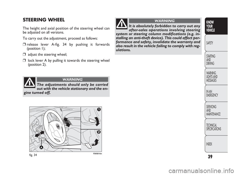
The height and axial position of the steering wheel can
be adjusted on all versions.
To carry out the adjustment, proceed as follows:
❒release lever A-fig. 34 by pushing it forwards
(position 1);
❒adjust the steering wheel;
❒lock lever A by pulling it towards the steering wheel
(position 2).
The adjustments should only be carried
out with the vehicle stationary and the en-
gine turned off.
WARNING
It is absolutely forbidden to carry out any
after-sales operations involving steering
system or steering column modifications (e.g. in-
stalling an anti-theft device). This could affect per-
formance and safety, invalidate the warranty and
also result in the vehicle failing to comply with reg-
ulations.
WARNING
035-114 DOBLO LUM EN 2e 7.0 21-05-2010 9:54 Pagina 39
Page 60 of 274
59
KNOW
YOUR
VEHICLE
SAFETY
STARTING
AND
DRIVING
WARNING
LIGHTS AND
MESSAGES
IN AN
EMERGENCY
SERVICING
AND
MAINTENANCE
TECHNICAL
SPECIFICATIONS
INDEX
F0V0052mfig. 45
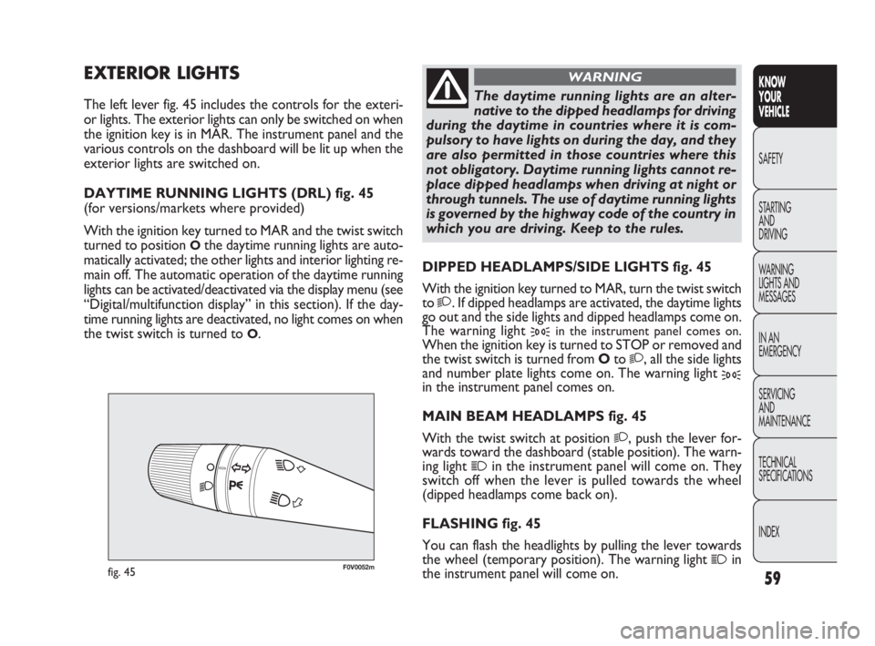
DIPPED HEADLAMPS/SIDE LIGHTS fig. 45
With the ignition key turned to MAR, turn the twist switch
to
2. If dipped headlamps are activated, the daytime lights
go out and the side lights and dipped headlamps come on.
The warning light
3in the instrument panel comes on.
When the ignition key is turned to STOP or removed and
the twist switch is turned from Oto
2, all the side lights
and number plate lights come on. The warning light
3in the instrument panel comes on.
MAIN BEAM HEADLAMPS fig. 45
With the twist switch at position
2, push the lever for-
wards toward the dashboard (stable position). The warn-
ing light
1in the instrument panel will come on. They
switch off when the lever is pulled towards the wheel
(dipped headlamps come back on).
FLASHING fig. 45
You can flash the headlights by pulling the lever towards
the wheel (temporary position). The warning light
1in
the instrument panel will come on.
EXTERIOR LIGHTS
The left lever fig. 45 includes the controls for the exteri-
or lights. The exterior lights can only be switched on when
the ignition key is in MAR. The instrument panel and the
various controls on the dashboard will be lit up when the
exterior lights are switched on.
DAYTIME RUNNING LIGHTS (DRL) fig. 45
(for versions/markets where provided)
With the ignition key turned to MAR and the twist switch
turned to position
Othe daytime running lights are auto-
matically activated; the other lights and interior lighting re-
main off. The automatic operation of the daytime running
lights can be activated/deactivated via the display menu (see
“Digital/multifunction display” in this section). If the day-
time running lights are deactivated, no light comes on when
the twist switch is turned to
O.
The daytime running lights are an alter-
native to the dipped headlamps for driving
during the daytime in countries where it is com-
pulsory to have lights on during the day, and they
are also permitted in those countries where this
not obligatory. Daytime running lights cannot re-
place dipped headlamps when driving at night or
through tunnels. The use of daytime running lights
is governed by the highway code of the country in
which you are driving. Keep to the rules.
WARNING
035-114 DOBLO LUM EN 2e 7.0 21-05-2010 9:54 Pagina 59
Page 61 of 274
60
KNOW
YOUR
VEHICLE
SAFETY
STARTING
AND
DRIVING
WARNING
LIGHTS AND
MESSAGES
IN AN
EMERGENCY
SERVICING
AND
MAINTENANCE
TECHNICAL
SPECIFICATIONS
INDEX
FV0053mfig. 46
Lane change function
If you wish to signal a lane change, put the left lever in the
temporary position for less than half a second. The direc-
tion indicator on the side selected will flash five times and
then go out automatically.
“FOLLOW ME HOME” DEVICE
This device lights up the space in front of the vehicle for
a short time.
Activation
With the ignition key in the STOP position or extracted,
pull the lever towards the steering wheel and move it with-
in 2 minutes of the engine switching off.
Each time the lever is moved, the lights stay on for an ex-
tra 30 seconds up to a maximum of 210 seconds; then the
lights are switched off automatically.
Each time the lever is moved, warning light 3 on the in-
strument panel comes on and the corresponding mes-
sage will appear on the display (see “Warning lights and
messages”) for as long as the function remains on. The
warning light comes on when the lever is operated and
stays on until the function is automatically deactivated. Each
movement of the lever only increases the amount of time
the lights stay on.
Deactivation
Keep the lever pulled towards the steering wheel for more
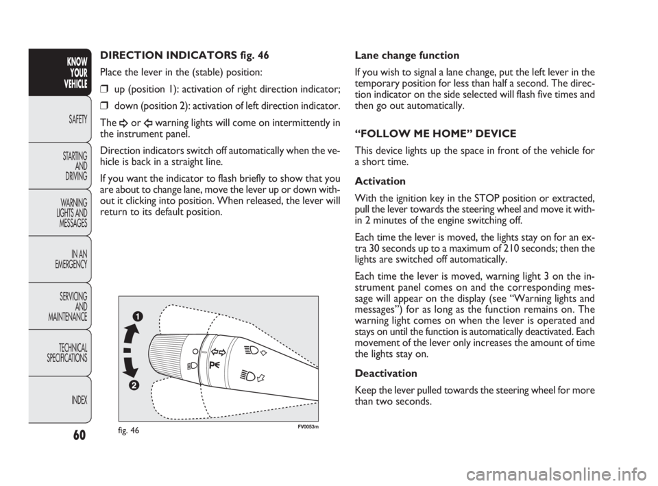
than two seconds. DIRECTION INDICATORS fig. 46
Place the lever in the (stable) position:
❒up (position 1): activation of right direction indicator;
❒down (position 2): activation of left direction indicator.
The
¥or Îwarning lights will come on intermittently in
the instrument panel.
Direction indicators switch off automatically when the ve-
hicle is back in a straight line.
If you want the indicator to flash briefly to show that you
are about to change lane, move the lever up or down with-
out it clicking into position. When released, the lever will
return to its default position.
035-114 DOBLO LUM EN 2e 7.0 21-05-2010 9:54 Pagina 60
Page 62 of 274
61
KNOW
YOUR
VEHICLE
SAFETY
STARTING
AND
DRIVING
WARNING
LIGHTS AND
MESSAGES
IN AN
EMERGENCY
SERVICING
AND
MAINTENANCE
TECHNICAL
SPECIFICATIONS
INDEX
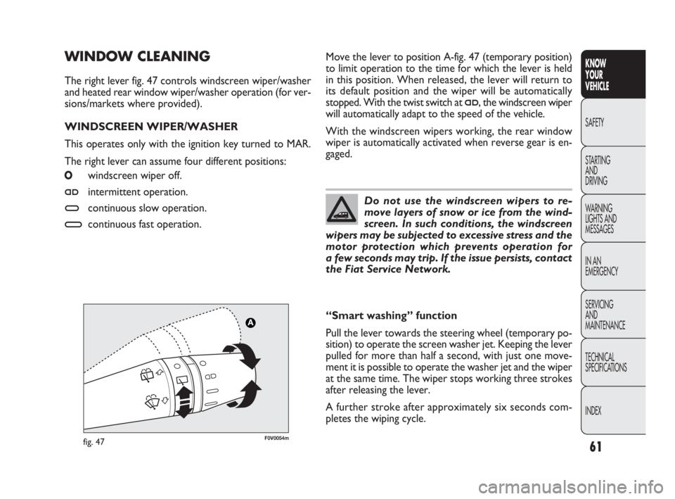
Move the lever to position A-fig. 47 (temporary position)
to limit operation to the time for which the lever is held
in this position. When released, the lever will return to
its default position and the wiper will be automatically
stopped. With the twist switch at
≤, the windscreen wiper
will automatically adapt to the speed of the vehicle.
With the windscreen wipers working, the rear window
wiper is automatically activated when reverse gear is en-
gaged.
WINDOW CLEANING
The right lever fig. 47 controls windscreen wiper/washer
and heated rear window wiper/washer operation (for ver-
sions/markets where provided).
WINDSCREEN WIPER/WASHER
This operates only with the ignition key turned to MAR.
The right lever can assume four different positions:
Owindscreen wiper off.
≤intermittent operation.
≥continuous slow operation.
¥continuous fast operation.
Do not use the windscreen wipers to re-
move layers of snow or ice from the wind-
screen. In such conditions, the windscreen
wipers may be subjected to excessive stress and the
motor protection which prevents operation for
a few seconds may trip. If the issue persists, contact
the Fiat Service Network.
“Smart washing” function
Pull the lever towards the steering wheel (temporary po-
sition) to operate the screen washer jet. Keeping the lever
pulled for more than half a second, with just one move-
ment it is possible to operate the washer jet and the wiper
at the same time. The wiper stops working three strokes
after releasing the lever.
A further stroke after approximately six seconds com-
pletes the wiping cycle.
F0V0054mfig. 47
035-114 DOBLO LUM EN 2e 7.0 21-05-2010 9:54 Pagina 61
Page 63 of 274
62
KNOW
YOUR
VEHICLE
SAFETY
STARTING
AND
DRIVING
WARNING
LIGHTS AND
MESSAGES
IN AN
EMERGENCY
SERVICING
AND
MAINTENANCE
TECHNICAL
SPECIFICATIONS
INDEX
REAR WINDOW WIPER/WASHER
(for versions/markets where provided)
This operates only with the ignition key turned to MAR.
Activation
Turn the twist switch to
'to operate the rear window
wiper:
❒in intermittent mode if the windscreen wiper is off;
❒synchronised operation (but with half-stroke frequen-
cy) when the windscreen wiper is on;
❒continuous operation with reverse engaged and func-
tion on.
With the windscreen wiper on and reverse gear engaged,
rear window wiping will be continuous.
Pushing the lever towards the dashboard (temporary po-
sition) will activate the rear window washer jet. Keeping
the lever pushed for more than half a second will also ac-
tivate the rear window wiper. Releasing the lever will ac-
tivate the smart washing function, as described for the
windscreen wiper.
Deactivation
The function stops when the lever is released.
Do not use the rear window wiper to re-
move layers of snow or ice. In such condi-
tions, the wiper may be subjected to ex-
cessive stress and the motor protection, which pre-
vents operation for a few seconds, may intervene.
If the issue persists, contact the Fiat Service Net-
work.
HEADLIGHT WASHERS
(for versions/markets where provided)
They are activated when the dipped headlamps are on and the
screen washer is activated.
WARNING Check jet function and cleanliness at regular
intervals.
The headlamp washer jet does not function
when the level of fluid in the reservoir falls
below 1.6 litres.
035-114 DOBLO LUM EN 2e 7.0 21-05-2010 9:54 Pagina 62
Page 64 of 274
63
KNOW
YOUR
VEHICLE
SAFETY
STARTING
AND
DRIVING
WARNING
LIGHTS AND
MESSAGES
IN AN
EMERGENCY
SERVICING
AND
MAINTENANCE
TECHNICAL
SPECIFICATIONS
INDEX
A A
B B
F0V0092mfig. 48
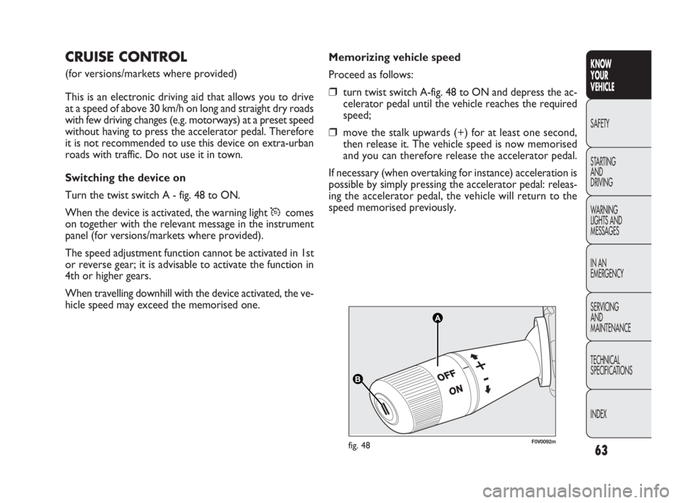
Memorizing vehicle speed
Proceed as follows:
❒turn twist switch A-fig. 48 to ON and depress the ac-
celerator pedal until the vehicle reaches the required
speed;
❒move the stalk upwards (+) for at least one second,
then release it. The vehicle speed is now memorised
and you can therefore release the accelerator pedal.
If necessary (when overtaking for instance) acceleration is
possible by simply pressing the accelerator pedal: releas-
ing the accelerator pedal, the vehicle will return to the
speed memorised previously.
CRUISE CONTROL
(for versions/markets where provided)
This is an electronic driving aid that allows you to drive
at a speed of above 30 km/h on long and straight dry roads
with few driving changes (e.g. motorways) at a preset speed
without having to press the accelerator pedal. Therefore
it is not recommended to use this device on extra-urban
roads with traffic. Do not use it in town.
Switching the device on
Turn the twist switch A - fig. 48 to ON.
When the device is activated, the warning light Ücomes
on together with the relevant message in the instrument
panel (for versions/markets where provided).
The speed adjustment function cannot be activated in 1st
or reverse gear; it is advisable to activate the function in
4th or higher gears.
When travelling downhill with the device activated, the ve-
hicle speed may exceed the memorised one.
035-114 DOBLO LUM EN 2e 7.0 21-05-2010 9:54 Pagina 63
Page 80 of 274
79
KNOW
YOUR
VEHICLE
SAFETY
STARTING
AND
DRIVING
WARNING
LIGHTS AND
MESSAGES
IN AN
EMERGENCY
SERVICING
AND
MAINTENANCE
TECHNICAL
SPECIFICATIONS
INDEX
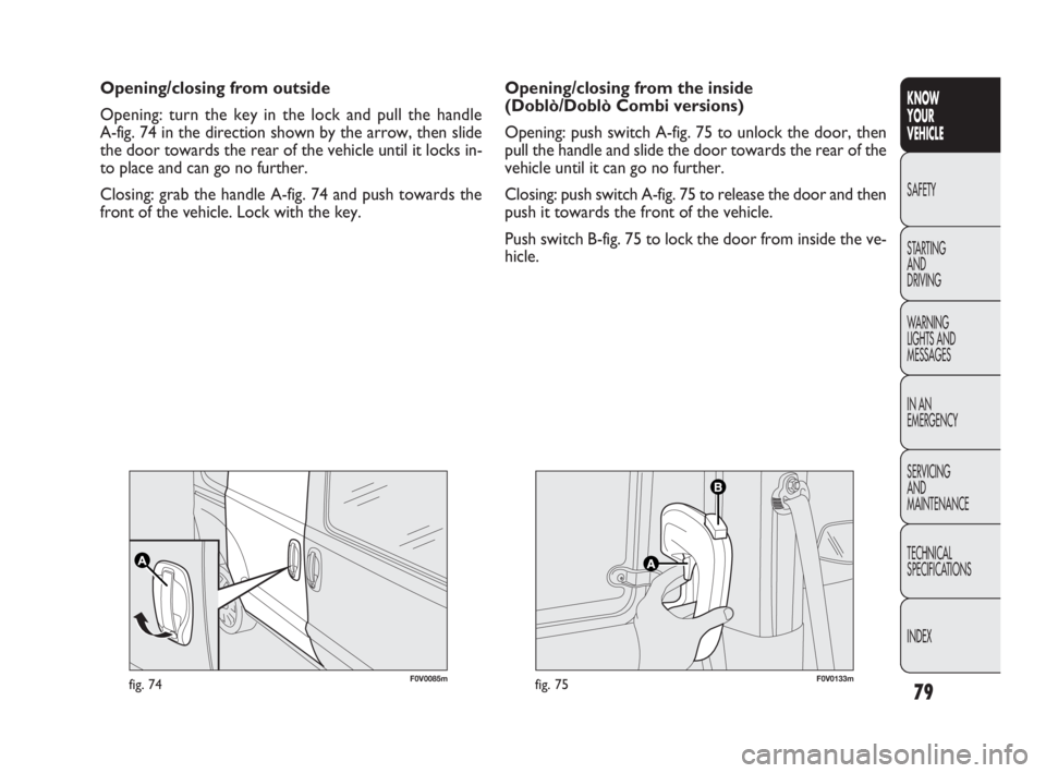
F0V0085mfig. 74F0V0133mfig. 75
Opening/closing from the inside
(Doblò/Doblò Combi versions)
Opening: push switch A-fig. 75 to unlock the door, then
pull the handle and slide the door towards the rear of the
vehicle until it can go no further.
Closing: push switch A-fig. 75 to release the door and then
push it towards the front of the vehicle.
Push switch B-fig. 75 to lock the door from inside the ve-
hicle. Opening/closing from outside
Opening: turn the key in the lock and pull the handle
A-fig. 74 in the direction shown by the arrow, then slide
the door towards the rear of the vehicle until it locks in-
to place and can go no further.
Closing: grab the handle A-fig. 74 and push towards the
front of the vehicle. Lock with the key.
035-114 DOBLO LUM EN 2e 7.0 21-05-2010 9:54 Pagina 79
Page 81 of 274
80
KNOW
YOUR
VEHICLE
SAFETY
STARTING
AND
DRIVING
WARNING
LIGHTS AND
MESSAGES
IN AN
EMERGENCY
SERVICING
AND
MAINTENANCE
TECHNICAL
SPECIFICATIONS
INDEX
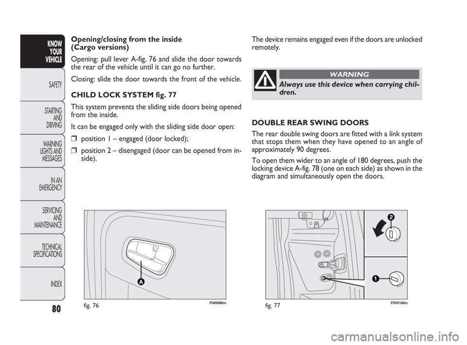
F0V0066mfig. 76F0V0186mfig. 77
The device remains engaged even if the doors are unlocked
remotely. Opening/closing from the inside
(Cargo versions)
Opening: pull lever A-fig. 76 and slide the door towards
the rear of the vehicle until it can go no further.
Closing: slide the door towards the front of the vehicle.
CHILD LOCK SYSTEM fig. 77
This system prevents the sliding side doors being opened
from the inside.
It can be engaged only with the sliding side door open:
❒position 1 – engaged (door locked);
❒position 2 – disengaged (door can be opened from in-
side).
Always use this device when carrying chil-
dren.
WARNING
DOUBLE REAR SWING DOORS
The rear double swing doors are fitted with a link system
that stops them when they have opened to an angle of
approximately 90 degrees.
To open them wider to an angle of 180 degrees, push the
locking device A-fig. 78 (one on each side) as shown in the
diagram and simultaneously open the doors.
035-114 DOBLO LUM EN 2e 7.0 21-05-2010 9:54 Pagina 80