technical specifications FIAT DOBLO COMBI 2011 Owner handbook (in English)
[x] Cancel search | Manufacturer: FIAT, Model Year: 2011, Model line: DOBLO COMBI, Model: FIAT DOBLO COMBI 2011Pages: 274, PDF Size: 5.96 MB
Page 141 of 274
140
KNOW
YOUR
VEHICLE
SAFETY
STARTING
AND
DRIVING
WARNING
LIGHTS AND
MESSAGES
IN AN
EMERGENCY
SERVICING
AND
MAINTENANCE
TECHNICAL
SPECIFICATIONS
INDEX
SNOW TYRES
A Fiat Dealership will be happy to provide advice con-
cerning the most suitable type of tyre for the customer’s
requirements.
For the type, pressures and specifications of the snow tyre
to be used, follow carefully the instructions given in the
“Wheels” paragraph of the “Technical specifications” sec-
tion.
The winter performance of these tyres is considerably re-
duced when the tread thickness is less than 4 mm. If this
is the case, replace them.
Due to their specific features, the performance of snow
tyres is much lower than that of standard tyres in normal
conditions or on long motorway stretches. You should
therefore use them only in the conditions for which they
were designed.
IMPORTANT When using snow tyres with a maximum
speed index below the one that can be reached by the
vehicle (increased by 5%), place a notice in the passenger
compartment, plainly in view, which states the maximum
speed allowed by the snow tyres (as per EC Directive).
All four tyres should be the same (brand and profile) to
ensure greater safety when driving and braking as well as
making the car more responsive.
Remember that you should not change the rotation di-
rection of the tyres.The ABS with which the vehicle may be
equipped will not control the braking sys-
tem of the trailer. Particular caution is therefore
required on slippery roads.
WARNING
Never modify the braking system of the ve-
hicle to control the trailer brake. The trail-
er braking system must be fully independent from
the hydraulic system of the vehicle.
WARNING
Page 142 of 274
141
KNOW
YOUR
VEHICLE
SAFETY
STARTING
AND
DRIVING
WARNING
LIGHTS AND
MESSAGES
IN AN
EMERGENCY
SERVICING
AND
MAINTENANCE
TECHNICAL
SPECIFICATIONS
INDEX
SNOW CHAINS
The use of snow chains should be in compliance with lo-
cal regulations.
Snow chains may be fitted only to the front wheel tyres
(drive wheels).
Check the tension of the chains after the first few metres
have been driven.You must not exceed 160 km/h on snow
tyres with a “Q” mark; in any case, make
sure you stick to the rules of the highway code.
WARNING
Keep your speed down when snow chains
are fitted – do not exceed 50 km/h. Avoid
potholes, steps and pavements and also
avoid driving for long distances on roads not cov-
ered with snow to avoid damaging the car and the
road surface.
Page 143 of 274
142
KNOW
YOUR
VEHICLE
SAFETY
STARTING
AND
DRIVING
WARNING
LIGHTS AND
MESSAGES
IN AN
EMERGENCY
SERVICING
AND
MAINTENANCE
TECHNICAL
SPECIFICATIONS
INDEX
❒sprinkle talcum powder on the rubber windscreen and
rear window wiper blades and lift them off the glass;
❒open the windows slightly;
❒cover the vehicle with a piece of fabric or perforated
plastic sheet; Do not use compact plastic tarpaulins,
which prevent humidity from evaporating from the sur-
face of the vehicle;
❒inflate tyres to a pressure of +0.5 bar above the nor-
mal specified pressure and check regularly;
❒do not drain the engine cooling system.
VEHICLE INACTIVITY
If the vehicle needs to be off the road for longer than one
month, the following precautions must be taken:
❒park the vehicle indoors in a dry and, if possible, well-
ventilated place;
❒engage a gear and check that the handbrake is not on;
❒disconnect the negative terminal from the battery pole
(see paragraph “Vehicle inactivity” in the "Dashboard
and controls" chapter) and check the charge conditions
(see paragraph “Battery” in the “Care and mainte-
nance” chapter);
❒clean and protect the painted parts using protective
wax;
❒clean and protect the shiny metal parts using special
compounds readily available;
Page 156 of 274
155
KNOW
YOUR
VEHICLE
SAFETY
STARTING
AND
DRIVING
WARNING
LIGHTS AND
MESSAGES
IN AN
EMERGENCY
SERVICING
AND
MAINTENANCE
TECHNICAL
SPECIFICATIONS
INDEX
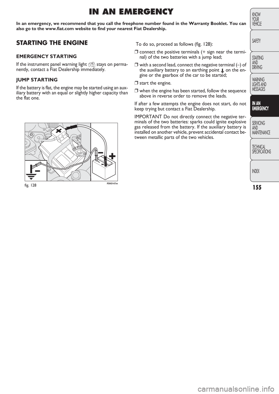
F0V0147mfig. 128
STARTING THE ENGINE
EMERGENCY STARTING
If the instrument panel warning light
Ystays on perma-
nently, contact a Fiat Dealership immediately.
JUMP STARTING
If the battery is flat, the engine may be started using an aux-
iliary battery with an equal or slightly higher capacity than
the flat one.
IN AN EMERGENCY
In an emergency, we recommend that you call the freephone number found in the Warranty Booklet. You can
also go to the www.fiat.com website to find your nearest Fiat Dealership.
To do so, proceed as follows (fig. 128):
❒connect the positive terminals (+ sign near the termi-
nal) of the two batteries with a jump lead;
❒with a second lead, connect the negative terminal (–) of
the auxiliary battery to an earthing point Eon the en-
gine or the gearbox of the car to be started;
❒start the engine.
❒when the engine has been started, follow the sequence
above in reverse order to remove the leads.
If after a few attempts the engine does not start, do not
keep trying but contact a Fiat Dealership.
IMPORTANT Do not directly connect the negative ter-
minals of the two batteries: sparks could ignite explosive
gas released from the battery. If the auxiliary battery is
installed on another vehicle, prevent accidental contact be-
tween metallic parts of the two vehicles.
Page 157 of 274
156
KNOW
YOUR
VEHICLE
SAFETY
STARTING
AND
DRIVING
WARNING
LIGHTS AND
MESSAGES
IN AN
EMERGENCY
SERVICING
AND
MAINTENANCE
TECHNICAL
SPECIFICATIONS
INDEX
Strictly avoid using a rapid battery charg-
er for jump starting: this could damage the
system electronics and the ignition and en-
gine supply control units.
This procedure must be performed by ex-
perts because incorrect actions may cause
considerable electrical discharge. Furthermore,
battery fluid is poisonous and corrosive: avoid con-
tact with skin and eyes. Keep naked flames and
lit cigarettes away from the battery. Do not cre-
ate sparks.
WARNING
BUMP STARTING
Never bump start the engine by pushing, towing or driving
downhill. This could cause fuel to flow into the catalytic
converter and damage it beyond repair.
IMPORTANT Remember that the brake booster and the
power steering system are not active until the engine is
started, so you will need to apply much more force to
the brake pedal or steering wheel.
CHANGING A TYRE
The vehicle is originally equipped with the Fix&Go auto-
matic quick tyre repair kit (see instructions in the next sec-
tion). As an alternative, the vehicle may have a normal-
sized spare wheel.
Wheel changing and correct use of the jack and spare
wheel call for some precautions, as listed below.
The spare wheel (where provided) is
specifically for your vehicle. Therefore, it
must not be used on other models. Do not use
spare wheels of other models on your vehicle. The
spare wheel should be used only in an emergency.
Use it as little as possible.
WARNING
Page 158 of 274
157
KNOW
YOUR
VEHICLE
SAFETY
STARTING
AND
DRIVING
WARNING
LIGHTS AND
MESSAGES
IN AN
EMERGENCY
SERVICING
AND
MAINTENANCE
TECHNICAL
SPECIFICATIONS
INDEX
Use your hazard lights, warning triangle,
etc to show that your car is stationary.
Passengers should get out of the car, particularly
if it is heavily loaded, and wait for the wheel to be
changed away from the traffic. If you are on a
steep slope or uneven surface, place wedges or
other suitable objects under the wheels to secure
the vehicle. Repair and refit the standard wheel
as soon as possible. Do not grease the bolt threads
before you fit them, because they could sudden-
ly come loose.
WARNING
Use the jack only to replace wheels on the
vehicle with which it is supplied or on oth-
er vehicles of the same model. Never use the jack
for other purposes, such as lifting other models.
Never use the jack to carry out repairs under the
vehicle. Incorrect positioning of the jack may
cause the lifted vehicle to fall. Do not use the jack
for loads higher than the one shown on its label.
WARNING
Incorrect hub cap assembly may cause it
to come off when the car is moving. Nev-
er tamper with the inflation valve. Never intro-
duce tools of any kind between the rim and the
tyre. Check tyre and spare wheel pressures regu-
larly, referring to the values shown in the “Tech-
nical specifications” section.
WARNING
Note for one-way tyres
One-way tyres have a few arrows on the side indicating
the rotation direction. If a wheel is changed (when punc-
tured, for example) the direction of the arrows on the spa-
re wheel tyre may not coincide with the rotation direc-
tion of the wheel to be replaced. In these conditions, too,
the tyre still maintains its safety features.
Anyway, it is recommended to have the wheel repaired
and refitted as soon as possible, as the best performance
is achieved when the rotation direction of all tyres coin-
cides with the one indicated by the arrows.
Page 159 of 274
F0V0148mfig. 130
F0V0149mfig. 129
158
KNOW
YOUR
VEHICLE
SAFETY
STARTING
AND
DRIVING
WARNING
LIGHTS AND
MESSAGES
IN AN
EMERGENCY
SERVICING
AND
MAINTENANCE
TECHNICAL
SPECIFICATIONS
INDEX
Important notes:
❒ the jack weighs 4 kg;
❒the jack requires no adjustment;
❒the jack cannot be repaired; if it breaks, it must be re-
placed with a new one of the same type;
❒no tool other than the cranking handle may be fitted on
the jack.
To change a tyre, proceed as follows:
❒stop the vehicle in a position where it is not a danger
for other traffic and where you can replace the wheel
safely. The ground should be flat and solid;
❒turn the engine off and engage the handbrake;
❒engage first gear or reverse;
❒wear the reflective safety jacket (compulsory by law)
before getting out of the vehicle;
❒ indicate that the vehicle is parked up by using the de-
vices required by law in the country in which you are
travelling (e.g. warning triangle, hazard lights etc.);
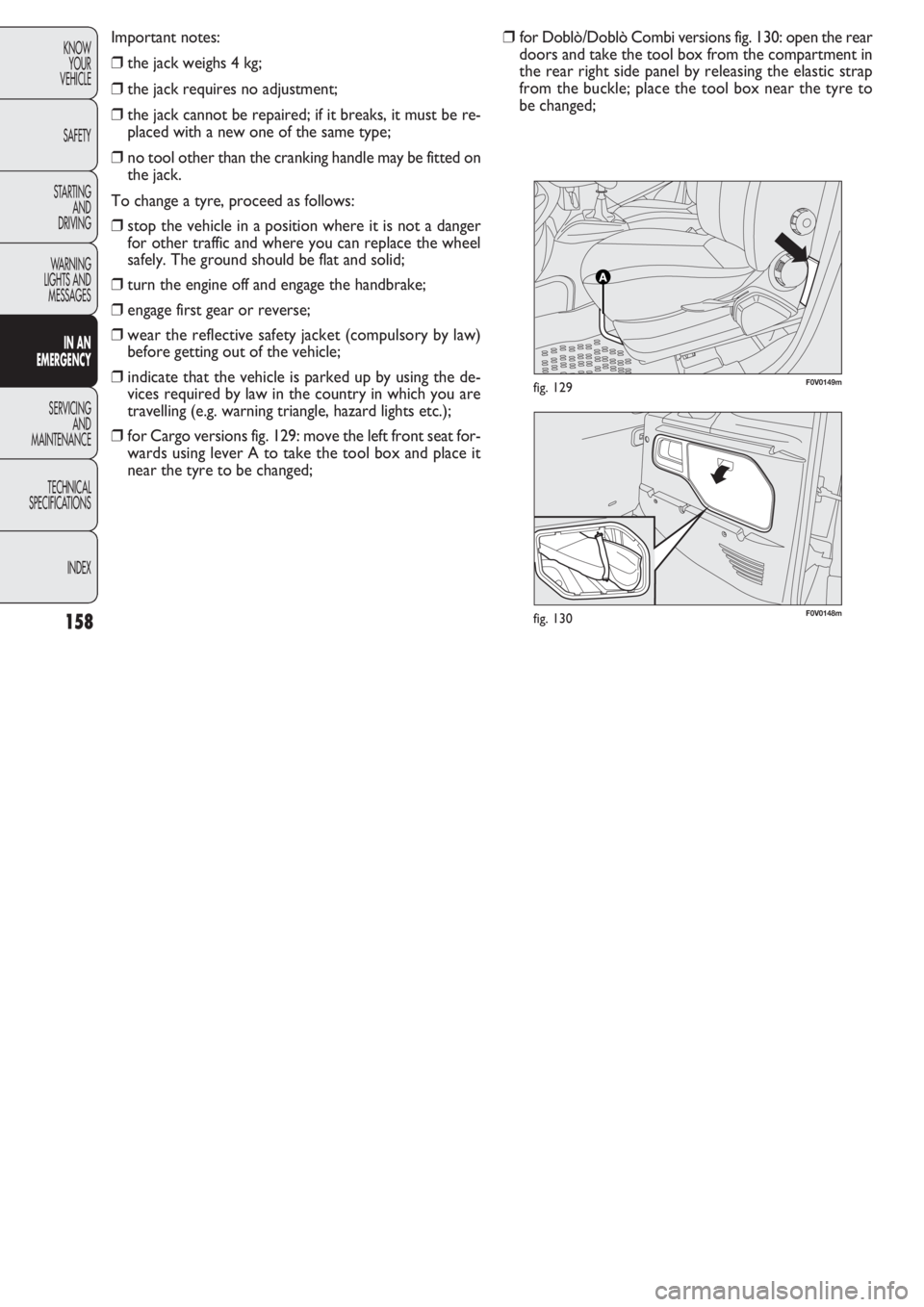
❒for Cargo versions fig. 129: move the left front seat for-
wards using lever A to take the tool box and place it
near the tyre to be changed;❒for Doblò/Doblò Combi versions fig. 130: open the rear
doors and take the tool box from the compartment in
the rear right side panel by releasing the elastic strap
from the buckle; place the tool box near the tyre to
be changed;
Page 160 of 274
159
KNOW
YOUR
VEHICLE
SAFETY
STARTING
AND
DRIVING
WARNING
LIGHTS AND
MESSAGES
IN AN
EMERGENCY
SERVICING
AND
MAINTENANCE
TECHNICAL
SPECIFICATIONS
INDEX
F0V0193mfig. 133
F0V0151mfig. 132
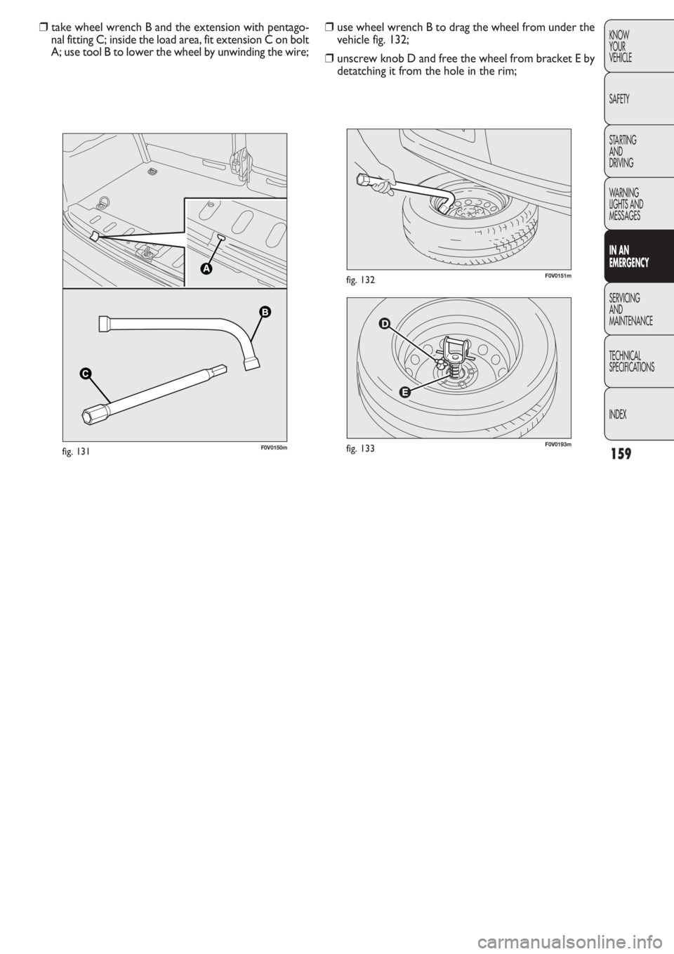
❒use wheel wrench B to drag the wheel from under the
vehicle fig. 132;
❒unscrew knob D and free the wheel from bracket E by
detatching it from the hole in the rim; ❒take wheel wrench B and the extension with pentago-
nal fitting C; inside the load area, fit extension C on bolt
A; use tool B to lower the wheel by unwinding the wire;
B B
C
C
F0V0150mfig. 131
Page 161 of 274
160
KNOW
YOUR
VEHICLE
SAFETY
STARTING
AND
DRIVING
WARNING
LIGHTS AND
MESSAGES
IN AN
EMERGENCY
SERVICING
AND
MAINTENANCE
TECHNICAL
SPECIFICATIONS
INDEX
F0V0153mfig. 134bF0V0155mfig. 136
F0V0154mfig. 135
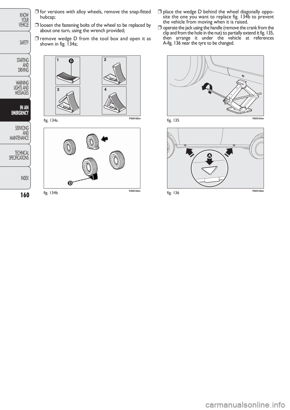
❒place the wedge D behind the wheel diagonally oppo-
site the one you want to replace fig. 134b to prevent
the vehicle from moving when it is raised.
❒
operate the jack using the handle (remove the crank from the
clip and from the hole in the nut) to partially extend it fig. 135,
then arrange it under the vehicle at references
A-fig. 136 near the tyre to be changed.
❒for versions with alloy wheels, remove the snap-fitted
hubcap;
❒loosen the fastening bolts of the wheel to be replaced by
about one turn, using the wrench provided;
❒remove wedge D from the tool box and open it as
shown in fig. 134a;
D
F0V0192mfig. 134a
Page 162 of 274

161
KNOW
YOUR
VEHICLE
SAFETY
STARTING
AND
DRIVING
WARNING
LIGHTS AND
MESSAGES
IN AN
EMERGENCY
SERVICING
AND
MAINTENANCE
TECHNICAL
SPECIFICATIONS
INDEX
F0V0156mfig. 137F0V0157mfig. 138
❒loosen the fastening bolts completely and then remove
the wheel;
❒make sure the contact surfaces between spare wheel
and hub are clean so that the fastening bolts will not
come loose;
❒fit the standard wheel by inserting the first bolt two
threads B-fig 138 into the hole closest to the inflation
valve A;
❒fit the hubcap, making sure that the symbol Caligns
with the inflation valve, and then insert the other three
bolts.
❒tighten the bolts using the wrench provided;
❒turn the jack handle to lower the vehicle, and remove
the jack;
❒use the wrench provided to tighten the bolts in a criss-
cross fashion in the order shown in fig. 139. ❒operate the jack with the handle and extend it so that
groove A-fig. 137 of the jack fits correctly onto lower
profile B on the sidemember;
❒warn anybody nearby that the vehicle is about to be lift-
ed. They must stay clear and not touch the vehicle un-
til it is back on the ground.
❒introduce the handle by pushing it into the hole in the
nut and into the plastic clip, operate the jack and lift the
vehicle until the wheel is a few centimetres off the
ground. When turning the crank, ensure that it rotates
freely in order to avoid grazing your hands against the
ground. The moving components of the jack (screws
and joints) can also cause injuries, so do not touch them.
Clean yourself thoroughly if you come into contact with
lubricating grease;