change light FIAT DOBLO COMBI 2011 Owner handbook (in English)
[x] Cancel search | Manufacturer: FIAT, Model Year: 2011, Model line: DOBLO COMBI, Model: FIAT DOBLO COMBI 2011Pages: 274, PDF Size: 5.96 MB
Page 155 of 274
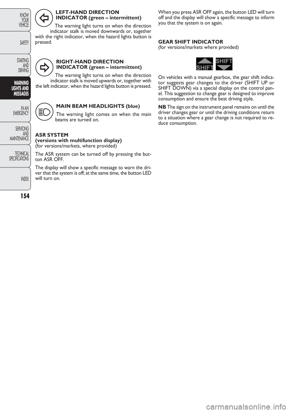
RIGHT-HAND DIRECTION
INDICATOR (green – intermittent)
The warning light turns on when the direction
indicator stalk is moved upwards or, together with
the left indicator, when the hazard lights button is pressed.
154
KNOW
YOUR
VEHICLE
SAFETY
STARTING
AND
DRIVING
WARNING
LIGHTS AND
MESSAGES
IN AN
EMERGENCY
SERVICING
AND
MAINTENANCE
TECHNICAL
SPECIFICA
TIONS
INDEX
LEFT-HAND DIRECTION
INDICATOR (green – intermittent)
The warning light turns on when the direction
indicator stalk is moved downwards or, together
with the right indicator, when the hazard lights button is
pressed.
MAIN BEAM HEADLIGHTS (blue)
The warning light comes on when the main
beams are turned on.
ASR SYSTEM
(versions with multifunction display)
(for versions/markets, where provided)
The ASR system can be turned off by pressing the but-
ton ASR OFF.
The display will show a specific message to warn the dri-
ver that the system is off; at the same time, the button LED
will turn on.
Î
¥
1
When you press ASR OFF again, the button LED will turn
off and the display will show a specific message to inform
you that the system is on again.
GEAR SHIFT INDICATOR
(for versions/markets where provided)
On vehicles with a manual gearbox, the gear shift indica-
tor suggests gear changes to the driver (SHIFT UP or
SHIFT DOWN) via a special display on the control pan-
el. This suggestion to change gear is designed to improve
consumption and ensure the best driving style.
NBThe sign on the instrument panel remains on until the
driver changes gear or until the driving conditions return
to a situation where a gear change is not required to re-
duce consumption.
Page 158 of 274
157
KNOW
YOUR
VEHICLE
SAFETY
STARTING
AND
DRIVING
WARNING
LIGHTS AND
MESSAGES
IN AN
EMERGENCY
SERVICING
AND
MAINTENANCE
TECHNICAL
SPECIFICATIONS
INDEX
Use your hazard lights, warning triangle,
etc to show that your car is stationary.
Passengers should get out of the car, particularly
if it is heavily loaded, and wait for the wheel to be
changed away from the traffic. If you are on a
steep slope or uneven surface, place wedges or
other suitable objects under the wheels to secure
the vehicle. Repair and refit the standard wheel
as soon as possible. Do not grease the bolt threads
before you fit them, because they could sudden-
ly come loose.
WARNING
Use the jack only to replace wheels on the
vehicle with which it is supplied or on oth-
er vehicles of the same model. Never use the jack
for other purposes, such as lifting other models.
Never use the jack to carry out repairs under the
vehicle. Incorrect positioning of the jack may
cause the lifted vehicle to fall. Do not use the jack
for loads higher than the one shown on its label.
WARNING
Incorrect hub cap assembly may cause it
to come off when the car is moving. Nev-
er tamper with the inflation valve. Never intro-
duce tools of any kind between the rim and the
tyre. Check tyre and spare wheel pressures regu-
larly, referring to the values shown in the “Tech-
nical specifications” section.
WARNING
Note for one-way tyres
One-way tyres have a few arrows on the side indicating
the rotation direction. If a wheel is changed (when punc-
tured, for example) the direction of the arrows on the spa-
re wheel tyre may not coincide with the rotation direc-
tion of the wheel to be replaced. In these conditions, too,
the tyre still maintains its safety features.
Anyway, it is recommended to have the wheel repaired
and refitted as soon as possible, as the best performance
is achieved when the rotation direction of all tyres coin-
cides with the one indicated by the arrows.
Page 159 of 274
F0V0148mfig. 130
F0V0149mfig. 129
158
KNOW
YOUR
VEHICLE
SAFETY
STARTING
AND
DRIVING
WARNING
LIGHTS AND
MESSAGES
IN AN
EMERGENCY
SERVICING
AND
MAINTENANCE
TECHNICAL
SPECIFICATIONS
INDEX
Important notes:
❒ the jack weighs 4 kg;
❒the jack requires no adjustment;
❒the jack cannot be repaired; if it breaks, it must be re-
placed with a new one of the same type;
❒no tool other than the cranking handle may be fitted on
the jack.
To change a tyre, proceed as follows:
❒stop the vehicle in a position where it is not a danger
for other traffic and where you can replace the wheel
safely. The ground should be flat and solid;
❒turn the engine off and engage the handbrake;
❒engage first gear or reverse;
❒wear the reflective safety jacket (compulsory by law)
before getting out of the vehicle;
❒ indicate that the vehicle is parked up by using the de-
vices required by law in the country in which you are
travelling (e.g. warning triangle, hazard lights etc.);
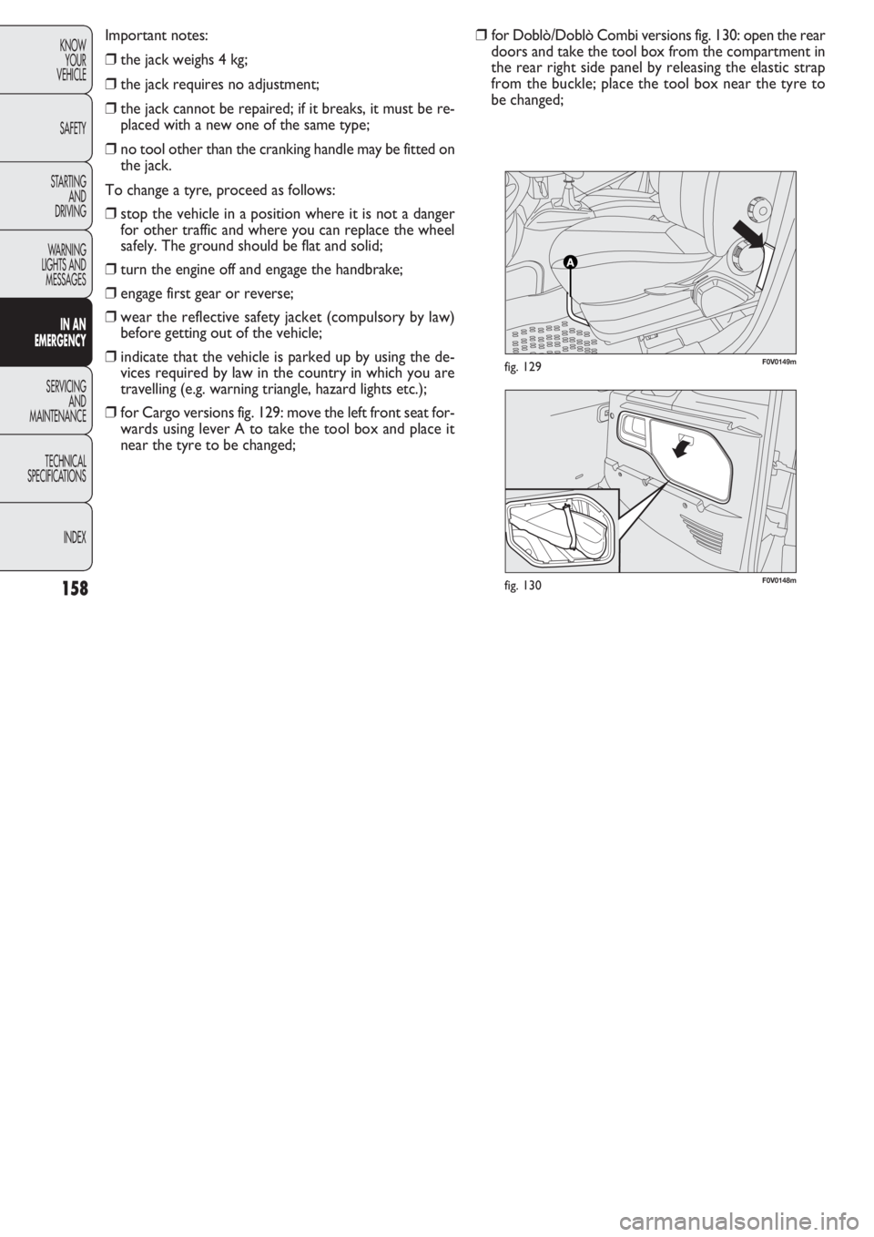
❒for Cargo versions fig. 129: move the left front seat for-
wards using lever A to take the tool box and place it
near the tyre to be changed;❒for Doblò/Doblò Combi versions fig. 130: open the rear
doors and take the tool box from the compartment in
the rear right side panel by releasing the elastic strap
from the buckle; place the tool box near the tyre to
be changed;
Page 161 of 274
160
KNOW
YOUR
VEHICLE
SAFETY
STARTING
AND
DRIVING
WARNING
LIGHTS AND
MESSAGES
IN AN
EMERGENCY
SERVICING
AND
MAINTENANCE
TECHNICAL
SPECIFICATIONS
INDEX
F0V0153mfig. 134bF0V0155mfig. 136
F0V0154mfig. 135
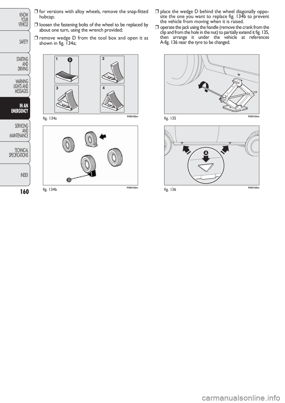
❒place the wedge D behind the wheel diagonally oppo-
site the one you want to replace fig. 134b to prevent
the vehicle from moving when it is raised.
❒
operate the jack using the handle (remove the crank from the
clip and from the hole in the nut) to partially extend it fig. 135,
then arrange it under the vehicle at references
A-fig. 136 near the tyre to be changed.
❒for versions with alloy wheels, remove the snap-fitted
hubcap;
❒loosen the fastening bolts of the wheel to be replaced by
about one turn, using the wrench provided;
❒remove wedge D from the tool box and open it as
shown in fig. 134a;
D
F0V0192mfig. 134a
Page 170 of 274
169
KNOW
YOUR
VEHICLE
SAFETY
STARTING
AND
DRIVING
WARNING
LIGHTS AND
MESSAGES
IN AN
EMERGENCY
SERVICING
AND
MAINTENANCE
TECHNICAL
SPECIFICATIONS
INDEX
CHANGING A BULB
GENERAL INSTRUCTIONS
❒Before changing a bulb, check the contacts for rusting;
❒burnt-out bulbs must be replaced by others of the same
type and wattage;
❒always check the direction of the beam after changing
a headlight bulb;
❒when a light is not working, check that the corre-
sponding fuse is intact before changing the bulb. For the
location of fuses, refer to the “Changing a fuse” para-
graph in this section.
Changes or repairs to the electrical system
carried out incorrectly and without due
consideration for the technical specifications of
the system can lead to malfunctioning and gen-
erate a fire hazard.
WARNING
Halogen lamps contain pressurised gas. If
they break, glass fragments could fly every-
where.
WARNING
Touch only the metal part of a halogen
lamp. Touching the transparent part of the
bulb with your fingers may reduce the in-
tensity of the emitted light and even reduce the
lifespan of the bulb. If you do touch it accidental-
ly, rub the bulb with an alcohol-soaked cloth and
leave to dry.
If possible, we recommend that you let
a Fiat Dealership replace the bulbs. Prop-
er operation and orientation of the exter-
nal lights are essential for driving safety and com-
plying with the law.
IMPORTANT The internal surface of the light may appear
slightly misty: this does not indicate a fault, and is actually
caused by low temperature and the degree of humidity
in the air. Misting will rapidly disappear when the head-
lights are switched on. The presence of drops inside the
headlights indicates infiltration of water. Go to a Fiat Deal-
ership.
Page 173 of 274
172
KNOW
YOUR
VEHICLE
SAFETY
STARTING
AND
DRIVING
WARNING
LIGHTS AND
MESSAGES
IN AN
EMERGENCY
SERVICING
AND
MAINTENANCE
TECHNICAL
SPECIFICATIONS
INDEX
F0V0028mfig. 150F0V0029mfig. 151
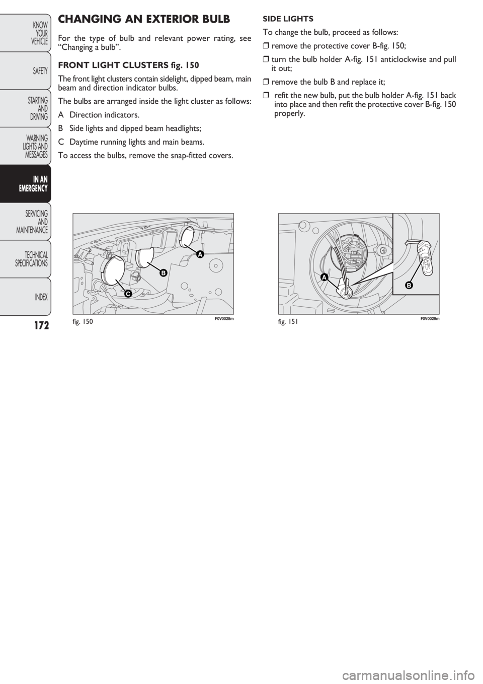
CHANGING AN EXTERIOR BULB
For the type of bulb and relevant power rating, see
“Changing a bulb”.
FRONT LIGHT CLUSTERS fig. 150
The front light clusters contain sidelight, dipped beam, main
beam and direction indicator bulbs.
The bulbs are arranged inside the light cluster as follows:
A Direction indicators.
B Side lights and dipped beam headlights;
C Daytime running lights and main beams.
To access the bulbs, remove the snap-fitted covers.
SIDE LIGHTS
To change the bulb, proceed as follows:
❒remove the protective cover B-fig. 150;
❒turn the bulb holder A-fig. 151 anticlockwise and pull
it out;
❒remove the bulb B and replace it;
❒refit the new bulb, put the bulb holder A-fig. 151 back
into place and then refit the protective cover B-fig. 150
properly.
Page 174 of 274
173
KNOW
YOUR
VEHICLE
SAFETY
STARTING
AND
DRIVING
WARNING
LIGHTS AND
MESSAGES
IN AN
EMERGENCY
SERVICING
AND
MAINTENANCE
TECHNICAL
SPECIFICATIONS
INDEX
F0V0030mfig. 152F0V0031mfig. 153
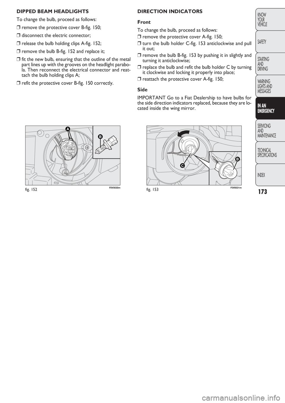
DIRECTION INDICATORS
Front
To change the bulb, proceed as follows:
❒remove the protective cover A-fig. 150;
❒turn the bulb holder C-fig. 153 anticlockwise and pull
it out;
❒remove the bulb B-fig. 153 by pushing it in slightly and
turning it anticlockwise;
❒replace the bulb and refit the bulb holder C by turning
it clockwise and locking it properly into place;
❒reattach the protective cover A-fig. 150;
Side
IMPORTANT Go to a Fiat Dealership to have bulbs for
the side direction indicators replaced, because they are lo-
cated inside the wing mirror. DIPPED BEAM HEADLIGHTS
To change the bulb, proceed as follows:
❒remove the protective cover B-fig. 150;
❒disconnect the electric connector;
❒release the bulb holding clips A-fig. 152;
❒remove the bulb B-fig. 152 and replace it;
❒fit the new bulb, ensuring that the outline of the metal
part lines up with the grooves on the headlight parabo-
la. Then reconnect the electrical connector and reat-
tach the bulb holding clips A;
❒refit the protective cover B-fig. 150 correctly.
Page 175 of 274

174
KNOW
YOUR
VEHICLE
SAFETY
STARTING
AND
DRIVING
WARNING
LIGHTS AND
MESSAGES
IN AN
EMERGENCY
SERVICING
AND
MAINTENANCE
TECHNICAL
SPECIFICATIONS
INDEX
F0V0032mfig. 154F0V0033mfig. 155
DAYTIME RUNNING LIGHTS
To change the bulb, proceed as follows:
❒remove the protective cover C-fig. 150;
❒turn the bulb holder E-fig. 155 anticlockwise and pull
it out;
❒remove the snap-fitted bulb;
❒replace the bulb and refit the bulb holder E by turning
it clockwise and locking it properly into place;
❒reattach the protective cover C-fig. 150;
FRONT FOG LIGHTS
(for versions/markets where provided)
IMPORTANT Go to a Fiat Dealership to have the front
fog light bulbs replaced. MAIN BEAM HEADLIGHTS
To change the bulb, proceed as follows:
❒remove the protective cover C-fig. 150;
❒disconnect the electric connector;
❒release the bulb holding clips D-fig. 154;
❒remove the bulb and replace it;
❒fit the new bulb, ensuring that the outline of the metal
part lines up with the grooves on the headlight parabo-
la. Then reconnect the electrical connector and reat-
tach the bulb holding clips D;
❒refit the protective cover C-fig. 150 correctly.
Page 176 of 274
175
KNOW
YOUR
VEHICLE
SAFETY
STARTING
AND
DRIVING
WARNING
LIGHTS AND
MESSAGES
IN AN
EMERGENCY
SERVICING
AND
MAINTENANCE
TECHNICAL
SPECIFICATIONS
INDEX
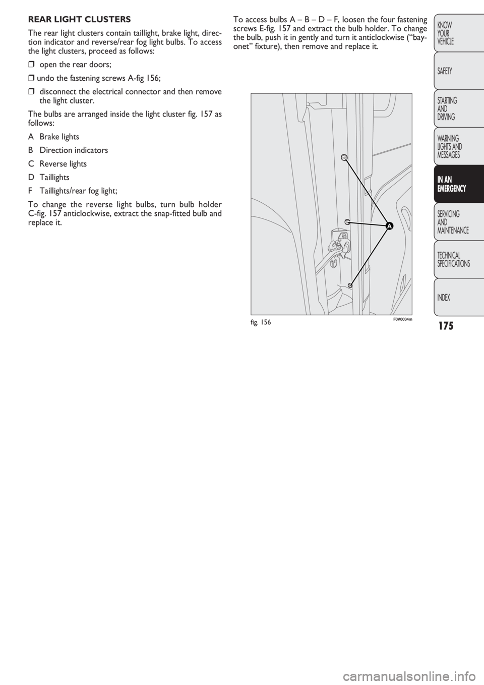
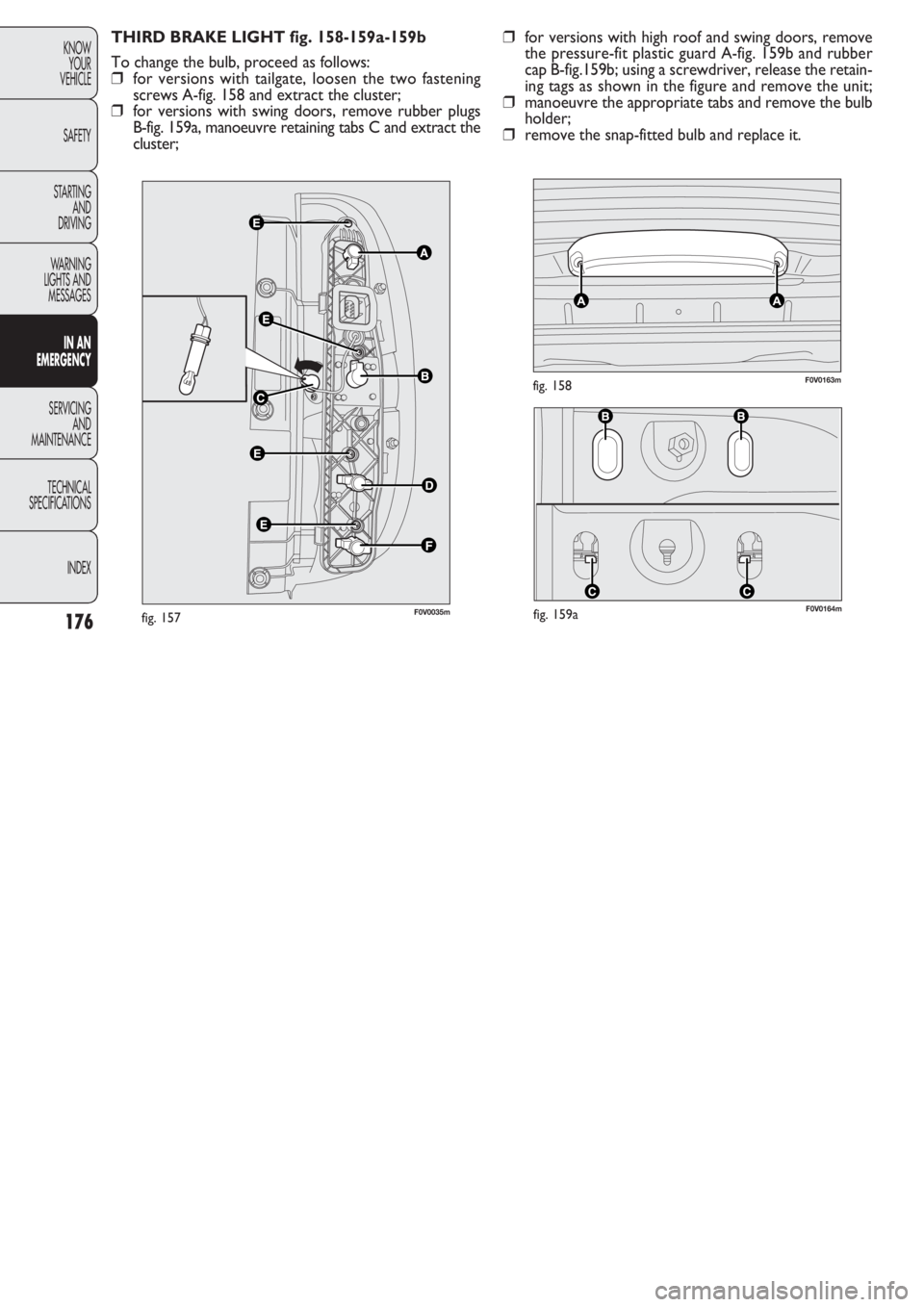
To access bulbs A – B – D – F, loosen the four fastening
screws E-fig. 157 and extract the bulb holder. To change
the bulb, push it in gently and turn it anticlockwise (“bay-
onet” fixture), then remove and replace it. REAR LIGHT CLUSTERS
The rear light clusters contain taillight, brake light, direc-
tion indicator and reverse/rear fog light bulbs. To access
the light clusters, proceed as follows:
❒open the rear doors;
❒undo the fastening screws A-fig 156;
❒disconnect the electrical connector and then remove
the light cluster.
The bulbs are arranged inside the light cluster fig. 157 as
follows:
A Brake lights
B Direction indicators
C Reverse lights
D Taillights
F Taillights/rear fog light;
To change the reverse light bulbs, turn bulb holder
C-fig. 157 anticlockwise, extract the snap-fitted bulb and
replace it.
F0V0034mfig. 156
Page 177 of 274
F0V0164mfig. 159a
F0V0163mfig. 158
176
KNOW
YOUR
VEHICLE
SAFETY
STARTING
AND
DRIVING
WARNING
LIGHTS AND
MESSAGES
IN AN
EMERGENCY
SERVICING
AND
MAINTENANCE
TECHNICAL
SPECIFICATIONS
INDEX
THIRD BRAKE LIGHT fig. 158-159a-159b
To change the bulb, proceed as follows:
❒for versions with tailgate, loosen the two fastening
screws A-fig. 158 and extract the cluster;
❒for versions with swing doors, remove rubber plugs
B-fig. 159a, manoeuvre retaining tabs C and extract the
cluster;❒for versions with high roof and swing doors, remove
the pressure-fit plastic guard A-fig. 159b and rubber
cap B-fig.159b; using a screwdriver, release the retain-
ing tags as shown in the figure and remove the unit;
❒manoeuvre the appropriate tabs and remove the bulb
holder;
❒remove the snap-fitted bulb and replace it.
F0V0035mfig. 157