technical specifications FIAT DOBLO COMBI 2012 Owner handbook (in English)
[x] Cancel search | Manufacturer: FIAT, Model Year: 2012, Model line: DOBLO COMBI, Model: FIAT DOBLO COMBI 2012Pages: 283, PDF Size: 6.31 MB
Page 37 of 283
33
KNOW
YOUR
VEHICLE
SAFETY
STAR
TING
AND
DRIVING
WARNING
LIGHTS AND
MESSAGES
IN AN
EMERGENCY
SERVICING
AND
MAINTENANCE
TECHNICAL
SPECIFICATIONS
INDEX
F0V0143mfig. 23
F0V0144mfig. 24
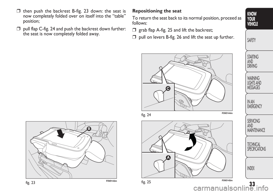
❒then push the backrest B-fig. 23 down: the seat is
now completely folded over on itself into the “table”
position;
❒pull flap C-fig. 24 and push the backrest down further:
the seat is now completely folded away. Repositioning the seat
To return the seat back to its normal position, proceed as
follows:❒grab flap A-fig. 25 and lift the backrest;
❒pull on levers B-fig. 26 and lift the seat up further.
F0V0145mfig. 25
Page 38 of 283
34
KNOWYOUR
VEHICLE
SAFETY
ST AR
TINGAND
DRIVING
WARNING
LIGHTS AND MESSAGES
IN AN
EMERGENCY
SERVICING AND
MAINTENANCE
TECHNICAL
SPECIFICATIONS
INDEX
F0V0146mfig. 26
When the passenger seat is folded away,
the space created cannot be used for load-
ing. When the vehicle is in motion, you are there-
fore advised to remove or secure any objects that
might interfere with the driver. If there is no par-
tition between the cab and the load compartment,
tall objects or packages may take up part of the
passenger area. Make sure that these items are
well secured by using the available hooks and that
they cannot interfere with the driver.
WARNING
ACCESS TO THE REAR SEATS
(Doblò and Doblò Combi versions)
To access the rear seats, open one of the sliding side doors
(see “Doors” in this section).
SEAT THAT CAN BE FOLDED INTO TABLE
(Doblò and Doblò Combi versions, where provided)
On some versions the seat can be folded into a table po-
sition. Completely retract the seat in table position for a total fold-
ing down avoiding interference with the dashboard.
WARNING Only move the seat when there are no rear
passengers.
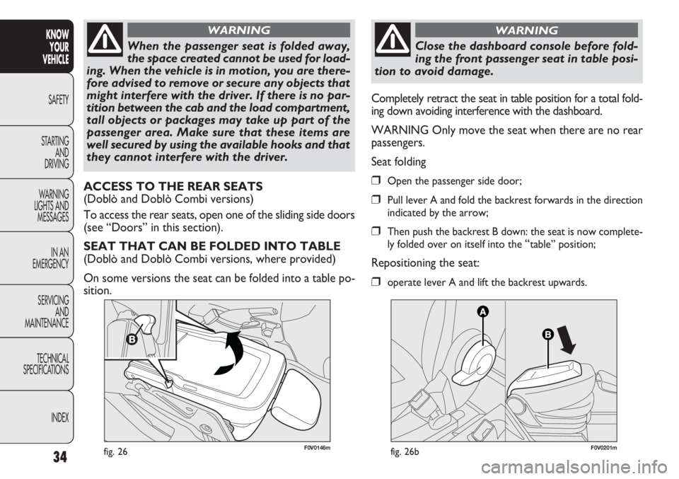
Seat folding❒Open the passenger side door;
❒Pull lever A and fold the backrest forwards in the direction
indicated by the arrow;
❒Then push the backrest B down: the seat is now complete-
ly folded over on itself into the
“table” position;
Repositioning the seat:
❒operate lever A and lift the backrest upwards.
F0V0201mfig. 26b
Close the dashboard console before fold-
ing the front passenger seat in table posi-
tion to avoid damage.
WARNING
Page 39 of 283
35
KNOW
YOUR
VEHICLE
SAFETY
STAR
TING
AND
DRIVING
WARNING
LIGHTS AND
MESSAGES
IN AN
EMERGENCY
SERVICING
AND
MAINTENANCE
TECHNICAL
SPECIFICATIONS
INDEX
3rdROW SEAT MOVEMENTS
Proceed as follows:
❒fully lower the rear seat head restraints;
❒move the seat belt to the side, making sure that it is
fully extended and not twisted;
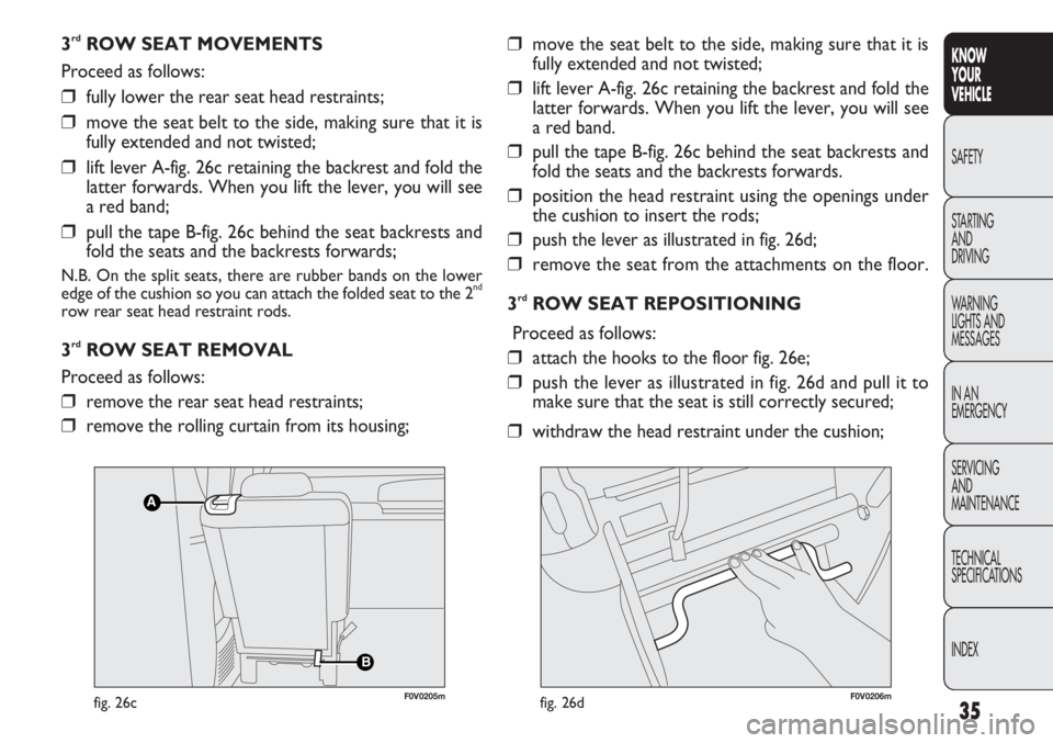
❒lift lever A-fig. 26c retaining the backrest and fold the
latter forwards. When you lift the lever, you will see
a red band;
❒pull the tape B-fig. 26c behind the seat backrests and
fold the seats and the backrests forwards;
N.B. On the split seats, there are rubber bands on the lower
edge of the cushion so you can attach the folded seat to the 2nd
row rear seat head restraint rods.
3rdROW SEAT REMOVAL
Proceed as follows:
❒remove the rear seat head restraints;
❒remove the rolling curtain from its housing;
❒move the seat belt to the side, making sure that it is
fully extended and not twisted;
❒lift lever A-fig. 26c retaining the backrest and fold the
latter forwards. When you lift the lever, you will see
a red band.
❒pull the tape B-fig. 26c behind the seat backrests and
fold the seats and the backrests forwards.
❒position the head restraint using the openings under
the cushion to insert the rods;
❒push the lever as illustrated in fig. 26d;
❒remove the seat from the attachments on the floor.
3
rdROW SEAT REPOSITIONING
Proceed as follows:
❒attach the hooks to the floor fig. 26e;
❒push the lever as illustrated in fig. 26d and pull it to
make sure that the seat is still correctly secured;
❒withdraw the head restraint under the cushion;
B
A
F0V0205mfig. 26cF0V0206mfig. 26d
Page 40 of 283
PARTITIONS
(for versions/markets where provided)
CARGO VERSIONS
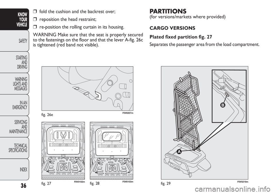
Plated fixed partition fig. 27
Separates the passenger area from the load compartment.
36
KNOWYOUR
VEHICLE
SAFETY
ST AR
TING AND
DRIVING
WARNING
LIGHTS AND MESSAGES
IN AN
EMERGENCY
SERVICING AND
MAINTENANCE
TECHNICAL
SPECIFICATIONS
INDEX
❒fold the cushion and the backrest over;
❒reposition the head restraint;
❒re-position the rolling curtain in its housing.
WARNING Make sure that the seat is properly secured
to the fastenings on the floor and that the lever A-fig. 26c
is tightened (red band not visible).
F0V0219mfig. 29F0V0103mfig. 28F0V0102mfig. 27
F0V0207mfig. 26e
Page 41 of 283
37
KNOW
YOUR
VEHICLE
SAFETY
STAR
TING
AND
DRIVING
WARNING
LIGHTS AND
MESSAGES
IN AN
EMERGENCY
SERVICING
AND
MAINTENANCE
TECHNICAL
SPECIFICATIONS
INDEX
F0V0170mfig. 31
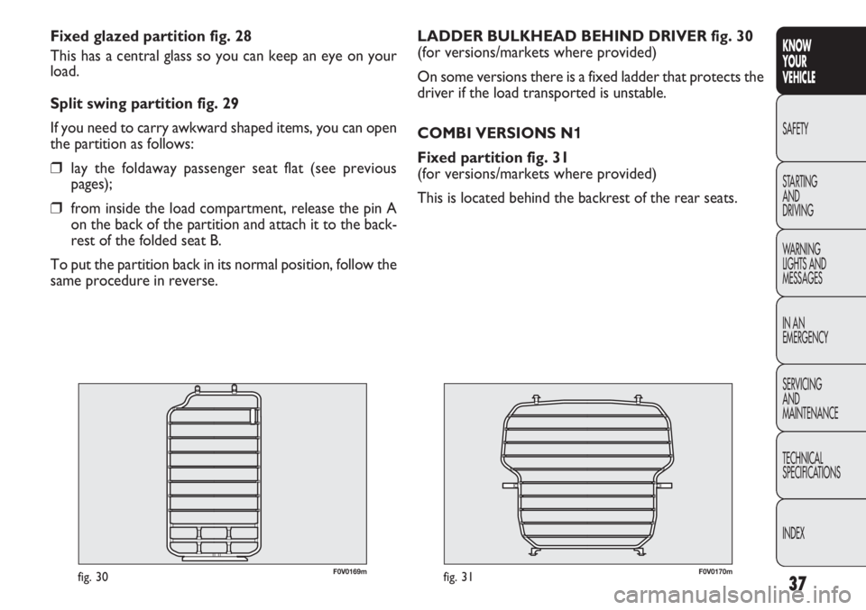
LADDER BULKHEAD BEHIND DRIVER fig. 30
(for versions/markets where provided)
On some versions there is a fixed ladder that protects the
driver if the load transported is unstable.
COMBI VERSIONS N1
Fixed partition fig. 31
(for versions/markets where provided)
This is located behind the backrest of the rear seats.
F0V0169mfig. 30
Fixed glazed partition fig. 28
This has a central glass so you can keep an eye on your
load.
Split swing partition fig. 29
If you need to carry awkward shaped items, you can open
the partition as follows:
❒lay the foldaway passenger seat flat (see previous
pages);
❒from inside the load compartment, release the pin A
on the back of the partition and attach it to the back-
rest of the folded seat B.
To put the partition back in its normal position, follow the
same procedure in reverse.
Page 42 of 283
38
KNOWYOUR
VEHICLE
SAFETY
ST AR
TING AND
DRIVING
WARNING
LIGHTS AND MESSAGES
IN AN
EMERGENCY
SERVICING AND
MAINTENANCE
TECHNICAL
SPECIFICATIONS
INDEX
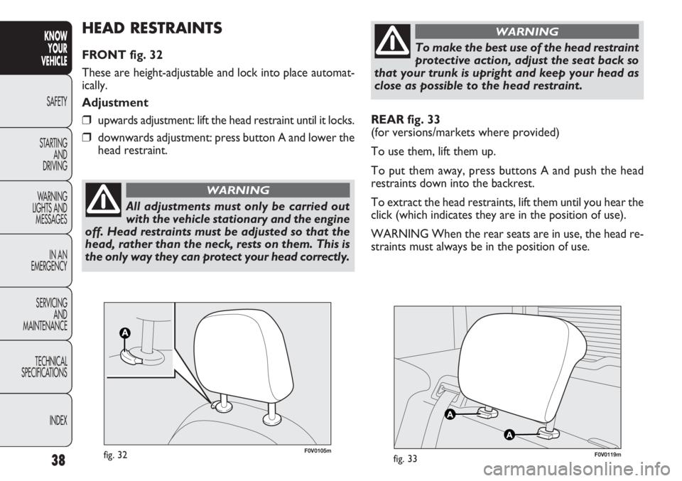
REAR fig. 33
(for versions/markets where provided)
To use them, lift them up.
To put them away, press buttons A and push the head
restraints down into the backrest.
To extract the head restraints, lift them until you hear the
click (which indicates they are in the position of use).
WARNING When the rear seats are in use, the head re-
straints must always be in the position of use.
F0V0119mfig. 33F0V0105mfig. 32
HEAD RESTRAINTS
FRONT fig. 32
These are height-adjustable and lock into place automat-
ically.
Adjustment
❒upwards adjustment: lift the head restraint until it locks.
❒downwards adjustment: press button A and lower the
head restraint.
All adjustments must only be carried out
with the vehicle stationary and the engine
off. Head restraints must be adjusted so that the
head, rather than the neck, rests on them. This is
the only way they can protect your head correctly.
WARNING
To make the best use of the head restraint
protective action, adjust the seat back so
that your trunk is upright and keep your head as
close as possible to the head restraint.
WARNING
Page 43 of 283
39
KNOW
YOUR
VEHICLE
SAFETY
STAR
TING
AND
DRIVING
WARNING
LIGHTS AND
MESSAGES
IN AN
EMERGENCY
SERVICING
AND
MAINTENANCE
TECHNICAL
SPECIFICATIONS
INDEX
F0V0014mfig. 34
STEERING WHEEL
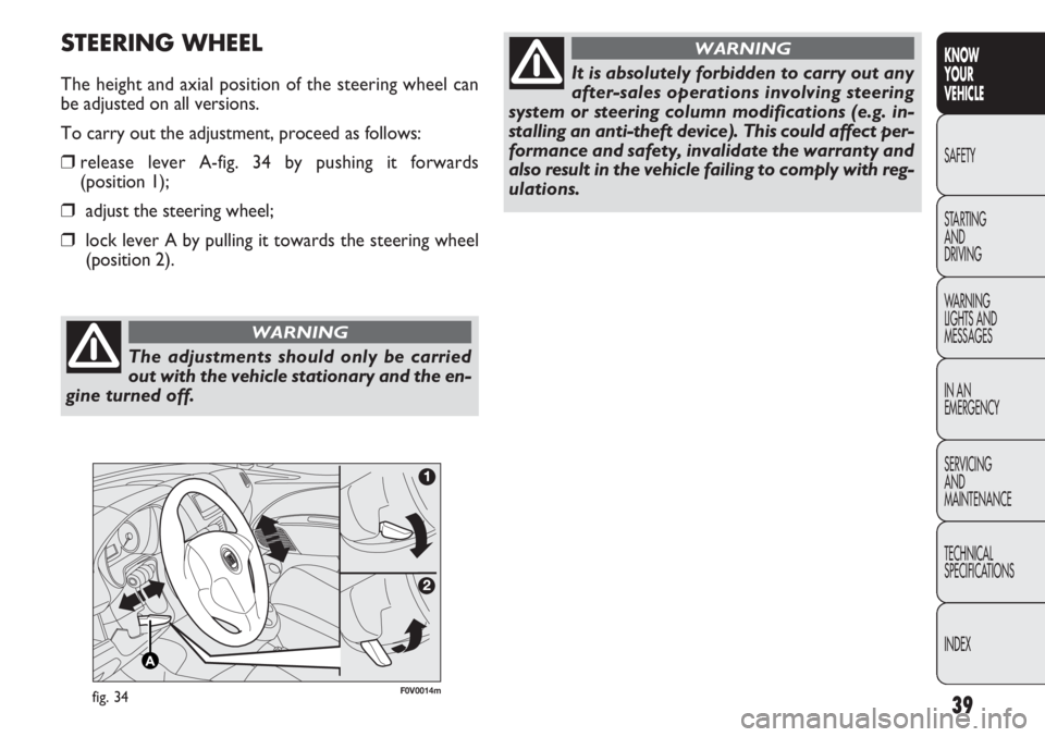
The height and axial position of the steering wheel can
be adjusted on all versions.
To carry out the adjustment, proceed as follows:
❒release lever A-fig. 34 by pushing it forwards
(position 1);
❒adjust the steering wheel;
❒lock lever A by pulling it towards the steering wheel
(position 2).
The adjustments should only be carried
out with the vehicle stationary and the en-
gine turned off.
WARNING
It is absolutely forbidden to carry out any
after-sales operations involving steering
system or steering column modifications (e.g. in-
stalling an anti-theft device). This could affect per-
formance and safety, invalidate the warranty and
also result in the vehicle failing to comply with reg-
ulations.
WARNING
Page 44 of 283
40
KNOWYOUR
VEHICLE
SAFETY
ST AR
TING AND
DRIVING
WARNING
LIGHTS AND MESSAGES
IN AN
EMERGENCY
SERVICING AND
MAINTENANCE
TECHNICAL
SPECIFICATIONS
INDEX
F0V0125mfig. 35F0V0084mfig. 36
REAR VIEW MIRRORS
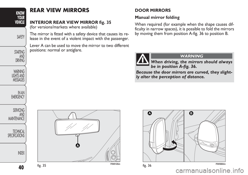
INTERIOR REAR VIEW MIRROR fig. 35
(for versions/markets where available)
The mirror is fitted with a safety device that causes its re-
lease in the event of a violent impact with the passenger.
Lever A can be used to move the mirror to two different
positions: normal or antiglare.
When driving, the mirrors should always
be in position A-fig. 36.
Because the door mirrors are curved, they slight-
ly alter the perception of distance.
WARNING
DOOR MIRRORS
Manual mirror folding
When required (for example when the shape causes dif-
ficulty in narrow spaces), it is possible to fold the mirrors
by moving them from position A-fig. 36 to position B.
Page 45 of 283
41
KNOW
YOUR
VEHICLE
SAFETY
STAR
TING
AND
DRIVING
WARNING
LIGHTS AND
MESSAGES
IN AN
EMERGENCY
SERVICING
AND
MAINTENANCE
TECHNICAL
SPECIFICATIONS
INDEX
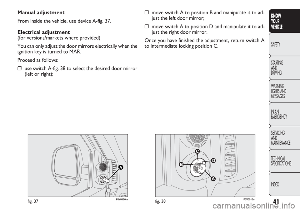
Manual adjustment
From inside the vehicle, use device A-fig. 37.
Electrical adjustment
(for versions/markets where provided)
You can only adjust the door mirrors electrically when the
ignition key is turned to MAR.
Proceed as follows:
❒use switch A-fig. 38 to select the desired door mirror
(left or right);
❒move switch A to position B and manipulate it to ad-
just the left door mirror;
❒move switch A to position D and manipulate it to ad-
just the right door mirror.
Once you have finished the adjustment, return switch A
to intermediate locking position C.
F0V0120mfig. 37F0V0015mfig. 38
Page 46 of 283
42
KNOWYOUR
VEHICLE
SAFETY
ST AR
TING AND
DRIVING
WARNING
LIGHTS AND MESSAGES
IN AN
EMERGENCY
SERVICING AND
MAINTENANCE
TECHNICAL
SPECIFICATIONS
INDEX
fig. 39F0V0016m
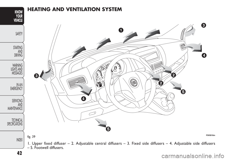
HEATING AND VENTILATION SYSTEM
1. Upper fixed diffuser – 2. Adjustable central diffusers – 3. Fixed side diffusers – 4. Adjustable side diffusers
– 5. Footwell diffusers.