FIAT DOBLO COMBI 2013 Owner handbook (in English)
Manufacturer: FIAT, Model Year: 2013, Model line: DOBLO COMBI, Model: FIAT DOBLO COMBI 2013Pages: 283, PDF Size: 6.31 MB
Page 91 of 283
87
KNOW
YOUR
VEHICLE
SAFETY
STAR
TING
AND
DRIVING
WARNING
LIGHTS AND
MESSAGES
IN AN
EMERGENCY
SERVICING
AND
MAINTENANCE
TECHNICAL
SPECIFICATIONS
INDEX
or
âť’open the sliding side door (Cargo versions);
âť’use device A-fig. 86 located on the inside of the right-
hand swing door;
âť’open the left-hand swing door by pulling on its handle
(see “Doors” in this section).
If you are travelling in areas with few re-
fuelling stations and you want to transport
fuel in a spare tank, comply with the law by us-
ing only an approved, suitably secured tank. Even
then, you are still increasing the risk of fire in an
accident.
WARNING
Never exceed the maximum allowed load
in the boot (see “Technical Specifications”).
Make sure that objects are well arranged in the
boot so that they do not project forwards and in-
jure passengers in the event of sudden braking.
WARNING
Page 92 of 283
F0V0136mfig. 87F0V0137mfig. 88
REMOVING THE PARCEL SHELF
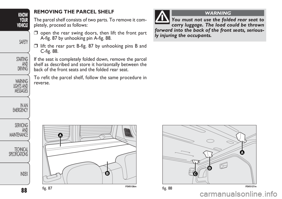
The parcel shelf consists of two parts. To remove it com-
pletely, proceed as follows:
âť’open the rear swing doors, then lift the front part
A-fig. 87 by unhooking pin A-fig. 88.
âť’lift the rear part B-fig. 87 by unhooking pins B and
C-fig. 88.
If the seat is completely folded down, remove the parcel
shelf as described and store it horizontally between the
back of the front seats and the folded rear seat.
To refit the parcel shelf, follow the same procedure in
reverse.
88
KNOW YOUR
VEHICLE
SAFETY
ST AR
TING AND
DRIVING
WARNING
LIGHTS AND MESSAGES
IN AN
EMERGENCY
SERVICING AND
MAINTENANCE
TECHNICAL
SPECIFICATIONS
INDEX
You must not use the folded rear seat to
carry luggage. The load could be thrown
forward into the back of the front seats, serious-
ly injuring the occupants.
WARNING
Page 93 of 283
89
KNOW
YOUR
VEHICLE
SAFETY
STAR
TING
AND
DRIVING
WARNING
LIGHTS AND
MESSAGES
IN AN
EMERGENCY
SERVICING
AND
MAINTENANCE
TECHNICAL
SPECIFICATIONS
INDEX
F0V0127mfig. 89a
EXTENDING THE BOOT
Proceed as follows:
âť’open the rear doors and remove the parcel shelf (as
described previously);
âť’fully lower the rear seat head restraints;
âť’move the seat belt to the side, making sure that it is
fully extended and not twisted;
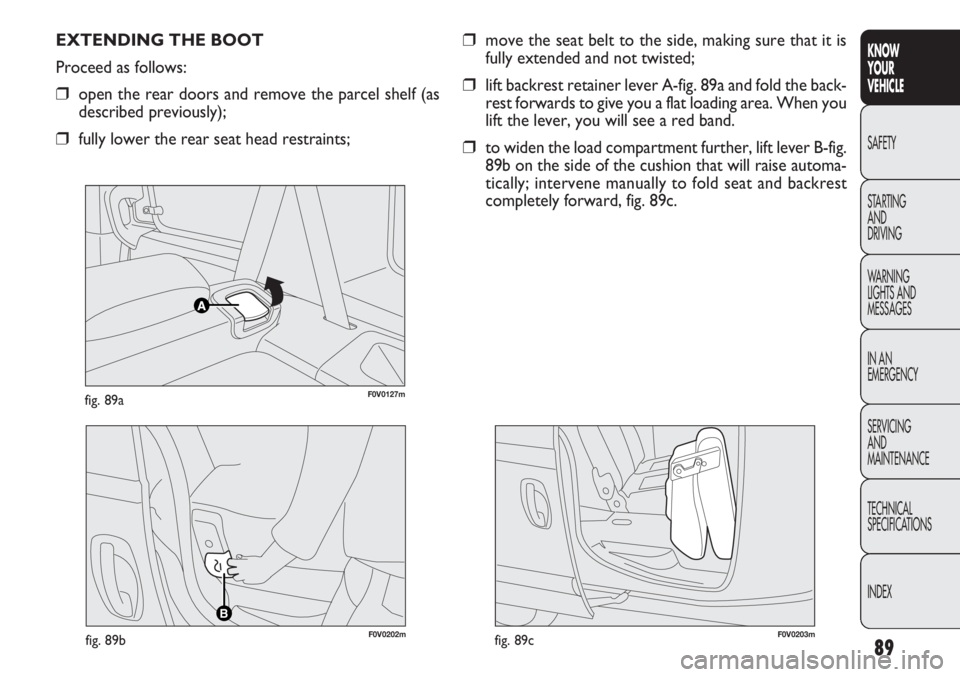
âť’lift backrest retainer lever A-fig. 89a and fold the back-
rest forwards to give you a flat loading area. When you
lift the lever, you will see a red band.
âť’to widen the load compartment further, lift lever B-fig.
89b on the side of the cushion that will raise automa-
tically; intervene manually to fold seat and backrest
completely forward, fig. 89c.
B
F0V0202mfig. 89bF0V0203mfig. 89c
Page 94 of 283
F0V0204mfig. 90
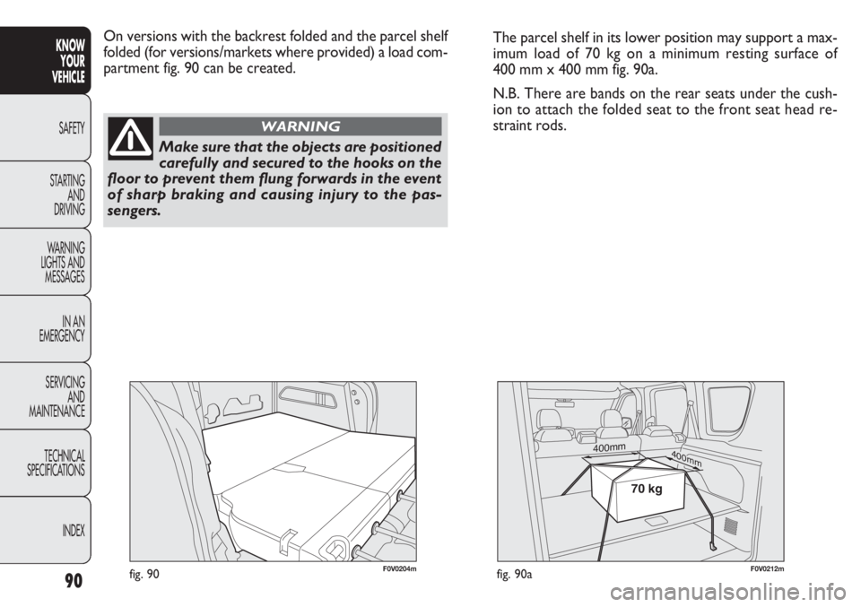
On versions with the backrest folded and the parcel shelf
folded (for versions/markets where provided) a load com-
partment fig. 90 can be created.
90
KNOWYOUR
VEHICLE
SAFETY
ST AR
TING AND
DRIVING
WARNING
LIGHTS AND MESSAGES
IN AN
EMERGENCY
SERVICING AND
MAINTENANCE
TECHNICAL
SPECIFICATIONS
INDEX
Make sure that the objects are positioned
carefully and secured to the hooks on the
floor to prevent them flung forwards in the event
of sharp braking and causing injury to the pas-
sengers.
WARNING
The parcel shelf in its lower position may support a max-
imum load of 70 kg on a minimum resting surface of
400 mm x 400 mm fig. 90a.
N.B. There are bands on the rear seats under the cush-
ion to attach the folded seat to the front seat head re-
straint rods.
400mm400mm
70 kg
F0V0212mfig. 90a
Page 95 of 283
91
KNOW
YOUR
VEHICLE
SAFETY
STAR
TING
AND
DRIVING
WARNING
LIGHTS AND
MESSAGES
IN AN
EMERGENCY
SERVICING
AND
MAINTENANCE
TECHNICAL
SPECIFICATIONS
INDEX
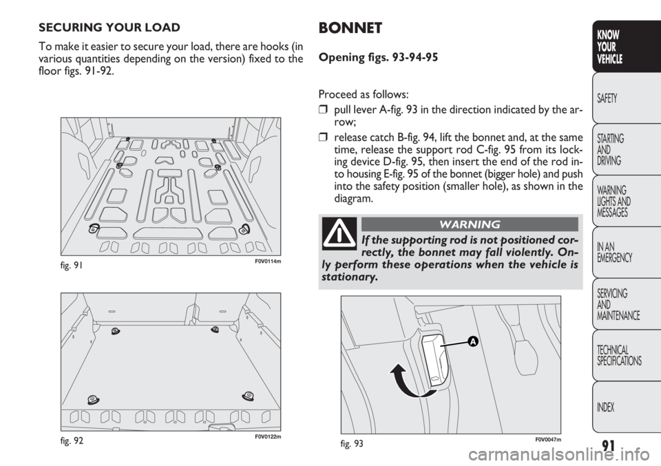
SECURING YOUR LOAD
To make it easier to secure your load, there are hooks (in
various quantities depending on the version) fixed to the
floor figs. 91-92.
F0V0047mfig. 93
BONNET
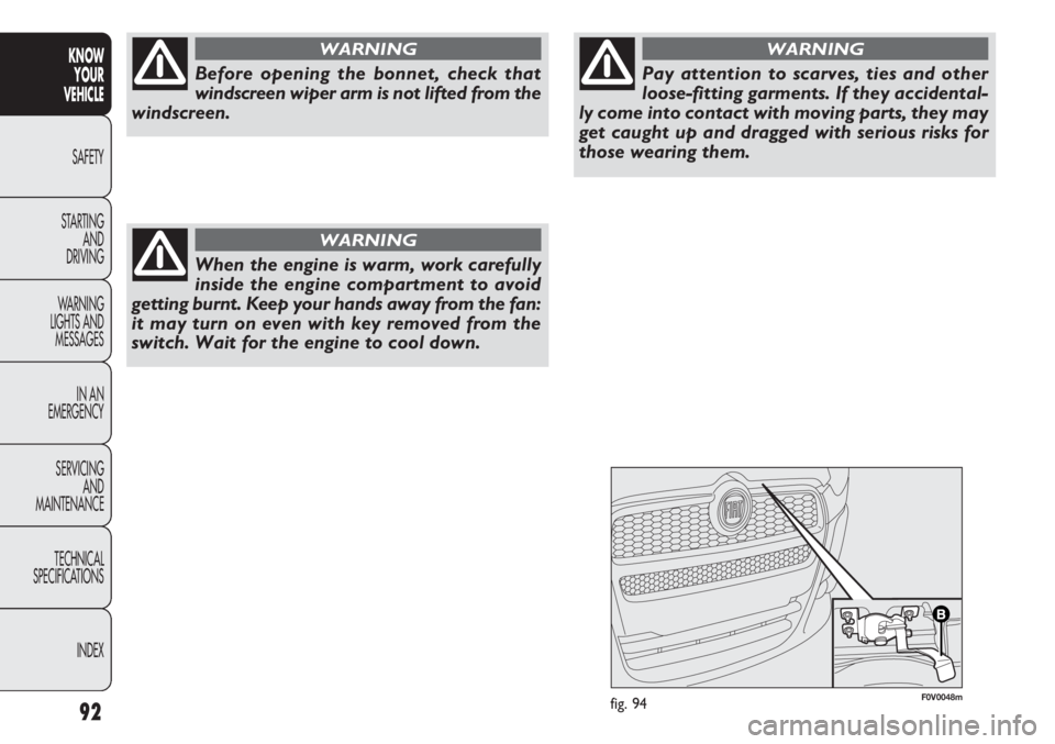
Opening figs. 93-94-95
Proceed as follows:
âť’pull lever A-fig. 93 in the direction indicated by the ar-
row;
âť’release catch B-fig. 94, lift the bonnet and, at the same
time, release the support rod C-fig. 95 from its lock-
ing device D-fig. 95, then insert the end of the rod in-
to housing E-fig. 95 of the bonnet (bigger hole) and push
into the safety position (smaller hole), as shown in the
diagram.
If the supporting rod is not positioned cor-
rectly, the bonnet may fall violently. On-
ly perform these operations when the vehicle is
stationary.
WARNING
F0V0122mfig. 92
F0V0114mfig. 91
Page 96 of 283
F0V0048mfig. 9492
KNOWYOUR
VEHICLE
SAFETY
ST AR
TING AND
DRIVING
WARNING
LIGHTS AND MESSAGES
IN AN
EMERGENCY
SERVICING AND
MAINTENANCE
TECHNICAL
SPECIFICATIONS
INDEX
Before opening the bonnet, check that
windscreen wiper arm is not lifted from the
windscreen.
WARNING
When the engine is warm, work carefully
inside the engine compartment to avoid
getting burnt. Keep your hands away from the fan:
it may turn on even with key removed from the
switch. Wait for the engine to cool down.
WARNING
Pay attention to scarves, ties and other
loose-fitting garments. If they accidental-
ly come into contact with moving parts, they may
get caught up and dragged with serious risks for
those wearing them.
WARNING
Page 97 of 283
93
KNOW
YOUR
VEHICLE
SAFETY
STAR
TING
AND
DRIVING
WARNING
LIGHTS AND
MESSAGES
IN AN
EMERGENCY
SERVICING
AND
MAINTENANCE
TECHNICAL
SPECIFICATIONS
INDEX
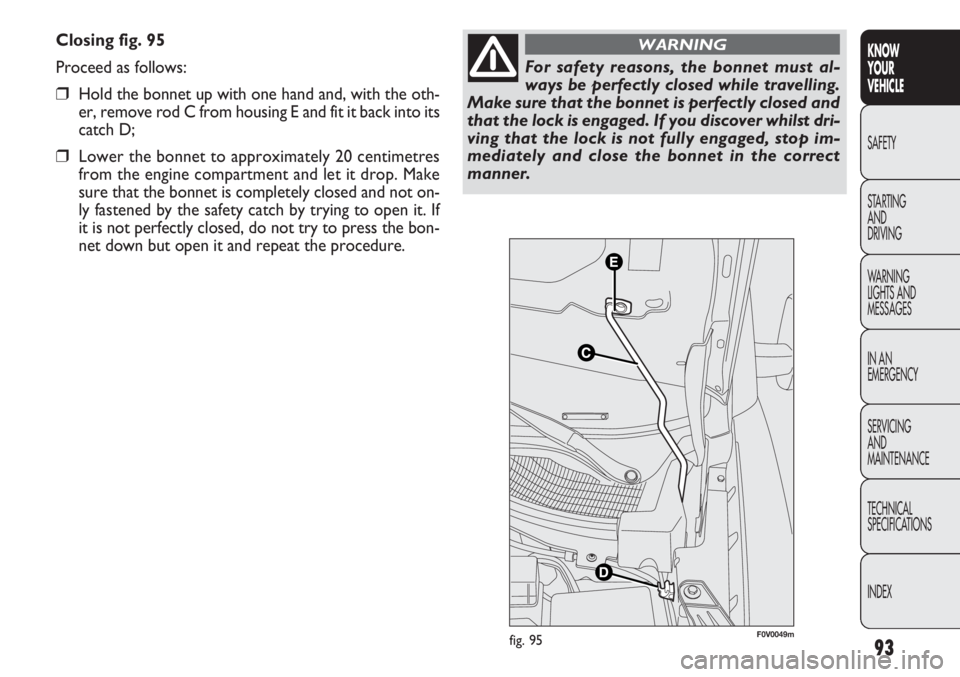
Closing fig. 95
Proceed as follows:
âť’Hold the bonnet up with one hand and, with the oth-
er, remove rod C from housing E and fit it back into its
catch D;
âť’Lower the bonnet to approximately 20 centimetres
from the engine compartment and let it drop. Make
sure that the bonnet is completely closed and not on-
ly fastened by the safety catch by trying to open it. If
it is not perfectly closed, do not try to press the bon-
net down but open it and repeat the procedure.
For safety reasons, the bonnet must al-
ways be perfectly closed while travelling.
Make sure that the bonnet is perfectly closed and
that the lock is engaged. If you discover whilst dri-
ving that the lock is not fully engaged, stop im-
mediately and close the bonnet in the correct
manner.
WARNING
F0V0049mfig. 95
Page 98 of 283
94
KNOWYOUR
VEHICLE
SAFETY
ST AR
TING AND
DRIVING
WARNING
LIGHTS AND MESSAGES
IN AN
EMERGENCY
SERVICING AND
MAINTENANCE
TECHNICAL
SPECIFICATIONS
INDEX
F0V0123mfig. 99
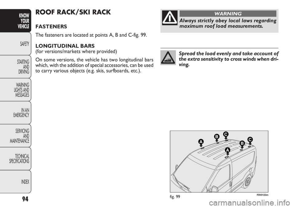
ROOF RACK/SKI RACK
FASTENERS
The fasteners are located at points A, B and C-fig. 99.
LONGITUDINAL BARS
(for versions/markets where provided)
On some versions, the vehicle has two longitudinal bars
which, with the addition of special accessories, can be used
to carry various objects (e.g. skis, surfboards, etc.).
Always strictly obey local laws regarding
maximum roof load measurements.
WARNING
Spread the load evenly and take account of
the extra sensitivity to cross winds when dri-
ving.
Page 99 of 283
95
KNOW
YOUR
VEHICLE
SAFETY
STAR
TING
AND
DRIVING
WARNING
LIGHTS AND
MESSAGES
IN AN
EMERGENCY
SERVICING
AND
MAINTENANCE
TECHNICAL
SPECIFICATIONS
INDEX
F0V0021mfig. 100
H EA DLIG HTS
LIGHT BEAM DIRECTION
The correct direction of the headlights is essential for the
comfort and safety of the driver and other road users.
To ensure the best visibility conditions when travelling with
the headlights on the headlight alignment must be correct.
Contact the Fiat Service Network to have the direction
checked and, if necessary, adjusted.
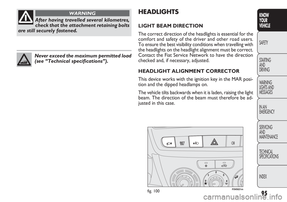
HEADLIGHT ALIGNMENT CORRECTOR
This device works with the ignition key in the MAR posi-
tion and the dipped headlamps on.
The vehicle tilts backwards when it is laden, raising the light
beam. The direction of the beam must therefore be ad-
justed in this case.
After having travelled several kilometres,
check that the attachment retaining bolts
are still securely fastened.
WARNING
Never exceed the maximum permitted load
(see “Technical specifications”).
Page 100 of 283
96
KNOWYOUR
VEHICLE
SAFETY
ST AR
TING AND
DRIVING
WARNING
LIGHTS AND MESSAGES
IN AN
EMERGENCY
SERVICING AND
MAINTENANCE
TECHNICAL
SPECIFICATIONS
INDEX
ABS SYSTEM
(for versions/markets where provided)
This is an integral part of the braking system, which pre-
vents one or more wheels from locking or slipping re-
gardless of the road surface conditions and braking action,
giving the best control during emergency braking.
The EBD system (Electronic Braking Force Distribution)
completes the system, allowing the braking action to be
distributed between the front and rear wheels.
WARNING For maximum efficiency of the braking sys-
tem, a bedding-in period of about 500 km is needed: dur-
ing this period it is better to avoid sharp, repeated and pro-
longed braking.
SYSTEM INTERVENTION
The driver can tell the ABS system has come into action
because the brake pedal pulsates slightly and the system
gets noisier: it means that the vehicle speed should be al-
tered to suit the type of road surface.
Headlamp alignment adjustment
To adjust, press buttons Òandfig. 100 on the control
panel.
The display located on the instrument panel provides the
visual indication of the positions during the adjustment op-
eration.
Position 0 – one or two people in the front seats.
Position 1 – five people.
Position 2 – five people + load in the boot.
Position 3 – driver + maximum permitted load stowed in the luggage compartment.
WARNING Check the light beam alignment every time
the load transported changes.
FOG LIGHT DIRECTION
(for versions/markets where provided)
Contact the Fiat Service Network to have the direction
checked and, if necessary, adjusted.
ADJUSTING THE HEADLIGHTS WHEN
ABROAD
The dipped headlamps are adjusted to work in the coun-
try where the vehicle was originally purchased. When in
countries where you drive on the other side of the road,
you need to alter the light beam direction by affixing a spe-
cially designed self-adhesive film in order not to dazzle the
vehicles travelling in the opposite direction. This film is
provided by Lineaccessori Fiat and is available at Fiat Ser-
vice Network.
When the ABS intervenes and you notice
the brake pedal pulsating, do not be afraid
to keep the pedal pushed down. This will help you
to stop in the shortest distance possible, depend-
ing on the road conditions.
WARNING