FIAT DOBLO COMBI 2013 Owner handbook (in English)
Manufacturer: FIAT, Model Year: 2013, Model line: DOBLO COMBI, Model: FIAT DOBLO COMBI 2013Pages: 283, PDF Size: 6.31 MB
Page 111 of 283
107
KNOW
YOUR
VEHICLE
SAFETY
STAR
TING
AND
DRIVING
WARNING
LIGHTS AND
MESSAGES
IN AN
EMERGENCY
SERVICING
AND
MAINTENANCE
TECHNICAL
SPECIFICATIONS
INDEX
F0V0041mfig. 105
ENERGY SAVING FUNCTION
(for versions/markets where provided)
If, after the engine has been automatically restarted, the
driver does not take any action for a period of about 3 min-
utes, the Start&Stop system will definitively stop the en-
gine to avoid fuel consumption. The engine can only be
started using the key in such cases.
N.B.: In any case, it is possible to keep the engine running
by deactivating the Start&Stop system.
OPERATING IRREGULARITIES
In the case of malfunctions the Start&Stop system is dis-
abled. The driver is informed of the problem by the gen-
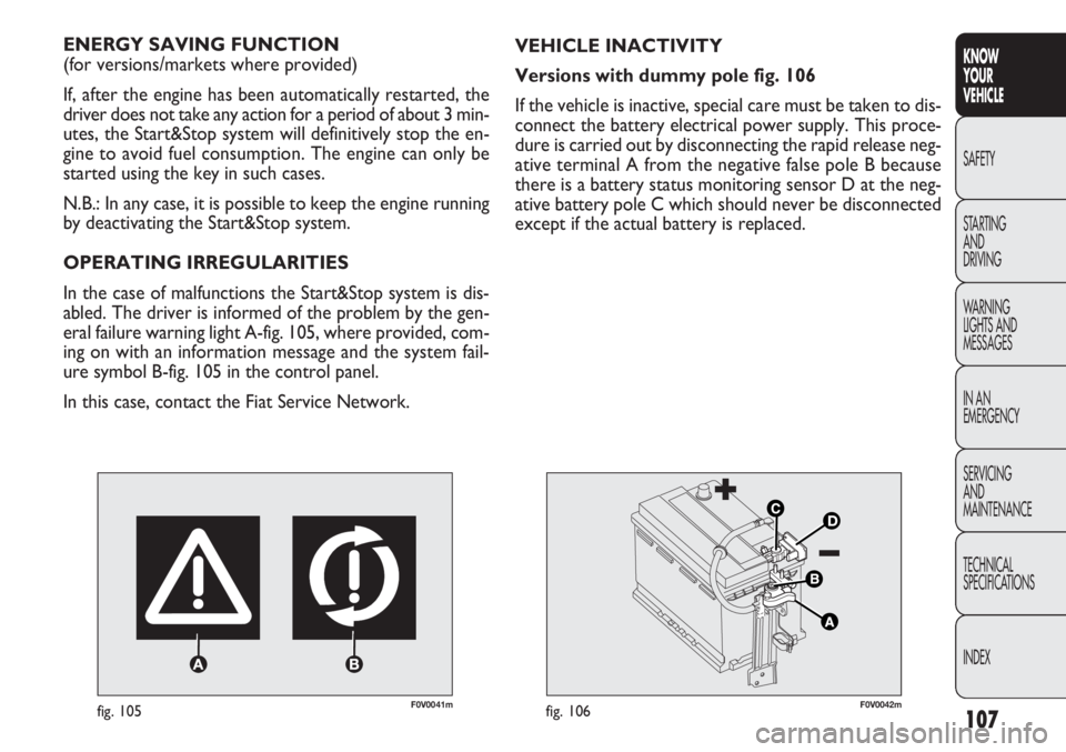
eral failure warning light A-fig. 105, where provided, com-
ing on with an information message and the system fail-
ure symbol B-fig. 105 in the control panel.
In this case, contact the Fiat Service Network. VEHICLE INACTIVITY
Versions with dummy pole fig. 106
If the vehicle is inactive, special care must be taken to dis-
connect the battery electrical power supply. This proce-
dure is carried out by disconnecting the rapid release neg-
ative terminal A from the negative false pole B because
there is a battery status monitoring sensor D at the neg-
ative battery pole C which should never be disconnected
except if the actual battery is replaced.
F0V0042mfig. 106
Page 112 of 283
108
KNOWYOUR
VEHICLE
SAFETY
ST AR
TING AND
DRIVING
WARNING
LIGHTS AND MESSAGES
IN AN
EMERGENCY
SERVICING AND
MAINTENANCE
TECHNICAL
SPECIFICATIONS
INDEX
F0V0043mfig. 107
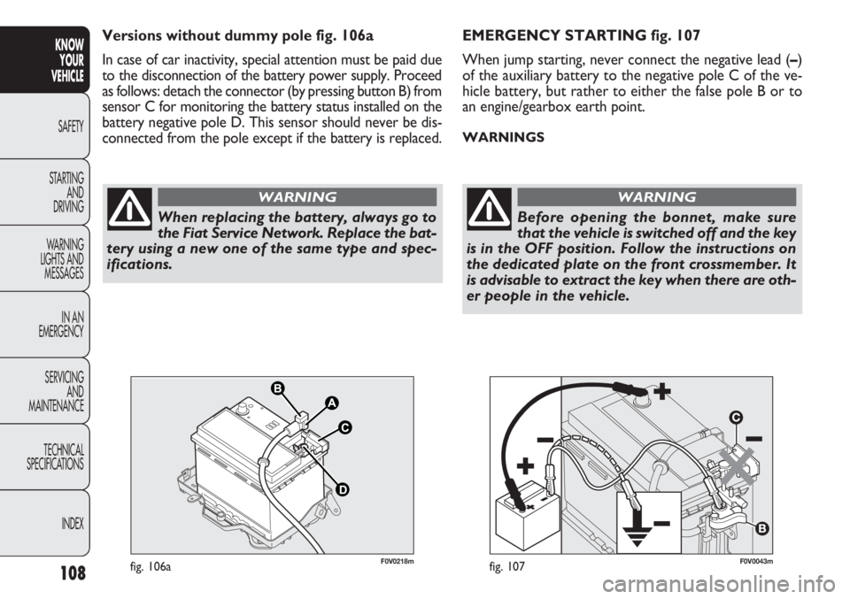
EMERGENCY STARTING fig. 107
When jump starting, never connect the negative lead ( –)
of the auxiliary battery to the negative pole C of the ve-
hicle battery, but rather to either the false pole B or to
an engine/gearbox earth point.
WARNINGS
When replacing the battery, always go to
the Fiat Service Network. Replace the bat-
tery using a new one of the same type and spec-
ifications.
WARNING
Before opening the bonnet, make sure
that the vehicle is switched off and the key
is in the OFF position. Follow the instructions on
the dedicated plate on the front crossmember. It
is advisable to extract the key when there are oth-
er people in the vehicle.
WARNING
F0V0218mfig. 106a
Versions without dummy pole fig. 106a
In case of car inactivity, special attention must be paid due
to the disconnection of the battery power supply. Proceed
as follows: detach the connector (by pressing button B) from
sensor C for monitoring the battery status installed on the
battery negative pole D. This sensor should never be dis-
connected from the pole except if the battery is replaced.
Page 113 of 283
109
KNOW
YOUR
VEHICLE
SAFETY
STAR
TING
AND
DRIVING
WARNING
LIGHTS AND
MESSAGES
IN AN
EMERGENCY
SERVICING
AND
MAINTENANCE
TECHNICAL
SPECIFICATIONS
INDEX
RADIO
(for versions/markets where provided)
For the operation of the radio with CD/MP3 player (for
versions/markets where provided), read the Supplement
attached to this Owner’s Handbook.
WIRING FOR LIGHTWEIGHT SYSTEM
The system consists of:
❒radio power cables;
❒front speaker cables (located on door mirror trims);
❒speaker cables on front door panels;
❒rear speaker cables (located next to the parcel shelf)
(for versions/markets where provided);
❒radio compartment;
❒aerial lead;
❒aerial.
WIRING FOR HEAVYWEIGHT SYSTEM
The system consists of:
❒radio power cables;
❒rear speaker cables (located next to the parcel shelf)
(for versions/markets where provided);
❒two tweeters on the door mirror trims;
❒two midwoofers on the lower part of the front doors;
The vehicle should always be evacuated
after the key has been removed or turned
to the OFF position. During refuelling operations,
it is necessary to make sure that the vehicle is off
with the ignition key in the OFF position.
WARNING
For vehicles with a robotised transmission,
if the engine cuts out automatically on
a gradient, it is advisable to restart the engine by
moving the gear lever towards (+) or (-) without
releasing the brake pedal. For vehicles with ro-
botised transmission, where the Hill Holder func-
tion is present, if the engine cuts out automati-
cally whilst on a hill, it is advisable to restart it
by moving the gear lever to (+) or (-) without re-
leasing the brake pedal to make the Hill Holder
function – which is only active when the engine
is running – available.
WARNING
If you want to prioritise climate comfort,
the Start&Stop system can be disabled to
allow continuous operation of the climate control
system.
WARNING
Page 114 of 283
110
KNOWYOUR
VEHICLE
SAFETY
ST AR
TING AND
DRIVING
WARNING
LIGHTS AND MESSAGES
IN AN
EMERGENCY
SERVICING AND
MAINTENANCE
TECHNICAL
SPECIFICATIONS
INDEX
F0V0068mfig. 108
INSTALLING ELECTRICAL/
ELECTRONIC DEVICES
Electrical and electronic devices installed after buying the
vehicle by aftersales must carry the following label:
FGA S.p.A. authorises the installation of transceiving de-
vices provided that they are installed by a specialised cen-
tre according to rules of good engineering practice and
in compliance with the manufacturer’s instructions.
WARNING Traffic authorities may not allow the vehicle
on the road if devices are fitted that modify vehicle spec-
ifications. This may also invalidate the warranty in rela-
tion to faults caused by the change or either directly or in-
directly related to it.
FGA S.p.A. shall not be liable for damage caused by the in-
stallation of accessories either not supplied or recom-
mended by FGA S.p.A. and/or not installed in compliance
with the provided instructions.
RADIO TRANSMITTERS
AND MOBILE PHONES
Radiotransmitting apparatus (e.g. car mobile phones, CB
radios etc.) should not be used inside the vehicle unless
a separate aerial is mounted on the roof.
❒two rear speakers (located next to the parcel shelf)
(for versions/markets where provided);
❒radio compartment;
❒aerial lead;
❒aerial.
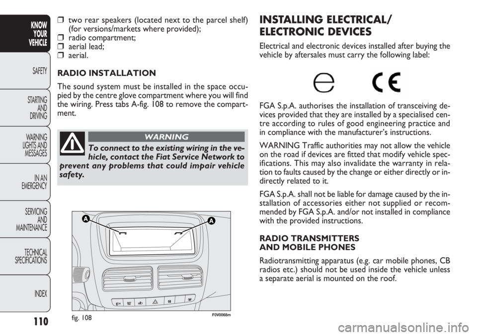
RADIO INSTALLATION
The sound system must be installed in the space occu-
pied by the centre glove compartment where you will find
the wiring. Press tabs A-fig. 108 to remove the compart-
ment.
To connect to the existing wiring in the ve-
hicle, contact the Fiat Service Network to
prevent any problems that could impair vehicle
safety.
WARNING
Page 115 of 283
111
KNOW
YOUR
VEHICLE
SAFETY
STAR
TING
AND
DRIVING
WARNING
LIGHTS AND
MESSAGES
IN AN
EMERGENCY
SERVICING
AND
MAINTENANCE
TECHNICAL
SPECIFICATIONS
INDEX
REFUELLING THE VEHICLE
PETROL ENGINES
Use unleaded petrol only, with an octane number (R.O.N.)
no lower than 95.
WARNING An inefficient catalytic silencer leads to harm-
ful exhaust emissions, thus contributing to air pollution.
WARNING Never use leaded petrol, even in small
amounts or in an emergency, as this would damage the
catalytic silencer beyond repair.
DIESEL ENGINES
Operation at low temperatures
If the outside temperature is very low, the diesel thick-
ens due to the formation of paraffin clots with consequent
defective operation of the fuel supply system.
In order to avoid these problems, different types of diesel
are distributed according to the season: summer type, win-
ter type and arctic type (cold/mountain areas). If refuelling
with diesel fuel whose specifications are not suitable for
the usage temperature, it is advisable to mix TUTELA
DIESEL ART additive in the proportions shown on the con-
tainer with the fuel. Pour the additive into the tank before
the fuel.
WARNING The use of similar devices inside the passen-
ger compartment (without an external aerial) may, in ad-
dition to potential damage to the health of the passengers,
cause malfunctions in the vehicle electronic systems, com-
promising the safety of the vehicle.
In addition, the transmission and reception of these de-
vices may be affected by the shielding effect of the vehi-
cle body.
With regard to EC-approved mobile phones (GSM, GPRS,
UMTS), you should adhere strictly to the instructions pro-
vided by the mobile phone’s manufacturer.
Page 116 of 283
112
KNOWYOUR
VEHICLE
SAFETY
ST AR
TING AND
DRIVING
WARNING
LIGHTS AND MESSAGES
IN AN
EMERGENCY
SERVICING AND
MAINTENANCE
TECHNICAL
SPECIFICATIONS
INDEX
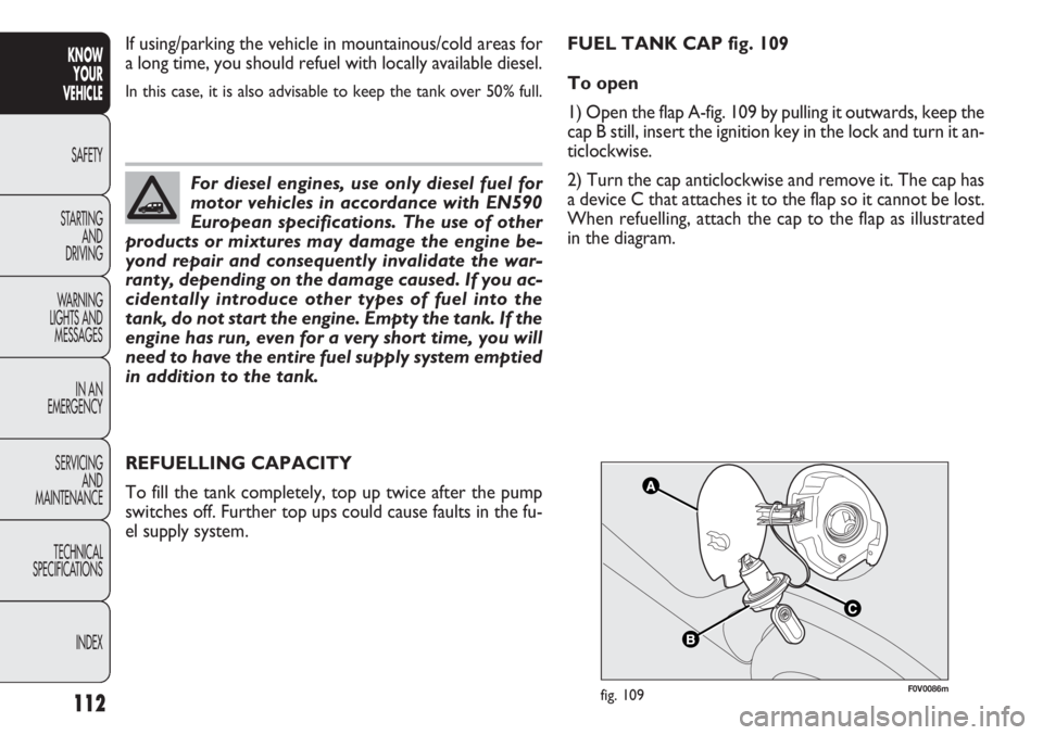
F0V0086mfig. 109
REFUELLING CAPACITY
To fill the tank completely, top up twice after the pump
switches off. Further top ups could cause faults in the fu-
el supply system. If using/parking the vehicle in mountainous/cold areas for
a long time, you should refuel with locally available diesel.
In this case, it is also advisable to keep the tank over 50% full.
For diesel engines, use only diesel fuel for
motor vehicles in accordance with EN590
European specifications. The use of other
products or mixtures may damage the engine be-
yond repair and consequently invalidate the war-
ranty, depending on the damage caused. If you ac-
cidentally introduce other types of fuel into the
tank, do not start the engine. Empty the tank. If the
engine has run, even for a very short time, you will
need to have the entire fuel supply system emptied
in addition to the tank.
FUEL TANK CAP fig. 109
To open
1) Open the flap A-fig. 109 by pulling it outwards, keep the
cap B still, insert the ignition key in the lock and turn it an-
ticlockwise.
2) Turn the cap anticlockwise and remove it. The cap has
a device C that attaches it to the flap so it cannot be lost.
When refuelling, attach the cap to the flap as illustrated
in the diagram.
Page 117 of 283
113
KNOW
YOUR
VEHICLE
SAFETY
STAR
TING
AND
DRIVING
WARNING
LIGHTS AND
MESSAGES
IN AN
EMERGENCY
SERVICING
AND
MAINTENANCE
TECHNICAL
SPECIFICATIONS
INDEX
PROTECTING THE ENVIRONMENT
The devices for reducing petrol engine emissions are the
following:
❒three-way catalytic converter;
❒Lambda sensors;
❒evaporation prevention system.
In addition, do not let the engine run, even for a test, with
one or more spark plugs disconnected.
The following devices are used for reducing diesel fuel en-
gine emissions:
❒oxidising catalytic converter;
❒exhaust gas recirculation system (EGR);
❒diesel particulate filter (DPF) (for versions/markets
where provided).
To close
1) Fit the cap (complete with key) and turn it clockwise
until it clicks once or more.
2) Turn the key clockwise and extract it, then close the
flap.
The hermetic seal may cause a slight increase in pressure
in the tank. A suction noise when you release the cap is
therefore entirely normal.
Do not place naked flames or lit cigarettes
near to the fuel tank opening: fire risk. Keep
your face away from the fuel tank open-
ing to avoid breathing in harmful vapours.
Page 118 of 283
114
KNOWYOUR
VEHICLE
SAFETY
ST AR
TING AND
DRIVING
WARNING
LIGHTS AND MESSAGES
IN AN
EMERGENCY
SERVICING AND
MAINTENANCE
TECHNICAL
SPECIFICATIONS
INDEX
DIESEL PARTICULATE FILTER (DPF)
(for versions/markets where provided)
The Diesel Particulate Filter is a mechanical filter, inte-
gral with the exhaust system, that physically traps carbon
particles present in the exhaust gases of Diesel engines.
It is needed to eliminate almost all carbon particles in com-
pliance with current/future legislation. During normal use
of the vehicle, the engine management control unit records
a set of data (e.g. journey time, type of route, tempera-
tures, etc.) and it will then calculate how much particu-
late has been trapped by the filter. Since the filter is a collecting system, it should be regular-
ly regenerated (cleaned) by burning the carbon particles.
The regeneration procedure is controlled automatically by
the engine management control unit according to the fil-
ter conditions and vehicle use conditions.
During regeneration, the following may occur: a limited in-
crease in the engine speed, activation of the fan, a limited
increase in fumes and high temperatures at the exhaust.
These are not faults; they do not impair vehicle perfor-
mance or damage the environment. If the dedicated mes-
sage is displayed, refer to the “Warning lights and mes-
sages” section.
Page 119 of 283
115
KNOW
YOUR
VEHICLE
SAFETY
STARTING
AND
DRIVING
WARNING
LIGHTS AND
MESSAGES
IN AN
EMERGENCY
SERVICING
AND
MAINTENANCE
TECHNICAL
SPECIFICA
TIONS
INDEX
F0V0023mfig. 110
Through the reel, the belt automatically adapts to the body
of the passenger wearing it, allowing freedom of move-
ment.
The reel may lock up when the vehicle is parked on a steep
slope: this is perfectly normal. Furthermore, the reel mech-
anism locks the belt if it is pulled sharply or in the event
of sudden braking, collisions and high-speed bends.SEAT BELT S
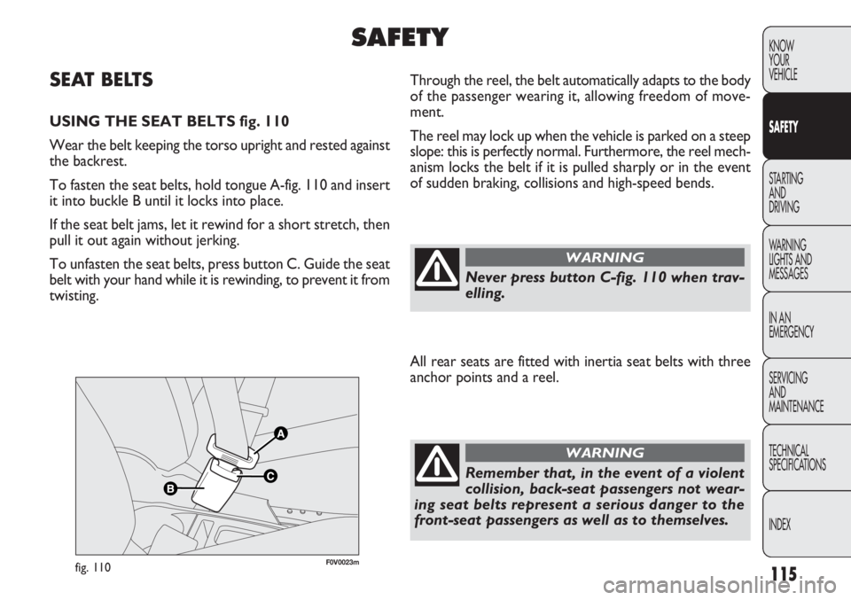
USING THE SEAT BELTS fig. 110
Wear the belt keeping the torso upright and rested against
the backrest.
To fasten the seat belts, hold tongue A-fig. 110 and insert
it into buckle B until it locks into place.
If the seat belt jams, let it rewind for a short stretch, then
pull it out again without jerking.
To unfasten the seat belts, press button C. Guide the seat
belt with your hand while it is rewinding, to prevent it from
twisting.
SAFETY
Never press button C-fig. 110 when trav-
elling.
WARNING
All rear seats are fitted with inertia seat belts with three
anchor points and a reel.
Remember that, in the event of a violent
collision, back-seat passengers not wear-
ing seat belts represent a serious danger to the
front-seat passengers as well as to themselves.
WARNING
Page 120 of 283
116
KNOWYOUR
VEHICLE
SAFETY
STARTING AND
DRIVING
W ARNING
LIGHTS AND MESSAGES
IN AN
EMERGENCY
SERVICING AND
MAINTENANCE
TECHNICAL
SPECIFICA
TIONSINDEX
F0V0126mfig. 111a - Rear seats 1strow
F0V0127mfig. 112
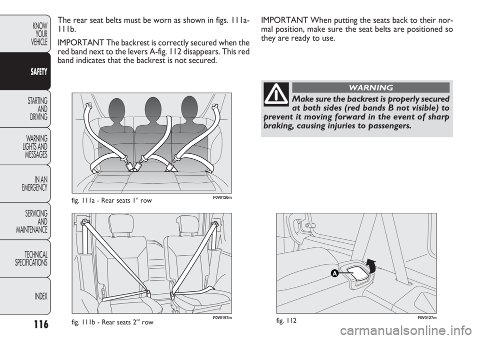
The rear seat belts must be worn as shown in figs. 111a-
111b.
IMPORTANT The backrest is correctly secured when the
red band next to the levers A-fig. 112 disappears. This red
band indicates that the backrest is not secured.
Make sure the backrest is properly secured
at both sides (red bands B not visible) to
prevent it moving forward in the event of sharp
braking, causing injuries to passengers.
WARNING
IMPORTANT When putting the seats back to their nor-
mal position, make sure the seat belts are positioned so
they are ready to use.
F0V0197mfig. 111b - Rear seats 2ndrow