mirror FIAT DOBLO COMBI 2018 Owner handbook (in English)
[x] Cancel search | Manufacturer: FIAT, Model Year: 2018, Model line: DOBLO COMBI, Model: FIAT DOBLO COMBI 2018Pages: 272, PDF Size: 23.75 MB
Page 6 of 272
USE OF THE OWNER HANDBOOK
OPERATING INSTRUCTIONS
Each time direction instructions (left/right or forwards/backwards) about the vehicle are given, these must be intended as
regarding an occupant in the driver's seat. Special cases not complying with this rule will be specified as appropriate in the text.
The figures in the Owner Handbook are provided by way of example only: this might imply that some details of the image do
not correspond to the actual arrangement of your vehicle. In addition, the Handbook has been conceived considering vehicles
with steering wheel on the left side; it is therefore possible that on vehicles with steering wheel on the right side, the position
or construction of some controls is not exactly mirror-like with respect to the figure.
To identify the chapter with the information needed you can consult the index at the end of this Owner Handbook.
Chapters can be rapidly identified with dedicated graphic tabs, at the side of each odd page. A few pages further there is a key
for getting to know the chapter order and the relevant symbols in the tabs. There is in any case a textual indication of the
current chapter at the side of each even page.
WARNINGS AND PRECAUTIONS
While reading this Owner Handbook you will find a series ofWARNINGSto prevent procedures that could damage your
vehicle.
There are alsoPRECAUTIONSthat must be carefully followed to prevent incorrect use of the components of the vehicle,
which could cause accidents or injuries.
Therefore allWARNINGSandPRECAUTIONSmust always be carefully followed.
WARNINGSandPRECAUTIONSare recalled in the text with the following symbols:
personal safety;
vehicle integrity;
environmental protection.
NOTE These symbols, when necessary, are indicated besides the title or at the end of the line and are followed by a number.
That number recalls the corresponding warning at the end of the relevant section.
Page 11 of 272
KNOWING YOUR VEHICLE
In-depth knowledge of your new vehicle
starts here.
The booklet that you are reading simply
and directly explains how it is made
and how it works.
That’s why we advise you to read it
seated comfortably on board, so that
you can see what is described here for
yourself.KEYS .............................................. 10
IGNITION DEVICE ........................... 11
THE FIAT CODE SYSTEM ............... 12
DOORS ........................................... 13
SEATS ............................................ 17
PARTITIONS ................................... 23
HEADRESTS ................................... 25
STEERING WHEEL ......................... 26
REAR VIEW MIRRORS .................... 27
EXTERIOR LIGHTS ......................... 28
INTERIOR LIGHTS .......................... 30
WINDSCREEN / REAR WINDOW
WIPERS .......................................... 32
HEATING AND VENTILATION.......... 34
MANUAL CLIMATE CONTROL
SYSTEM ......................................... 36
AUTOMATIC CLIMATE CONTROL
SYSTEM ......................................... 38
ELECTRIC WINDOWS .................... 40
BONNET ......................................... 41
LUGGAGE COMPARTMENT ........... 42
HEADLIGHTS.................................. 46
VERSION WITH METHANE
SYSTEM (NATURAL POWER) ......... 47
9
Page 29 of 272
REAR VIEW
MIRRORS
INTERIOR MIRROR
(for versions/markets, where provided)
The mirror is fitted with a safety device
that causes its release in the event of
a violent impact with the passenger.
Lever A fig. 51 can be used to move
the mirror to two different positions:
normal or antiglare.
Some versions may feature an internal
child surveillance mirror B fig. 52.
DOOR MIRRORS
Manual mirror folding
When required (for example when the
shape causes difficulty in narrow
spaces), the mirrors can be folded by
moving them from position A fig. 53
to position B.
26)
Manual adjustment
From inside, use device A fig. 54.
Electric adjustment
(for versions/markets, where provided)
Door mirrors can be adjusted only if the
ignition key is in MAR position.
Proceed as follows:
select the required mirror with switch
A fig. 55 (right or left);
move switch A to position B and
manipulate it to adjust the left door
mirror;
turn switch A to position D and
manipulate it to adjust the right door
mirror.
Once you have finished the adjustment,
return switch A to intermediate locking
position C.
Electric folding
Door mirrors can be folded only if the
ignition key is in MAR position.
Bring switch A fig. 55 to position E to
fold the mirrors in the closed position.
Bring switch A to position C to move
the mirrors back to the driving position.
51F0V0125
52F0V0542
53F0V0084
54F0V0120
27
Page 30 of 272
WARNING
26)When driving, the mirrors shall always
be in position A fig. 53. As door mirrors are
curved, they may slightly alter the
perception of distance.
EXTERIOR LIGHTS
IN BRIEF
The left stalk includes the controls for
the exterior lights.
The external lights can only be
switched on when the ignition key is
at MAR.
The instrument panel and the various
dashboard controls will come on
with the external lights.
DAYTIME RUNNING
LIGHTS (DRL)
(for versions/markets, where provided)
With the key in MAR position and
the ring nut turned toOposition, the
daytime lights switch on automatically;
the other lights and the internal lighting
remain off. In some markets, the
automatic operation of the daytime
running lights can be activated/
deactivated via the display menu (see
"Digital/multifunction display" in this
section). If the daytime running lights
are deactivated, no light comes on
when the ring nut is turned toO.When the daytime running lights are on,
activating the direction indicators will
turn off the corresponding headlight’s
daytime running light (D.R.L.).27)
DIPPED HEADLIGHTS/
SIDE LIGHTS
With the ignition key turned to MAR,
turn the ring nut to
. If dipped
headlights are activated, the daytime
running lights switch off and the side
lights and dipped headlights switch on.
The
warning light switches on in
the instrument panel. When the ignition
key is turned to STOP or removed
and the ring nut is turned fromOto
, all the side lights and the number
plate lights come on. The
warning
light will come on in the instrument
panel.
55F0V0560
56F0V0515
28
KNOWING YOUR VEHICLE
Page 37 of 272
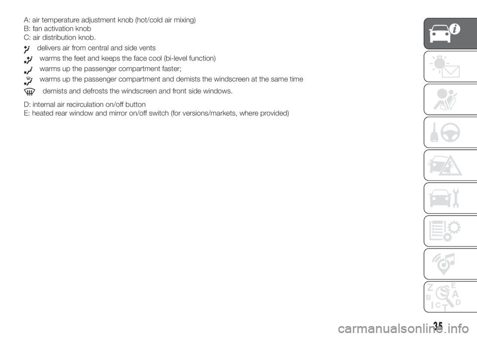
A: air temperature adjustment knob (hot/cold air mixing)
B: fan activation knob
C: air distribution knob.
delivers air from central and side vents
warms the feet and keeps the face cool (bi-level function)
warms up the passenger compartment faster;
warms up the passenger compartment and demists the windscreen at the same time
demists and defrosts the windscreen and front side windows.
D: internal air recirculation on/off button
E: heated rear window and mirror on/off switch (for versions/markets, where provided)
35
Page 39 of 272
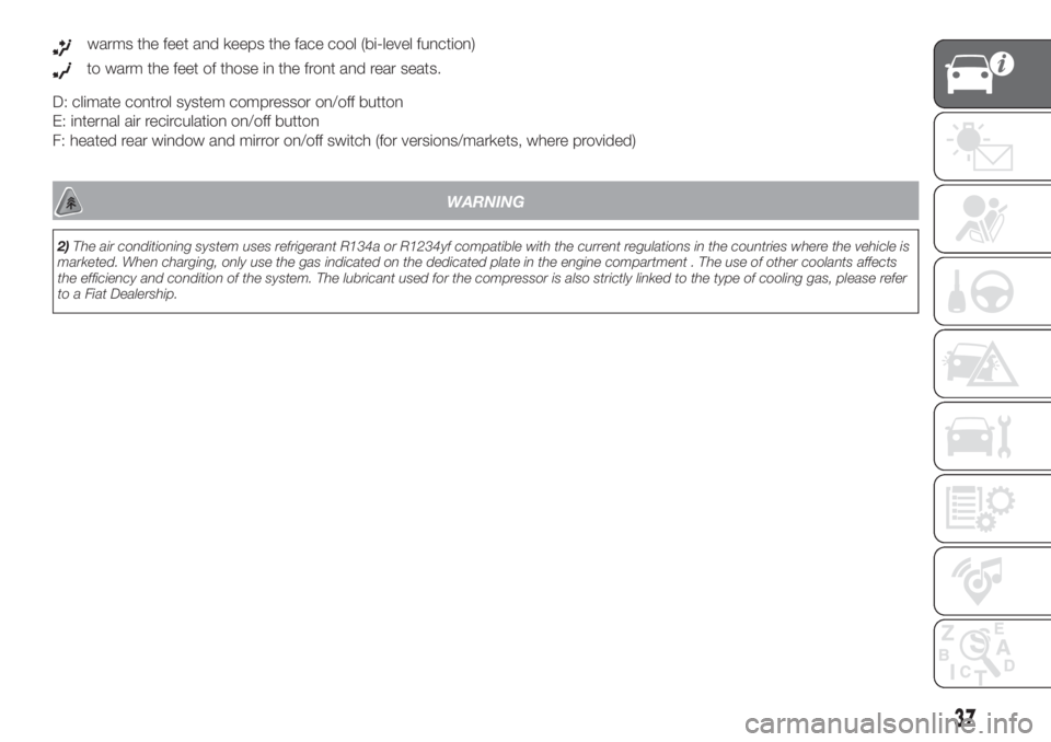
warms the feet and keeps the face cool (bi-level function)
to warm the feet of those in the front and rear seats.
D: climate control system compressor on/off button
E: internal air recirculation on/off button
F: heated rear window and mirror on/off switch (for versions/markets, where provided)
.
WARNING
2)The air conditioning system uses refrigerant R134a or R1234yf compatible with the current regulations in the countries where the vehicle is
marketed. When charging, only use the gas indicated on the dedicated plate in the engine compartment . The use of other coolants affects
the efficiency and condition of the system. The lubricant used for the compressor is also strictly linked to the type of cooling gas, please refer
to a Fiat Dealership.
37
Page 41 of 272

Air flow distributed between footwell diffusers (hotter air) and central and side dashboard vents (cooler air). This
distribution mode is particularly useful in spring and autumn on sunny days.
Air flow distributed between the footwell vents and the windscreen and front side window defrosting/demisting vents.
This allows an adequate warming of the passenger compartment and prevents the windows from misting up.
C Display.
D MAX DEF function control button.
E System deactivation button.
F Compressor on/off control button.
G Air recirculation control button.
H Fan speed increase/decrease control buttons.
I Temperature increase/decrease control knob.
L Heated rear window and electric door mirror on/off button (for versions/markets, where provided).
39
Page 85 of 272
SBR SYSTEM
This system comprises an acoustic
warning which, in conjunction with the
warning lights
flashing on the
instrument panel, warns the front seat
passengers if their seat belt has not
been fastened.
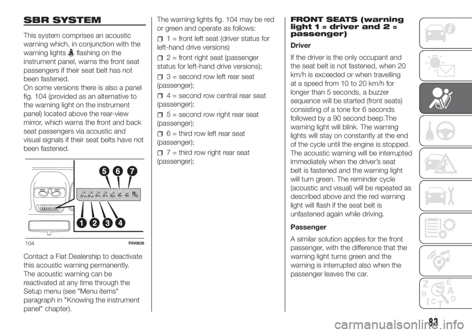
On some versions there is also a panel
fig. 104 (provided as an alternative to
the warning light on the instrument
panel) located above the rear-view
mirror, which warns the front and back
seat passengers via acoustic and
visual signals if their seat belts have not
been fastened.
Contact a Fiat Dealership to deactivate
this acoustic warning permanently.
The acoustic warning can be
reactivated at any time through the
Setup menu (see "Menu items"
paragraph in "Knowing the instrument
panel" chapter).The warning lights fig. 104 may be red
or green and operate as follows:
1 = front left seat (driver status for
left-hand drive versions)
2 = front right seat (passenger
status for left-hand drive versions);
3 = second row left rear seat
(passenger);
4 = second row central rear seat
(passenger);
5 = second row right rear seat
(passenger);
6 = third row left rear seat
(passenger);
7 = third row right rear seat
(passenger);FRONT SEATS (warning
light 1 = driver and 2 =
passenger)
Driver
If the driver is the only occupant and
the seat belt is not fastened, when 20
km/h is exceeded or when travelling
at a speed from 10 to 20 km/h for
longer than 5 seconds, a buzzer
sequence will be started (front seats)
consisting of a tone for 6 seconds
followed by a 90 second beep.The
warning light will blink. The warning
lights will stay on constantly at the end
of the cycle until the engine is stopped.
The acoustic warning will be interrupted
immediately when the driver’s seat
belt is fastened and the warning light
will turn green. The reminder cycle
(acoustic and visual) will be repeated as
described above and the red warning
light will flash if the seat belt is
unfastened again while driving.
Passenger
A similar solution applies for the front
passenger, with the difference that the
warning light turns green and the
warning is interrupted also when the
passenger leaves the car.
104F0V0635
83
Page 121 of 272
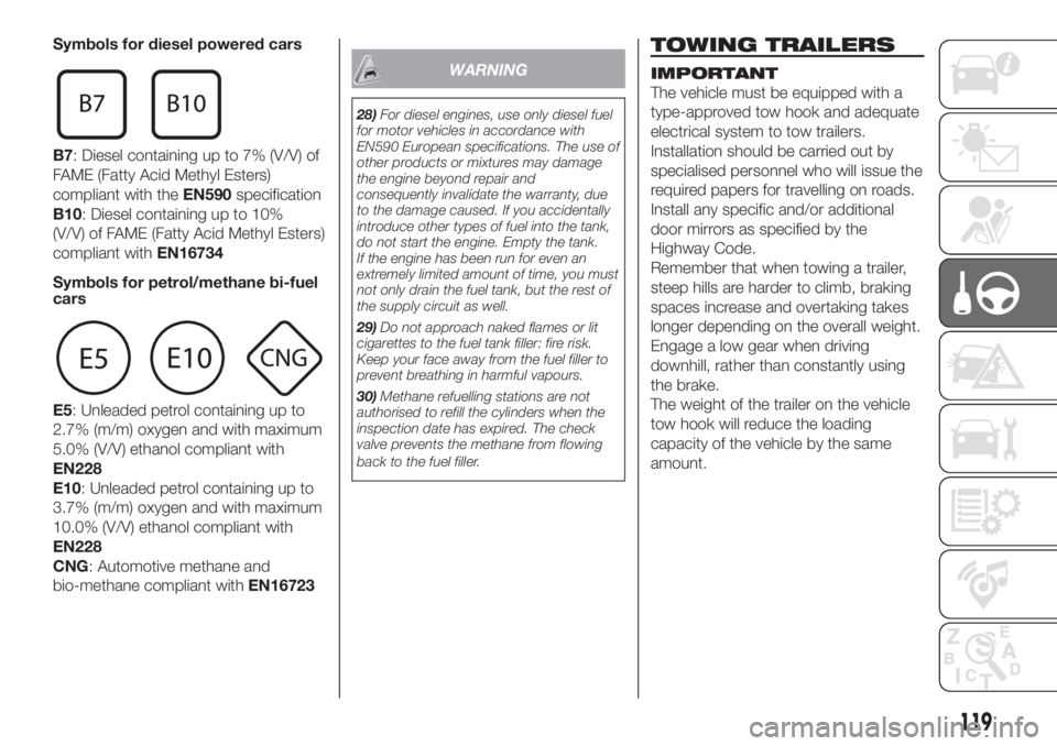
Symbols for diesel powered cars
B7: Diesel containing up to 7% (V/V) of
FAME (Fatty Acid Methyl Esters)
compliant with theEN590specification
B10: Diesel containing up to 10%
(V/V) of FAME (Fatty Acid Methyl Esters)
compliant withEN16734
Symbols for petrol/methane bi-fuel
cars
E5: Unleaded petrol containing up to
2.7% (m/m) oxygen and with maximum
5.0% (V/V) ethanol compliant with
EN228
E10: Unleaded petrol containing up to
3.7% (m/m) oxygen and with maximum
10.0% (V/V) ethanol compliant with
EN228
CNG: Automotive methane and
bio-methane compliant withEN16723
WARNING
28)For diesel engines, use only diesel fuel
for motor vehicles in accordance with
EN590 European specifications. The use of
other products or mixtures may damage
the engine beyond repair and
consequently invalidate the warranty, due
to the damage caused. If you accidentally
introduce other types of fuel into the tank,
do not start the engine. Empty the tank.
If the engine has been run for even an
extremely limited amount of time, you must
not only drain the fuel tank, but the rest of
the supply circuit as well.
29)Do not approach naked flames or lit
cigarettes to the fuel tank filler: fire risk.
Keep your face away from the fuel filler to
prevent breathing in harmful vapours.
30)Methane refuelling stations are not
authorised to refill the cylinders when the
inspection date has expired. The check
valve prevents the methane from flowing
back to the fuel filler.
TOWING TRAILERS
IMPORTANT
The vehicle must be equipped with a
type-approved tow hook and adequate
electrical system to tow trailers.
Installation should be carried out by
specialised personnel who will issue the
required papers for travelling on roads.
Install any specific and/or additional
door mirrors as specified by the
Highway Code.
Remember that when towing a trailer,
steep hills are harder to climb, braking
spaces increase and overtaking takes
longer depending on the overall weight.
Engage a low gear when driving
downhill, rather than constantly using
the brake.
The weight of the trailer on the vehicle
tow hook will reduce the loading
capacity of the vehicle by the same
amount.
119
Page 128 of 272
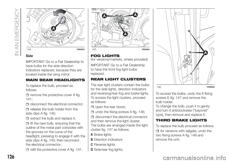
Side
IMPORTANT Go to a Fiat Dealership to
have bulbs for the side direction
indicators replaced, because they are
located inside the wing mirror.
MAIN BEAM HEADLIGHTS
To replace the bulb, proceed as
follows:
remove the protective cover A fig.
141;
disconnect the electrical connector;
release the bulb holder from the
side clips A fig. 145;
extract the bulb and replace it;
fit the new bulb, ensuring that the
outline of the metal part coincides with
the grooves on the curve of the
headlight, pressing to engage it with the
side clips A fig. 145; then reconnect
the electrical connector;
refit the protective cover A fig. 141.FOG LIGHTS
(for versions/markets, where provided)
IMPORTANT Go to a Fiat Dealership
to have the front fog light bulbs
replaced.
REAR LIGHT CLUSTERS
The rear light clusters contain the bulbs
for the side lights, direction indicators
and reversing/rear fog and brake lights.
To access the light clusters, proceed
as follows:
open the rear doors;
undo the fixing screws A fig. 146;
disconnect the electrical connector
and then remove the light cluster.
The bulbs are arranged inside the light
cluster fig. 147 as follows:
ABrake lights
BDirection indicators
CReverse lights
DSide/rear fog lights;To access the bulbs, undo the 6 fixing
screws E fig. 147 and remove the
bulb holder.
To change the bulb, push it in gently
and turn it anticlockwise (“bayonet”
type), then remove and replace it.
THIRD BRAKE LIGHTS
To replace the bulb proceed as follows:
for versions with tailgate, undo the
two fixing screws A fig. 148 and
remove the unit;
144F0V0523145F0V0524
146F0V0034
126
IN AN EMERGENCY