buttons FIAT DUCATO 2006 Owner handbook (in English)
[x] Cancel search | Manufacturer: FIAT, Model Year: 2006, Model line: DUCATO, Model: FIAT DUCATO 2006Pages: 238, PDF Size: 3.29 MB
Page 32 of 238

31
SAFETY
DEVICES
CORRECT USE
OF THE
VEHICLE
WARNING
LIGHTS AND
MESSAGES
IN AN
EMERGENCY
VEHICLE
MAINTENANCE
TECHNICAL
SPECIFICATIONS
INDEX
DASHBOARD
AND CONTROLS
Adjusting the button volume
(Button Vol.)
With this function the volume of the
roger-beep accompanying the activation
of buttons MODE, ▲and ▼can be ad-
justed according to 8 levels.
To adjust the volume proceed as follows:
– briefly press button MODE: the previ-
ously set volume “level” will flash on the
display;
– press button ▲or ▼for setting;
– briefly press button MODEto go back
to the menu screen or press the button
for long to go back to the standard screen
without storing settings.S.B.R. buzzer reactivation
(Belt Buzzer)
This function can be only displayed after
Fiat Dealership has deactivated the S.B.R.
system (see paragraph “S.B.R. system” in
section “Safety devices”).
Scheduled Servicing (Service)
Through this function it is possible to dis-
play information connected to proper ve-
hicle servicing.
Proceed as follows:
– briefly press button MODE: service in
km or mi, according to previous setting,
will be displayed (see paragraph “Units”);
– briefly press button MODEto go back
to the menu screen or press the button
for long to go back to the standard screen.NoteThe “Service schedule” plans dif-
ferent service intervals according to en-
gine models; service interval is displayed
automatically, with the ignition key at
MAR, starting from 2,000 km (or 1,240
mi) from this deadline and it is shown again
every 200 km (or 124 mi). Oil change
warning messages are displayed in the
same way. Use buttons ▲and ▼to dis-
play alternately service schedule info and
engine oil change info. Below 200 km ser-
vicing indications are displayed more fre-
quently. Service indications will be dis-
played in km or mi according to previous
unit setting. When a programmed main-
tenance interval (coupon) is near to come,
turning the ignition key to MAR, the dis-
play will show the message “Service” fol-
lowed by the number of km/mi to go be-
fore vehicle servicing. Contact a Fiat Deal-
ership to carry out any service operation
provided by the “Service schedule” and to
reset the display.
Page 33 of 238
32
SAFETY
DEVICES
CORRECT USE
OF THE
VEHICLE
WARNING
LIGHTS AND
MESSAGES
IN AN
EMERGENCY
VEHICLE
MAINTENANCE
TECHNICAL
SPECIFICATIONS
INDEX
DASHBOARD
AND CONTROLS
Front passenger’s air bag
and side bag where provided)
activation/deactivation
(Passenger’s Bag)
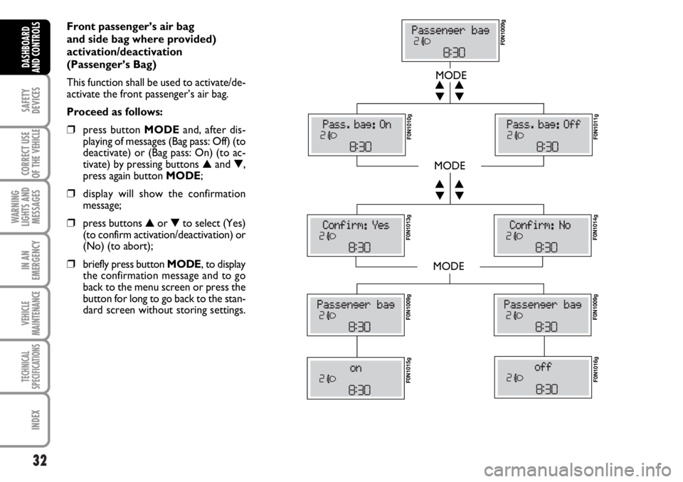
This function shall be used to activate/de-
activate the front passenger’s air bag.
Proceed as follows:
❒press button MODEand, after dis-
playing of messages (Bag pass: Off) (to
deactivate) or (Bag pass: On) (to ac-
tivate) by pressing buttons ▲and ▼,
press again button MODE;
❒display will show the confirmation
message;
❒press buttons ▲or ▼to select (Yes)
(to confirm activation/deactivation) or
(No) (to abort);
❒briefly press button MODE, to display
the confirmation message and to go
back to the menu screen or press the
button for long to go back to the stan-
dard screen without storing settings.
MODE
MODE
MODE
▼ ▲
▼ ▲
▼ ▲
▼ ▲
F0N1009g F0N1010g
F0N1011g F0N1013g
F0N1014g F0N1009gF0N1009g
F0N1015gF0N1016g
Page 40 of 238
39
SAFETY
DEVICES
CORRECT USE
OF THE
VEHICLE
WARNING
LIGHTS AND
MESSAGES
IN AN
EMERGENCY
VEHICLE
MAINTENANCE
TECHNICAL
SPECIFICATIONS
INDEX
DASHBOARD
AND CONTROLS
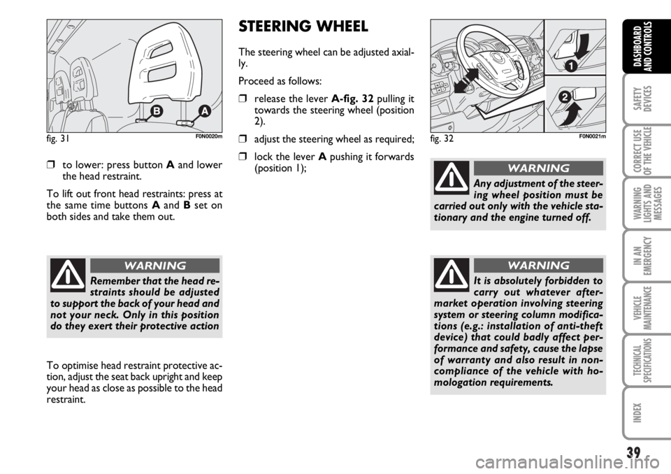
❒to lower: press button Aand lower
the head restraint.
To lift out front head restraints: press at
the same time buttons Aand Bset on
both sides and take them out.
fig. 31F0N0020m
To optimise head restraint protective ac-
tion, adjust the seat back upright and keep
your head as close as possible to the head
restraint.
Remember that the head re-
straints should be adjusted
to support the back of your head and
not your neck. Only in this position
do they exert their protective action
WARNING
STEERING WHEEL
The steering wheel can be adjusted axial-
ly.
Proceed as follows:
❒release the lever A-fig. 32pulling it
towards the steering wheel (position
2).
❒adjust the steering wheel as required;
❒lock the lever Apushing it forwards
(position 1);
fig. 32F0N0021m
Any adjustment of the steer-
ing wheel position must be
carried out only with the vehicle sta-
tionary and the engine turned off.
WARNING
It is absolutely forbidden to
carry out whatever after-
market operation involving steering
system or steering column modifica-
tions (e.g.: installation of anti-theft
device) that could badly affect per-
formance and safety, cause the lapse
of warranty and also result in non-
compliance of the vehicle with ho-
mologation requirements.
WARNING
Page 75 of 238
74
SAFETY
DEVICES
CORRECT USE
OF THE
VEHICLE
WARNING
LIGHTS AND
MESSAGES
IN AN
EMERGENCY
VEHICLE
MAINTENANCE
TECHNICAL
SPECIFICATIONS
INDEX
DASHBOARD
AND CONTROLS
IMPORTANT
Do not use abrasive detergents or sol-
vents to clean the device. To clean its ex-
ternal surface, use a wet cloth or special
products for cleaning synthetic materials.
The multimeter is installed and sealed with
lead by authorised personnel: access to
the device and relevant power and record-
ing cables is forbidden.
The vehicle owner is responsible for gov-
erning the instrument use. The inspection
must be carried out at least every two
years and will include a test to confirm
correct operation.
After the inspection, check that the plate
is updated with specified data.DOORS
CENTRAL DOOR
LOCKING/UNLOCKING SYSTEM
Locking from the outside
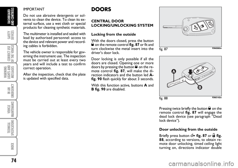
With the doors closed, press the button
Øon the remote control fig. 87or fit and
turn clockwise the metal insert into the
driver’s door lock.
Door locking is only possible if all the
doors are closed. Opening one or more
doors by pressing the button
Øon the re-
mote control fig. 87, will make the di-
rection indicators and the button led A-
fig. 90flash quickly for about 3 seconds.
With this function active, buttons Aand
B fig. 90are disabled.
fig. 87F0N0060m
Pressing twice briefly the button Øon the
remote control fig. 87will engage the
dead lock device (see paragraph “Dead
lock device”).
Door unlocking from the outside
Briefly press button
Æfig. 87or Ëfig.
88, according to versions, to obtain re-
mote door unlocking, timed ceiling light
turning on, directions indicator double
fig. 88F0N0145m
Page 77 of 238
76
SAFETY
DEVICES
CORRECT USE
OF THE
VEHICLE
WARNING
LIGHTS AND
MESSAGES
IN AN
EMERGENCY
VEHICLE
MAINTENANCE
TECHNICAL
SPECIFICATIONS
INDEX
DASHBOARD
AND CONTROLS
DEAD LOCK DEVICE
(where provided)
This safety device enables to inhibit:
❒door internal handles;
❒locking/unlocking buttons A-B fig. 90;
thus hindering doors opening from inside
the passenger’s compartment in case of at-
tempt to break-into (e.g.: window breaking).
The dead lock device guarantees the best
protection against unwanted access.
Therefore, it should be actuated every
time the vehicle is parked and left unat-
tended.
Once the dead lock device
has been actuated, doors
cannot be opened from the passen-
ger’s compartment in any way what-
soever. For this reason, make sure
there are no person left inside the ve-
hicle. If the battery of the key with
remote control is down, the dead lock
device can be deactivated only by fit-
ting the metal insert of the key in
both front door revolving plugs as de-
scribed previously: in this case the
dead lock device will stay engaged
only on the rear doors.
WARNINGDevice activation
The dead lock device is automatically ac-
tivated on every door when pressing twice
briefly the remote control button
Ø, fig.
87.
Device activation is indicated by 3 flashing
of direction indicators and flashing of the
button led A-fig. 90.
If one of the doors is not perfectly closed,
the dead lock device will not activate, thus
preventing that a person getting into the ve-
hicle from the open door remains blocked
inside the passenger’s compartment when
she/he closes the door.
Device deactivation
The device is deactivated automatically on
every door in the following cases:
❒when opening the driver’s door using
the key without remote control;
❒when unlocking doors using the re-
mote control;
❒turning the ignition key to MAR.
Page 84 of 238
83
SAFETY
DEVICES
CORRECT USE
OF THE
VEHICLE
WARNING
LIGHTS AND
MESSAGES
IN AN
EMERGENCY
VEHICLE
MAINTENANCE
TECHNICAL
SPECIFICATIONS
INDEX
DASHBOARD
AND CONTROLS
HEADLIGHTS
ADJUSTING THE HEADLIGHT
BEAM
Proper adjustment of the headlight beams
is of vital importance for your safety and
comfort and also for the other road users.
To ensure you and other drivers have the
best visibility conditions when travelling
with the headlights on, the headlights must
be set properly. Contact Fiat Dealership
to have the headlights properly adjusted.
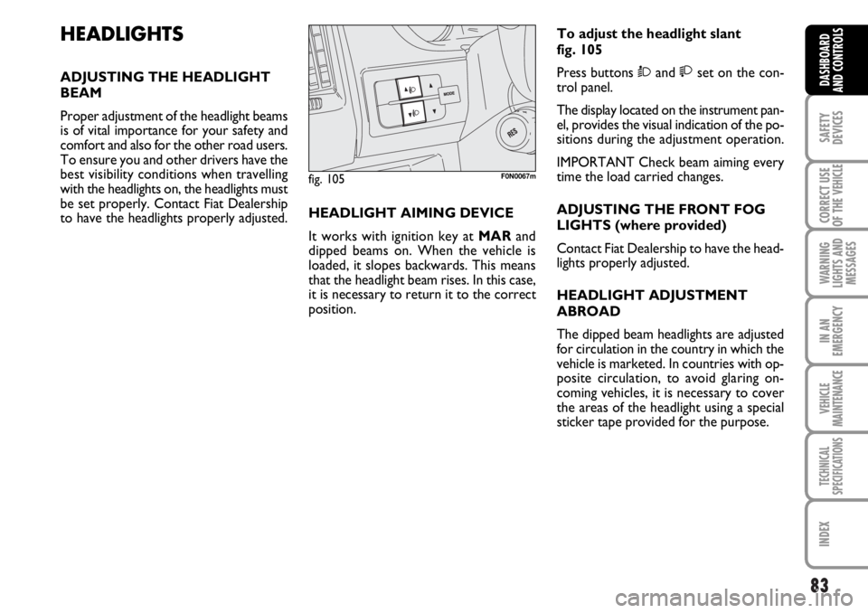
fig. 105F0N0067m
HEADLIGHT AIMING DEVICE
It works with ignition key at MARand
dipped beams on. When the vehicle is
loaded, it slopes backwards. This means
that the headlight beam rises. In this case,
it is necessary to return it to the correct
position.To adjust the headlight slant
fig. 105
Press buttons Òand set on the con-
trol panel.
The display located on the instrument pan-
el, provides the visual indication of the po-
sitions during the adjustment operation.
IMPORTANT Check beam aiming every
time the load carried changes.
ADJUSTING THE FRONT FOG
LIGHTS (where provided)
Contact Fiat Dealership to have the head-
lights properly adjusted.
HEADLIGHT ADJUSTMENT
ABROAD
The dipped beam headlights are adjusted
for circulation in the country in which the
vehicle is marketed. In countries with op-
posite circulation, to avoid glaring on-
coming vehicles, it is necessary to cover
the areas of the headlight using a special
sticker tape provided for the purpose.
Page 230 of 238
229
WARNING
LIGHTS AND
MESSAGES
DASHBOARD
AND CONTROLS
SAFETY
DEVICES
CORRECT USE
OF THE
VEHICLE
IN AN
EMERGENCY
VEHICLE
MAINTENANCE
TECHNICAL
SPECIFICATIONS
INDEX
Bodywork
– maintenance ................................... 190
– version codes ................................. 194
Bonnet .................................................... 80
Brake Assist
(brake assist in an emergency) ....... 85
Brake fluid level..................................... 182
Brakes
– fluid level ......................................... 182
– technical data ................................. 200
Bulb (replacement)
– bulb types ........................................ 150
– general instructions ....................... 150
Ceiling lights
– front................................................... 65
– rear .................................................... 66
Chassis (marking) ................................ 195
Checking fluid levels ............................ 178
Child restraint systems
(specifications for use)...................... 103
Cigar lighter .......................................... 71CO
2exhaust emissions ..................... 228
Code card............................................... 8
Consumption
– engine oil .......................................... 180
– fuel ..................................................... 227
Containing running costs .................... 120
Control buttons .................................. 66
Correct use of the vehicle ................. 115
Cruise Control .................................... 63
Current outlet....................................... 72
Dashboard............................................. 5
Dashboard and controls ..................... 4
Dead lock device
– activation/deactivation .................. 76
Digital display ......................................... 18
Dimensions ........................................... 205
Dipped beam headlights
– bulb replacement .......................... 153
– control ............................................. 58
Direction indicators
– control ............................................. 59
– front bulb replacement ................. 152
ABS ........................................................ 84
Accessories purchased by
the user ............................................... 93
Air bags (front)...................................... 108
Air bags (side)........................................ 110
Air cleaner.............................................. 184
Air vents ................................................ 42
Armrest
– front................................................... 36
Ashtray .................................................... 71
ASR ......................................................... 87
- activation/deactivation .................. 87
At the filling station .............................. 94
Automatic headlight sensor
(daylight sensor) ................................. 60
Battery
– checking the charge ...................... 184
– jump starting .................................. 140
– recharging......................................... 167
– replacing .......................................... 184
I I
N N
D D
E E
X X