sensor FIAT DUCATO 2006 Owner handbook (in English)
[x] Cancel search | Manufacturer: FIAT, Model Year: 2006, Model line: DUCATO, Model: FIAT DUCATO 2006Pages: 238, PDF Size: 3.29 MB
Page 5 of 238
4
SAFETY
DEVICES
CORRECT USE
OF THE
VEHICLE
WARNING
LIGHTS AND
MESSAGES
IN AN
EMERGENCY
VEHICLE
MAINTENANCE
TECHNICAL
SPECIFICATIONS
INDEX
DASHBOARD
AND CONTROLSDASHBOARD ........................................................................ 5
SYMBOLS ................................................................................. 6
THE FIAT CODE SYSTEM ................................................... 6
THE KEYS ................................................................................ 8
IGNITION DEVICE ................................................................ 13
INSTRUMENT PANEL ......................................................... 14
INSTRUMENTS ....................................................................... 15
DIGITAL DISPLAY ................................................................ 18
MULTIFUNCTION DISPLAY ............................................. 24
TRIP COMPUTER ................................................................. 33
FRONT SEATS ....................................................................... 35
HEAD RESTRAINTS .............................................................. 38
STEERING WHEEL ............................................................... 39
REARVIEW MIRRORS ........................................................... 40
HEATING AND VENTILATION ....................................... 42
MANUAL CLIMATE CONTROL SYSTEM .................... 46
SUPPLEMENTARY HEATER .............................................. 51
SELF-STANDING SUPPLEMENTARY HEATER............. 52
EXTERNAL LIGHTS .............................................................. 58
WINDOW WASHING......................................................... 61CRUISE CONTROL ............................................................. 63
CEILING LIGHTS .................................................................. 65
CONTROLS ........................................................................... 66
POWER SUPPLY AND FUEL CUT-OFF SWITCH....... 68
INTERIOR FITTINGS ............................................................ 69
MULTIMETER .......................................................................... 73
DOORS .................................................................................... 74
POWER WINDOWS/WINDOW WINDERS .............. 79
BONNET .................................................................................. 80
ROOF RACK/SKI RACK ..................................................... 82
HEADLIGHTS .......................................................................... 83
ABS SYSTEM ........................................................................... 84
ESP SYSTEM ............................................................................ 85
EOBD SYSTEM ....................................................................... 88
PARKING SENSORS ............................................................ 89
SOUND SYSTEM .................................................................... 92
ACCESSORIES PURCHASED BY THE OWNER .......... 93
AT THE FILLING STATION .............................................. 94
PROTECTING THE ENVIRONMENT ............................. 95
D D
A A
S S
H H
B B
O O
A A
R R
D D
A A
N N
D D
C C
O O
N N
T T
R R
O O
L L
S S
Page 27 of 238
26
SAFETY
DEVICES
CORRECT USE
OF THE
VEHICLE
WARNING
LIGHTS AND
MESSAGES
IN AN
EMERGENCY
VEHICLE
MAINTENANCE
TECHNICAL
SPECIFICATIONS
INDEX
DASHBOARD
AND CONTROLS
Day
YearMonth
Deutsch
Français
English
Español
Italiano
Nederland
Português Example:
fig. 21 Example:
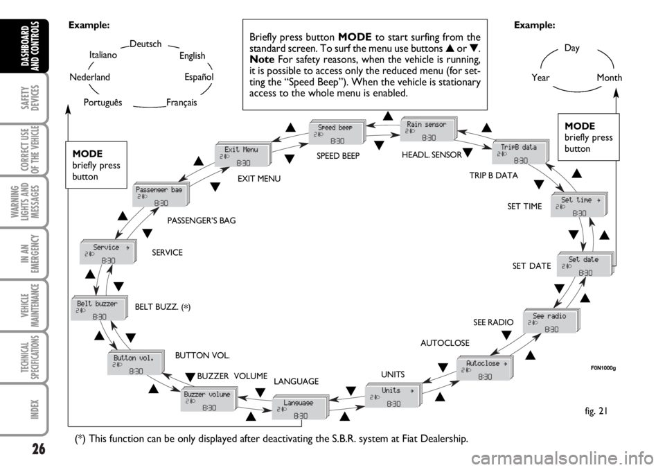
Briefly press button MODEto start surfing from the
standard screen. To surf the menu use buttons ▲or ▼.
NoteFor safety reasons, when the vehicle is running,
it is possible to access only the reduced menu (for set-
ting the “Speed Beep”). When the vehicle is stationary
access to the whole menu is enabled.
F0N1000g
MODE
briefly press
button
▲
▼
EXIT MENUSPEED BEEPHEADL. SENSOR
SET TIME
SET DATE
SEE RADIO
AUTOCLOSE
UNITS
LANGUAGE BUZZER VOLUME BUTTON VOL. SERVICEPASSENGER’S BAG
(*) This function can be only displayed after deactivating the S.B.R. system at Fiat Dealership.
TRIP B DATA
MODE
briefly press
button
▲
▼▲
▼▲
▼
▲
▼
▲ ▼
▲ ▼ ▲
▼
▲
▼
▲
▼
▲▼
▲▼
▲▼
▲▼▲ ▼
BELT BUZZ. (*)
Page 28 of 238

27
SAFETY
DEVICES
CORRECT USE
OF THE
VEHICLE
WARNING
LIGHTS AND
MESSAGES
IN AN
EMERGENCY
VEHICLE
MAINTENANCE
TECHNICAL
SPECIFICATIONS
INDEX
DASHBOARD
AND CONTROLS
– briefly press button MODE to go back
to the menu screen or press the button
for long to go back to the standard screen
without storing settings.
To cancel the setting, proceed as follows:
– briefly press button MODE: (On) will
flash on the display;
– press button ▼: (Off) will flash on the
display;
– briefly press button MODEto go back
to the menu screen or press the button
for long to go back to the standard screen
without storing settings.
Headlight sensor sensitivity
adjustment (where provided)
With this function it is possible to adjust
the light sensor sensitivity according to 3
levels.
To set the required sensitivity level pro-
ceed as follows:
– briefly press button MODE, the previ-
ously set sensitivity “level” will flash on the
display; Speed limit (Speed Beep)
With this function it is possible to set the
vehicle speed limit (km/h or mph); when
this limit is exceeded the driver is imme-
diately alerted (see section “Warning lights
and messages”).
To set the speed limit, proceed as follows:
– briefly press button MODE, the display
will show the wording (Speed Beep);
– press button ▲or ▼to select speed
limit activation (On) or deactivation (Off);
– if the function has been activated (On),
press buttons ▲or ▼to select the re-
quired speed limit and then press MODE
to confirm.
NoteThe possible setting is between 30 and
200 km/h, or between 20 and 125 mph de-
pending on the unit set previously (see para-
graph “Setting the distance unit (Units)”) de-
scribed later. Every press on button
▲/ ▼increases/decreases by 5 units. Keeping the
button ▲/ ▼pressed obtains the automat-
ic fast increase or decrease. When you are
near the required setting complete adjust-
ment by single presses.
– press button ▲or ▼for setting;
– briefly press button MODEto go back
to the menu screen or press the button
for long to go back to the standard screen
without storing settings.
Trip B On/Off (tripB data)
Through this option it is possible to acti-
vate (On) or deactivate (Off) the Trip B
(partial trip).
For further information see “Trip com-
puter”.
For activation / deactivation, proceed as
follows:
– briefly press button MODE: (On) or
(Off) will flash on the display (according to
previous setting);
– press button ▲or ▼for setting;
– briefly press button MODEto go back
to the menu screen or press the button
for long to go back to the standard screen
without storing settings.
Page 61 of 238
60
SAFETY
DEVICES
CORRECT USE
OF THE
VEHICLE
WARNING
LIGHTS AND
MESSAGES
IN AN
EMERGENCY
VEHICLE
MAINTENANCE
TECHNICAL
SPECIFICATIONS
INDEX
DASHBOARD
AND CONTROLS
“FOLLOW ME HOME”
DEVICE
This function allows the illumination of the
space in front of the vehicle for a preset
period of time.
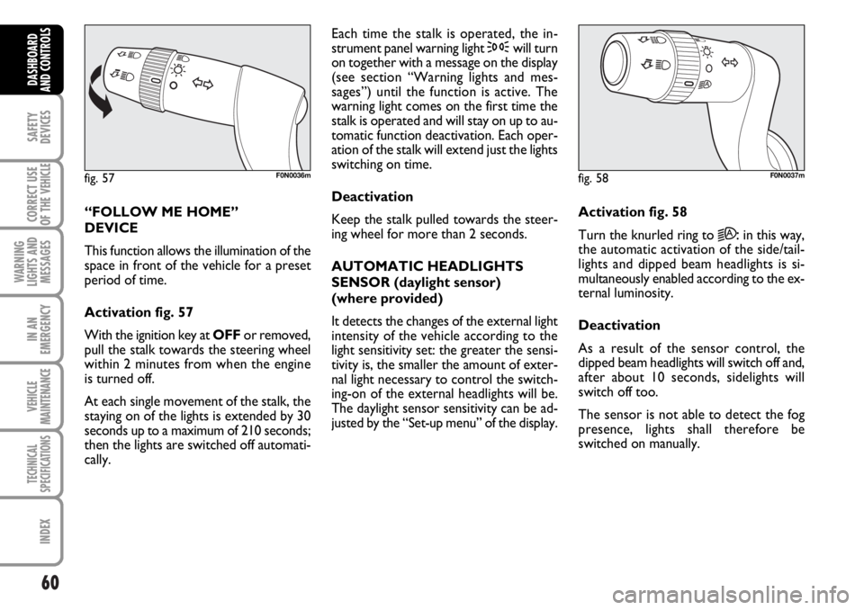
Activation fig. 57
With the ignition key at OFFor removed,
pull the stalk towards the steering wheel
within 2 minutes from when the engine
is turned off.
At each single movement of the stalk, the
staying on of the lights is extended by 30
seconds up to a maximum of 210 seconds;
then the lights are switched off automati-
cally. Each time the stalk is operated, the in-
strument panel warning light 3will turn
on together with a message on the display
(see section “Warning lights and mes-
sages”) until the function is active. The
warning light comes on the first time the
stalk is operated and will stay on up to au-
tomatic function deactivation. Each oper-
ation of the stalk will extend just the lights
switching on time.
Deactivation
Keep the stalk pulled towards the steer-
ing wheel for more than 2 seconds.
AUTOMATIC HEADLIGHTS
SENSOR (daylight sensor)
(where provided)
It detects the changes of the external light
intensity of the vehicle according to the
light sensitivity set: the greater the sensi-
tivity is, the smaller the amount of exter-
nal light necessary to control the switch-
ing-on of the external headlights will be.
The daylight sensor sensitivity can be ad-
justed by the “Set-up menu” of the display.Activation fig. 58
Turn the knurled ring to
2A:in this way,
the automatic activation of the side/tail-
lights and dipped beam headlights is si-
multaneously enabled according to the ex-
ternal luminosity.
Deactivation
As a result of the sensor control, the
dipped beam headlights will switch off and,
after about 10 seconds, sidelights will
switch off too.
The sensor is not able to detect the fog
presence, lights shall therefore be
switched on manually.
fig. 57F0N0036mfig. 58F0N0037m
Page 63 of 238
62
SAFETY
DEVICES
CORRECT USE
OF THE
VEHICLE
WARNING
LIGHTS AND
MESSAGES
IN AN
EMERGENCY
VEHICLE
MAINTENANCE
TECHNICAL
SPECIFICATIONS
INDEX
DASHBOARD
AND CONTROLS
RAIN SENSOR
(where provided)
The rain sensor is located behind the dri-
ving mirror in contact with the windscreen
and has the purpose of automatically ad-
just, during the intermittent operation, the
frequency of the windscreen wiper
strokes as to the rain intensity.
IMPORTANT Keep clean the glass in the
sensor area.
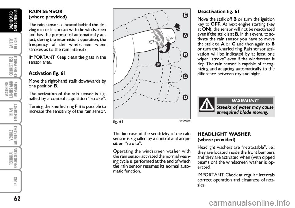
Activation fig. 61
Move the right-hand stalk downwards by
one position B.
The activation of the rain sensor is sig-
nalled by a control acquisition “stroke”.
Turning the knurled ring Fit is possible to
increase the sensitivity of the rain sensor.
The increase of the sensitivity of the rain
sensor is signalled by a control and acqui-
sition “stroke”.
Operating the windscreen washer with
the rain sensor activated the normal wash-
ing cycle is performed at the end of which
the rain sensor resumes its normal auto-
matic function.HEADLIGHT WASHER
(where provided)
Headlight washers are “retractable”, i.e.:
they are located inside the front bumpers
and they are activated when (with dipped
beams on) the windscreen washer is op-
erated.
IMPORTANT Check at regular intervals
correct operation and cleanness of noz-
zles. Deactivation fig. 61
Move the stalk off Bor turn the ignition
key to OFF. At next engine starting (key
at ON), the sensor will not be reactivated
even if the stalk is at B. In this event, to ac-
tivate the rain sensor you have to move
the stalk to Aor Cand then again to B
or turn the knurled ring. Rain sensor acti-
vation will be indicated by at least one
wiper “stroke” even if the windscreen is
dry. The rain sensor is capable of recog-
nizing and adapting automatically to the
difference between day and night.
fig. 61F0N0038m
Streaks of water may cause
unrequired blade moving.
WARNING
Page 90 of 238
89
SAFETY
DEVICES
CORRECT USE
OF THE
VEHICLE
WARNING
LIGHTS AND
MESSAGES
IN AN
EMERGENCY
VEHICLE
MAINTENANCE
TECHNICAL
SPECIFICATIONS
INDEX
DASHBOARD
AND CONTROLS
PARKING SENSORS
(where provided)
Parking sensors are located in the rear
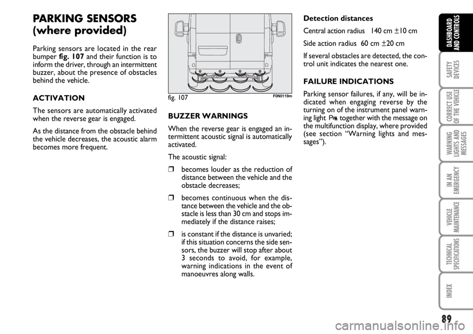
bumper fig. 107and their function is to
inform the driver, through an intermittent
buzzer, about the presence of obstacles
behind the vehicle.
ACTIVATION
The sensors are automatically activated
when the reverse gear is engaged.
As the distance from the obstacle behind
the vehicle decreases, the acoustic alarm
becomes more frequent. BUZZER WARNINGS
When the reverse gear is engaged an in-
termittent acoustic signal is automatically
activated.
The acoustic signal:
❒becomes louder as the reduction of
distance between the vehicle and the
obstacle decreases;
❒becomes continuous when the dis-
tance between the vehicle and the ob-
stacle is less than 30 cm and stops im-
mediately if the distance raises;
❒is constant if the distance is unvaried;
if this situation concerns the side sen-
sors, the buzzer will stop after about
3 seconds to avoid, for example,
warning indications in the event of
manoeuvres along walls.Detection distances
Central action radius 140 cm ±10 cm
Side action radius 60 cm ±20 cm
If several obstacles are detected, the con-
trol unit indicates the nearest one.
FAILURE INDICATIONS
Parking sensor failures, if any, will be in-
dicated when engaging reverse by the
turning on of the instrument panel warn-
ing light
ttogether with the message on
the multifunction display, where provided
(see section “Warning lights and mes-
sages”).
fig. 107F0N0119m
Page 91 of 238
90
SAFETY
DEVICES
CORRECT USE
OF THE
VEHICLE
WARNING
LIGHTS AND
MESSAGES
IN AN
EMERGENCY
VEHICLE
MAINTENANCE
TECHNICAL
SPECIFICATIONS
INDEX
DASHBOARD
AND CONTROLS
For proper operation, the
parking sensors shall always
be clean from mud, dirt, snow
or ice. When cleaning the sen-
sors, take the utmost care to prevent
their damaging; do not use therefore
dry or rough clothes. Sensors shall be
washed with clean water and vehicle
detergent, if required.
Parking manoeuvres howev-
er are always under the dri-
ver’s responsibility that shall always
check the absence of people (spe-
cially children) or animals in the ma-
noeuvre space. This system is just a
help for the driver but she/he shall
never reduce attention during dan-
gerous manoeuvres even if performed
at low speed.
WARNINGOPERATION WITH
TRAILER
Parking sensor operation is deactivated au-
tomatically when the trailer electric cable
plug is fitted into the vehicle tow hook
socket.
Sensors are reactivated when removing
the trailer cable plug.
In washing stations, clean sensors quickly
keeping the vapour jet/high pressure
washing nozzles at 10 cm at least from the
sensors.
Page 92 of 238

91
SAFETY
DEVICES
CORRECT USE
OF THE
VEHICLE
WARNING
LIGHTS AND
MESSAGES
IN AN
EMERGENCY
VEHICLE
MAINTENANCE
TECHNICAL
SPECIFICATIONS
INDEX
DASHBOARD
AND CONTROLS
GENERAL WARNINGS
❒When parking, take the utmost care
to obstacles that may be set above or
under the sensors.
❒Objects set close to the vehicle, un-
der certain circumstances are not de-
tected and could therefore cause
damages to the vehicle or be dam-
aged.
Below are listed some conditions that
could affect the parking system perfor-
mance:
❒Reduced sensor sensitivity or re-
duced parking system performance
could be due to the presence on the
sensor surface of: ice, snow, mud,
multiple painting.
❒The sensor detects a non-existent ob-
ject (“echo disturbances”) caused by
disturbances of mechanical nature,
e.g.: vehicle washing, rain (extreme
wind conditions), hail.
❒Indications sent by the sensors can al-
so be altered by ultrasound systems
(e.g.: truck pneumatic brakes or pneu-
matic hammers) set nearby the vehi-
cle.
❒Parking system performance could al-
so be affected by sensor position. For
instance, when trimming is changed
(due to wear of shock absorbers, sus-
pensions) or when changing tyres,
loading excessively the vehicle, car-
rying out specific tuning for lowering
the vehicle.
❒Obstacle detection at the top of the
vehicle (specially for vans or chassis
cabs) could not be guaranteed since
the system detects obstacles that can
strike the bottom of the vehicle.
Page 128 of 238
127
IN AN
EMERGENCY
VEHICLE
MAINTENANCE
TECHNICAL
SPECIFICATIONS
INDEX
DASHBOARD
AND CONTROLS
SAFETY
DEVICES
CORRECT USE
OF THE
VEHICLE
WARNING
LIGHTS AND
MESSAGES
GENERAL WARNINGS ...................................................... 128
LOW BRAKE FLUID.............................................................. 128
HANDBRAKE ON ................................................................. 128
AIR BAG FAILURE ................................................................. 129
ENGINE COOLANT
HIGH TEMPERATURE .......................................................... 129
LOW BATTERY CHARGE .................................................. 130
LOW ENGINE OIL PRESSURE........................................... 130
EXHAUSTED OIL ................................................................. 130
INCOMPLETE DOOR LOCKING..................................... 131
SEAT BELTS NOT FASTENED ........................................... 131
EBD SYSTEM FAILURE ......................................................... 131
INJECTION SYSTEM FAILURE .......................................... 132
FRONT PASSENGER AIR BAG DEACTIVATED .......... 132
ABS SYSTEM FAILURE .......................................................... 132
FUEL RESERVE......................................................................... 132
GLOW PLUG WARMING ................................................. 133
GLOW PLUG WARMING FAILURE ................................ 133
WATER IN DIESEL FUEL FILTER ..................................... 133
VEHICLE PROTECTION SYSTEM FAILURE
FIAT CODE ............................................................................. 133
EXTERNAL LIGHTS FAILURE ............................................ 134
REAR FOGLIGHTS ................................................................ 134
GENERIC FAILURE INDICATION .................................. 134
ESP - ASR SYSTEM FAILURE .............................................. 135
DIESEL PARTICULATE FILTER CLOGGED ................... 135BRAKE PAD WEAR .............................................................. 135
HILL HOLDER FAILURE ..................................................... 135
PARKING SENSOR FAILURE ............................................. 136
SIDELIGHTS AND LOW BEAMS ...................................... 136
FOLLOW ME HOME ............................................................ 136
FRONT FOG LIGHTS ........................................................... 136
LEFT-HAND DIRECTION INDICATOR ........................ 136
RIGHT-HAND DIRECTION INDICATOR .................... 137
CRUISE CONTROL ............................................................. 137
MAIN BEAM HEADLIGHTS ................................................ 137
ASR SYSTEM ........................................................................... 137
POWER STEERING FAILURE ............................................. 137
POSSIBLE PRESENCE OF ICE ON THE ROAD ............ 138
LIMITED RANGE ................................................................... 138
SPEED LIMIT EXCEEDED ................................................... 138
ENGINE COOLANT LEVEL................................................. 138
SCHEDULED SERVICING ................................................... 138
SELF-LEVELLING SUSPENSIONS FAILURE .................... 138
AUTOMATIC TRANSMISSION FAILURE/
MAX. GEARBOX OIL TEMPERATURE ........................... 138
W W
A A
R R
N N
I I
N N
G G
L L
I I
G G
H H
T T
S S
A A
N N
D D
M M
E E
S S
S S
A A
G G
E E
S S
Page 135 of 238

134
IN AN
EMERGENCY
VEHICLE
MAINTENANCE
TECHNICAL
SPECIFICATIONS
INDEX
DASHBOARD
AND CONTROLS
SAFETY
DEVICES
CORRECT USE
OF THE
VEHICLE
WARNING
LIGHTS AND
MESSAGES
GENERIC FAILURE
INDICATION
(amber)
The warning light turns on in the follow-
ing circumstances.
Engine oil pressure
sensor failure
The warning light comes on when the en-
gine oil pressure sensor is faulty. Contact
Fiat Dealership as soon as possible.
Inertial fuel cut-off switch
intervened
The warning light comes on when the in-
ertial fuel cut-off switch is triggered.
The display will show the dedicated mes-
sage.
è
EXTERNAL LIGHT
FAILURE (amber)
The warning light turns on
when one of the following lights
is failing:
– sidelights
– brake lights
– rear fog guards
– direction indicators.
The failure referring to these lights could
be: one or more blown bulbs, a blown
protection fuse or an electric connection
cut-off.
On certain versions the dedicated message
is displayed.
W
REAR FOG LIGHTS
(amber)
The warning light turns on
when the rear fog lights are turned on.
4
Rain sensor failure
(versions with multifunction
display)
The warning light on the dial turns on
when the rain sensor is faulty. Contact Fi-
at Dealership.
The display will show the dedicated mes-
sage.
Parking sensor failure
(versions with multifunction
display)
See what described for warning light
t.