sensor FIAT DUCATO 2007 Owner handbook (in English)
[x] Cancel search | Manufacturer: FIAT, Model Year: 2007, Model line: DUCATO, Model: FIAT DUCATO 2007Pages: 282, PDF Size: 4.49 MB
Page 5 of 282
4
SAFETY
DEVICES
CORRECT USE
OF THE
VEHICLE
WARNING
LIGHTS AND
MESSAGES
IN AN
EMERGENCY
VEHICLE
MAINTENANCE
TECHNICAL
SPECIFICATIONS
INDEX
DASHBOARD
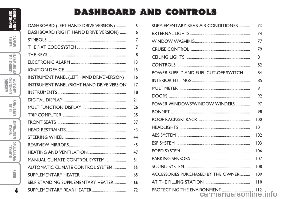
AND CONTROLSDASHBOARD (LEFT HAND DRIVE VERSION) .......... 5
DASHBOARD (RIGHT HAND DRIVE VERSION) ...... 6
SYMBOLS ................................................................................. 7
THE FIAT CODE SYSTEM ................................................... 7
THE KEYS ................................................................................ 8
ELECTRONIC ALARM ......................................................... 13
IGNITION DEVICE ................................................................ 15
INSTRUMENT PANEL (LEFT HAND DRIVE VERSION) 16
INSTRUMENT PANEL (RIGHT HAND DRIVE VERSION) 17
INSTRUMENTS ....................................................................... 18
DIGITAL DISPLAY ................................................................ 21
MULTIFUNCTION DISPLAY ............................................. 26
TRIP COMPUTER ................................................................. 35
FRONT SEATS ....................................................................... 37
HEAD RESTRAINTS .............................................................. 43
STEERING WHEEL ............................................................... 44
REARVIEW MIRRORS ........................................................... 45
HEATING AND VENTILATION ....................................... 47
MANUAL CLIMATE CONTROL SYSTEM .................... 51
AUTOMATIC CLIMATE CONTROL SYSTEM .............. 55
SUPPLEMENTARY HEATER .............................................. 65
SELF-STANDING SUPPLEMENTARY HEATER............. 66
SUPPLEMENTARY REAR HEATER ................................... 72SUPPLEMENTARY REAR AIR CONDITIONER ............ 73
EXTERNAL LIGHTS .............................................................. 74
WINDOW WASHING......................................................... 77
CRUISE CONTROL ............................................................. 79
CEILING LIGHTS .................................................................. 81
CONTROLS ........................................................................... 82
POWER SUPPLY AND FUEL CUT-OFF SWITCH....... 84
INTERIOR FITTINGS ............................................................ 85
MULTIMETER .......................................................................... 91
DOORS .................................................................................... 92
POWER WINDOWS/WINDOW WINDERS .............. 97
BONNET .................................................................................. 98
ROOF RACK/SKI RACK ..................................................... 100
HEADLIGHTS .......................................................................... 101
ABS SYSTEM ........................................................................... 102
ESP SYSTEM ............................................................................ 103
EOBD SYSTEM ....................................................................... 106
PARKING SENSORS ............................................................ 107
SOUND SYSTEM .................................................................... 108
ACCESSORIES PURCHASED BY THE OWNER .......... 109
AT THE FILLING STATION .............................................. 110
PROTECTING THE ENVIRONMENT ............................. 112
D D
A A
S S
H H
B B
O O
A A
R R
D D
A A
N N
D D
C C
O O
N N
T T
R R
O O
L L
S S
Page 14 of 282
13
SAFETY
DEVICES
CORRECT USE
OF THE
VEHICLE
WARNING
LIGHTS AND
MESSAGES
IN AN
EMERGENCY
VEHICLE
MAINTENANCE
TECHNICAL
SPECIFICATIONS
INDEX
DASHBOARD
AND CONTROLS
ELECTRONIC ALARM
(where provided)
The alarm, provided in addition to all the
remote control functions described pre-
viously is controlled by the receiver set
under the dashboard near the fuse box.
WHEN THE ALARM
IS TRIGGERED
The alarm comes into action in the fol-
lowing cases:
❒unlawful opening of one of the doors or
engine bonnet (perimetral protection);
❒attempt to start the engine (key turned
to MAR);
❒battery cables cutting;
❒abnormal raising/sloping of the vehicle.
Depending on the markets, the cutting in
of the alarm causes operation of the siren
and direction indicators (for about 26 sec-
onds). The ways of operating and the num-
ber of cycles may vary depending on the
markets.
A maximum number of sound/sight cycles
is however envisaged; at the end of these
cycles the system will resume its regular
operation.Anti-raising protection can be cut off by
pressing the corresponding button (see
paragraph “Anti-raising sensor” on the fol-
lowing pages).
IMPORTANT The engine immobiliser
function is guaranteed by the Fiat CODE
system, which is automatically activated
when the key is removed from the igni-
tion device.
HOW TO ACTIVATE
THE ALARM
With the doors, bonnet and load com-
partment shut and ignition key toSTOP
or removed, point the key with remote
control or removed, point the key with
remote control in the direction of the ve-
hicle, then press and release the button
“lock”.
With the exception of certain markets,
the system sounds a “beep” and the doors
are locked.
Engagement of the alarm is preceded by
a self-diagnostic test. If a fault is detected
the system sounds a further warning
“beep”.
In this case, switch the alarm off by press-
ing button “door unlock/load compart-
ment unlock”, check that the doors and
bonnet are properly shut, then switch the
alarm on again by pressing button “lock”.The door and bonnet not properly shut
will be excluded from the alarm control.
If the doors, bonnet and load compart-
ment are shut correctly and the warning
“beep” is repeated, the system self-diag-
nostics has detected a system operating
fault. It is therefore necessary to contact
a Fiat Dealership.
IMPORTANT Operating the central door
locking system with the metal insert of the
key will not activate the alarm.
IMPORTANT The alarm is built in com-
pliance with the law and regulations of the
different destination countries.
HOW TO DEACTIVATE
THE ALARM
Press button “door unlock/load compart-
ment unlock” of the key with remote con-
trol.
The system will react as follows (with the
exception of certain markets):
❒two brief flashes of the direction in-
dicators;
❒two brief “beeps”;
❒door unlocking.
IMPORTANT Operating the central door
opening system with the metal insert of
the key will not activate the alarm.
Page 15 of 282
14
SAFETY
DEVICES
CORRECT USE
OF THE
VEHICLE
WARNING
LIGHTS AND
MESSAGES
IN AN
EMERGENCY
VEHICLE
MAINTENANCE
TECHNICAL
SPECIFICATIONS
INDEX
DASHBOARD
AND CONTROLS
ANTI-RAISING SENSOR
The anti-raising sensor detects any ab-
normal vehicle raising/sloping, even partial
(e.g.: attempt to remove a wheel).
This sensor can detect the smallest vehi-
cle sideslip angle changes, both longitudi-
nally and transversally.
Sideslip angle changes lower than 0.5°/min.
(e.g.: slow tyre flattening) are not consid-
ered.
Anti-raising protection
deactivation
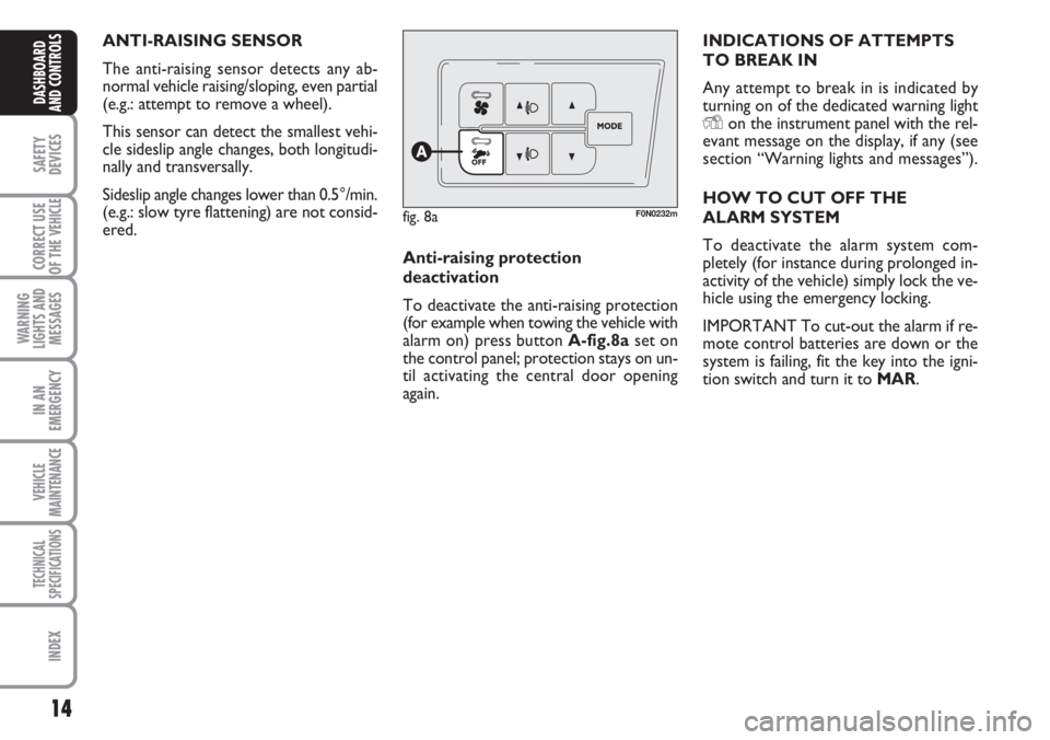
To deactivate the anti-raising protection
(for example when towing the vehicle with
alarm on) press button A-fig.8a set on
the control panel; protection stays on un-
til activating the central door opening
again.
fig. 8aF0N0232m
INDICATIONS OF ATTEMPTS
TO BREAK IN
Any attempt to break in is indicated by
turning on of the dedicated warning light
Yon the instrument panel with the rel-
evant message on the display, if any (see
section “Warning lights and messages”).
HOW TO CUT OFF THE
ALARM SYSTEM
To deactivate the alarm system com-
pletely (for instance during prolonged in-
activity of the vehicle) simply lock the ve-
hicle using the emergency locking.
IMPORTANT To cut-out the alarm if re-
mote control batteries are down or the
system is failing, fit the key into the igni-
tion switch and turn it to MAR.
Page 29 of 282
28
SAFETY
DEVICES
CORRECT USE
OF THE
VEHICLE
WARNING
LIGHTS AND
MESSAGES
IN AN
EMERGENCY
VEHICLE
MAINTENANCE
TECHNICAL
SPECIFICATIONS
INDEX
DASHBOARD
AND CONTROLS
Day
YearMonth
Deutsch
Français
English
Español
Italiano
Nederland
Português Example:
fig. 21 Example:
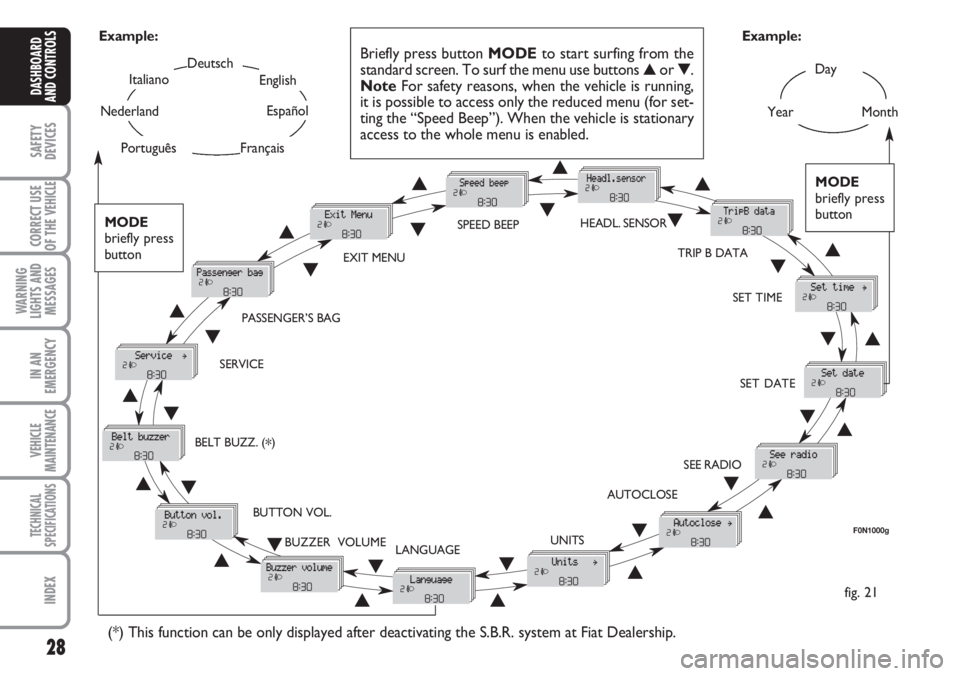
Briefly press button MODEto start surfing from the
standard screen. To surf the menu use buttons ▲or ▼.
NoteFor safety reasons, when the vehicle is running,
it is possible to access only the reduced menu (for set-
ting the “Speed Beep”). When the vehicle is stationary
access to the whole menu is enabled.
F0N1000g
MODE
briefly press
button
▲
▼
EXIT MENUSPEED BEEPHEADL. SENSOR
SET TIME
SET DATE
SEE RADIO
AUTOCLOSE
UNITS
LANGUAGE BUZZER VOLUME BUTTON VOL. SERVICEPASSENGER’S BAG
(*) This function can be only displayed after deactivating the S.B.R. system at Fiat Dealership.
TRIP B DATA
MODE
briefly press
button
▲
▼▲
▼▲
▼
▲
▼
▲ ▼
▲ ▼ ▲
▼
▲
▼
▲
▼
▲▼
▲▼
▲▼
▲▼▲ ▼
BELT BUZZ. (*)
Page 30 of 282
29
SAFETY
DEVICES
CORRECT USE
OF THE
VEHICLE
WARNING
LIGHTS AND
MESSAGES
IN AN
EMERGENCY
VEHICLE
MAINTENANCE
TECHNICAL
SPECIFICATIONS
INDEX
DASHBOARD
AND CONTROLS
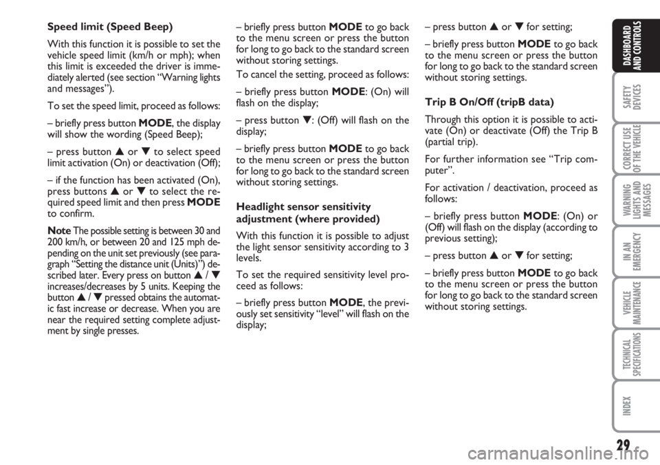
– briefly press button MODE to go back
to the menu screen or press the button
for long to go back to the standard screen
without storing settings.
To cancel the setting, proceed as follows:
– briefly press button MODE: (On) will
flash on the display;
– press button ▼: (Off) will flash on the
display;
– briefly press button MODEto go back
to the menu screen or press the button
for long to go back to the standard screen
without storing settings.
Headlight sensor sensitivity
adjustment (where provided)
With this function it is possible to adjust
the light sensor sensitivity according to 3
levels.
To set the required sensitivity level pro-
ceed as follows:
– briefly press button MODE, the previ-
ously set sensitivity “level” will flash on the
display; Speed limit (Speed Beep)
With this function it is possible to set the
vehicle speed limit (km/h or mph); when
this limit is exceeded the driver is imme-
diately alerted (see section “Warning lights
and messages”).
To set the speed limit, proceed as follows:
– briefly press button MODE, the display
will show the wording (Speed Beep);
– press button ▲or ▼to select speed
limit activation (On) or deactivation (Off);
– if the function has been activated (On),
press buttons ▲or ▼to select the re-
quired speed limit and then press MODE
to confirm.
NoteThe possible setting is between 30 and
200 km/h, or between 20 and 125 mph de-
pending on the unit set previously (see para-
graph “Setting the distance unit (Units)”) de-
scribed later. Every press on button
▲/ ▼increases/decreases by 5 units. Keeping the
button ▲/ ▼pressed obtains the automat-
ic fast increase or decrease. When you are
near the required setting complete adjust-
ment by single presses.
– press button ▲or ▼for setting;
– briefly press button MODEto go back
to the menu screen or press the button
for long to go back to the standard screen
without storing settings.
Trip B On/Off (tripB data)
Through this option it is possible to acti-
vate (On) or deactivate (Off) the Trip B
(partial trip).
For further information see “Trip com-
puter”.
For activation / deactivation, proceed as
follows:
– briefly press button MODE: (On) or
(Off) will flash on the display (according to
previous setting);
– press button ▲or ▼for setting;
– briefly press button MODEto go back
to the menu screen or press the button
for long to go back to the standard screen
without storing settings.
Page 77 of 282
76
SAFETY
DEVICES
CORRECT USE
OF THE
VEHICLE
WARNING
LIGHTS AND
MESSAGES
IN AN
EMERGENCY
VEHICLE
MAINTENANCE
TECHNICAL
SPECIFICATIONS
INDEX
DASHBOARD
AND CONTROLS
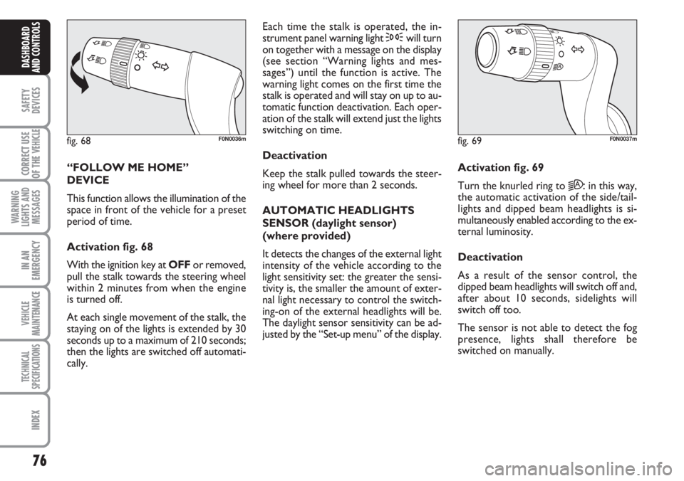
“FOLLOW ME HOME”
DEVICE
This function allows the illumination of the
space in front of the vehicle for a preset
period of time.
Activation fig. 68
With the ignition key at OFFor removed,
pull the stalk towards the steering wheel
within 2 minutes from when the engine
is turned off.
At each single movement of the stalk, the
staying on of the lights is extended by 30
seconds up to a maximum of 210 seconds;
then the lights are switched off automati-
cally. Each time the stalk is operated, the in-
strument panel warning light 3will turn
on together with a message on the display
(see section “Warning lights and mes-
sages”) until the function is active. The
warning light comes on the first time the
stalk is operated and will stay on up to au-
tomatic function deactivation. Each oper-
ation of the stalk will extend just the lights
switching on time.
Deactivation
Keep the stalk pulled towards the steer-
ing wheel for more than 2 seconds.
AUTOMATIC HEADLIGHTS
SENSOR (daylight sensor)
(where provided)
It detects the changes of the external light
intensity of the vehicle according to the
light sensitivity set: the greater the sensi-
tivity is, the smaller the amount of exter-
nal light necessary to control the switch-
ing-on of the external headlights will be.
The daylight sensor sensitivity can be ad-
justed by the “Set-up menu” of the display.Activation fig. 69
Turn the knurled ring to
2A:in this way,
the automatic activation of the side/tail-
lights and dipped beam headlights is si-
multaneously enabled according to the ex-
ternal luminosity.
Deactivation
As a result of the sensor control, the
dipped beam headlights will switch off and,
after about 10 seconds, sidelights will
switch off too.
The sensor is not able to detect the fog
presence, lights shall therefore be
switched on manually.
fig. 68F0N0036mfig. 69F0N0037m
Page 79 of 282
78
SAFETY
DEVICES
CORRECT USE
OF THE
VEHICLE
WARNING
LIGHTS AND
MESSAGES
IN AN
EMERGENCY
VEHICLE
MAINTENANCE
TECHNICAL
SPECIFICATIONS
INDEX
DASHBOARD
AND CONTROLS
RAIN SENSOR
(where provided)
The rain sensor is located behind the dri-
ving mirror in contact with the windscreen
and has the purpose of automatically ad-
just, during the intermittent operation, the
frequency of the windscreen wiper
strokes as to the rain intensity.
IMPORTANT Keep clean the glass in the
sensor area.
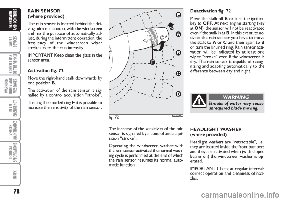
Activation fig. 72
Move the right-hand stalk downwards by
one position B.
The activation of the rain sensor is sig-
nalled by a control acquisition “stroke”.
Turning the knurled ring Fit is possible to
increase the sensitivity of the rain sensor.
The increase of the sensitivity of the rain
sensor is signalled by a control and acqui-
sition “stroke”.
Operating the windscreen washer with
the rain sensor activated the normal wash-
ing cycle is performed at the end of which
the rain sensor resumes its normal auto-
matic function.HEADLIGHT WASHER
(where provided)
Headlight washers are “retractable”, i.e.:
they are located inside the front bumpers
and they are activated when (with dipped
beams on) the windscreen washer is op-
erated.
IMPORTANT Check at regular intervals
correct operation and cleanness of noz-
zles. Deactivation fig. 72
Move the stalk off Bor turn the ignition
key to OFF. At next engine starting (key
at ON), the sensor will not be reactivated
even if the stalk is at B. In this event, to ac-
tivate the rain sensor you have to move
the stalk to Aor Cand then again to B
or turn the knurled ring. Rain sensor acti-
vation will be indicated by at least one
wiper “stroke” even if the windscreen is
dry. The rain sensor is capable of recog-
nizing and adapting automatically to the
difference between day and night.
fig. 72F0N0038m
Streaks of water may cause
unrequired blade moving.
WARNING
Page 108 of 282
107
SAFETY
DEVICES
CORRECT USE
OF THE
VEHICLE
WARNING
LIGHTS AND
MESSAGES
IN AN
EMERGENCY
VEHICLE
MAINTENANCE
TECHNICAL
SPECIFICATIONS
INDEX
DASHBOARD
AND CONTROLS
PARKING SENSORS
(where provided)
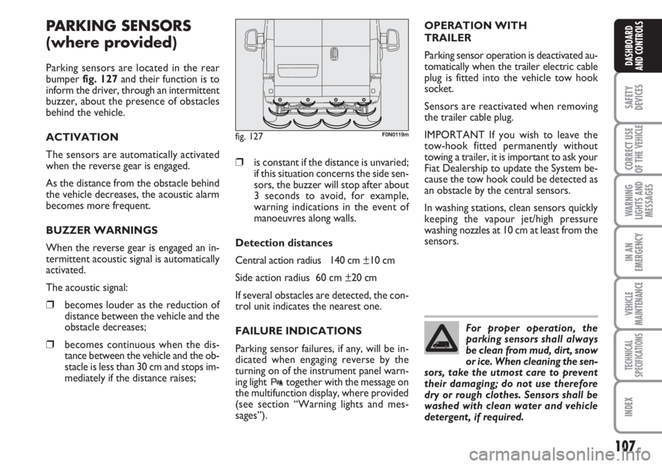
Parking sensors are located in the rear
bumper fig. 127and their function is to
inform the driver, through an intermittent
buzzer, about the presence of obstacles
behind the vehicle.
ACTIVATION
The sensors are automatically activated
when the reverse gear is engaged.
As the distance from the obstacle behind
the vehicle decreases, the acoustic alarm
becomes more frequent.
BUZZER WARNINGS
When the reverse gear is engaged an in-
termittent acoustic signal is automatically
activated.
The acoustic signal:
❒becomes louder as the reduction of
distance between the vehicle and the
obstacle decreases;
❒becomes continuous when the dis-
tance between the vehicle and the ob-
stacle is less than 30 cm and stops im-
mediately if the distance raises;
❒is constant if the distance is unvaried;
if this situation concerns the side sen-
sors, the buzzer will stop after about
3 seconds to avoid, for example,
warning indications in the event of
manoeuvres along walls.
Detection distances
Central action radius 140 cm ±10 cm
Side action radius 60 cm ±20 cm
If several obstacles are detected, the con-
trol unit indicates the nearest one.
FAILURE INDICATIONS
Parking sensor failures, if any, will be in-
dicated when engaging reverse by the
turning on of the instrument panel warn-
ing light
ttogether with the message on
the multifunction display, where provided
(see section “Warning lights and mes-
sages”).
fig. 127F0N0119m
For proper operation, the
parking sensors shall always
be clean from mud, dirt, snow
or ice. When cleaning the sen-
sors, take the utmost care to prevent
their damaging; do not use therefore
dry or rough clothes. Sensors shall be
washed with clean water and vehicle
detergent, if required.
OPERATION WITH
TRAILER
Parking sensor operation is deactivated au-
tomatically when the trailer electric cable
plug is fitted into the vehicle tow hook
socket.
Sensors are reactivated when removing
the trailer cable plug.
IMPORTANT If you wish to leave the
tow-hook fitted permanently without
towing a trailer, it is important to ask your
Fiat Dealership to update the System be-
cause the tow hook could be detected as
an obstacle by the central sensors.
In washing stations, clean sensors quickly
keeping the vapour jet/high pressure
washing nozzles at 10 cm at least from the
sensors.
Page 109 of 282
SOUND SYSTEM
(where provided)
For sound system operation refer to the
Supplement attached to the Owner Hand-
book.
SOUND SYSTEM PRESETTING
(where provided)
The system consists of:
❒sound system power wires
❒front speaker connecting wires
❒aerial power wire
❒2 tweeters Aon front posts (30W
max power each);
❒2 mid-woofers Bon front doors
(165 mm diameter, 40W max
power each);
❒radio aerial wire.
108
SAFETY
DEVICES
CORRECT USE
OF THE
VEHICLE
WARNING
LIGHTS AND
MESSAGES
IN AN
EMERGENCY
VEHICLE
MAINTENANCE
TECHNICAL
SPECIFICATIONS
INDEX
DASHBOARD
AND CONTROLS
Parking manoeuvres howev-
er are always under the dri-
ver’s responsibility that shall always
check the absence of people (spe-
cially children) or animals in the ma-
noeuvre space. This system is just a
help for the driver but she/he shall
never reduce attention during dan-
gerous manoeuvres even if performed
at low speed.
WARNING
GENERAL WARNINGS
❒When parking, take the utmost care
to obstacles that may be set above or
under the sensors.
❒Objects set close to the vehicle, un-
der certain circumstances are not de-
tected and could therefore cause
damages to the vehicle or be dam-
aged.
Below are listed some conditions that
could affect the parking system perfor-
mance:
❒Reduced sensor sensitivity or re-
duced parking system performance
could be due to the presence on the
sensor surface of: ice, snow, mud,
multiple painting.
❒The sensor detects a non-existent ob-
ject (“echo disturbances”) caused by
disturbances of mechanical nature,
e.g.: vehicle washing, rain (extreme
wind conditions), hail.
❒Indications sent by the sensors can al-
so be altered by ultrasound systems
(e.g.: truck pneumatic brakes or pneu-
matic hammers) set nearby the vehi-
cle.
❒Parking system performance could al-
so be affected by sensor position. For
instance, when trimming is changed
(due to wear of shock absorbers, sus-
pensions) or when changing tyres,
loading excessively the vehicle, car-
rying out specific tuning for lowering
the vehicle.
❒Obstacle detection at the top of the
vehicle (specially for vans or chassis
cabs) could not be guaranteed since
the system detects obstacles that can
strike the bottom of the vehicle.
Page 141 of 282
140
WARNING
LIGHTS AND
MESSAGES
IN AN
EMERGENCY
VEHICLE
MAINTENANCE
TECHNICAL
SPECIFICATIONS
INDEX
DASHBOARD
AND CONTROLS
SAFETY
DEVICES
CORRECT USE
OF THE VEHICLE
INSTALLING THE TOW
HOOK
The towing device should be fastened to
the body by specialised personnel accord-
ing to any additional and/or integrative in-
formation supplied by the Manufacturer of
the device.
The towing device must meet current reg-
ulations with reference to 94/20/EC Di-
rective and subsequent amendments.
For any version the towing device used
must match the towable weight of the ve-
hicle on which it is to be installed.
For the electric connection a unified con-
nector should be used which is generally
placed on a special bracket normally fas-
tened to the towing device, and a special
ECU for external trailer light control shall
be installed on the vehicle.
For the electrical connection, 7 or 13 pin
12VDC connection is to be used (CU-
NA/UNI and ISO/DIN Standards). Follow
the instructions provided by the vehicle
manufacturer and/or the tow hitch man-
ufacturer.An electric brake should be supplied di-
rectly by the battery through a cable with
a cross section of no less than 2,5 mm
2.
IMPORTANT Electric brake or other de-
vice shall be used with running engine.
In addition to the electrical branches, the
vehicle’s electric system can only be con-
nected to the supply cable for an electric
brake and to the cable for an internal light,
though not above 15W.
For connections use the preset control
unit with battery cable no less than 2,5
mm
2.
IMPORTANT The towing hitch consti-
tutes the length of the vehicle; therefore
if the total vehicle length exceeds the 6
meter limit and if it is to be installed on
“long pitch” versions, you will have to in-
stall an extractable towing hitch.
Remove the hitch from the connection
base when the trailer is not being used and
make sure that the length does not exceed
the original length of the vehicle.
IMPORTANT If you wish to leave the
tow-hook fitted permanently without
towing a trailer, it is important to ask your
Fiat Dealership to update the System
because the tow hook could be detected
as an obstacle by the central sensors. Do not exceed the speed limits of the
country you are driving in. In any case do
not exceed 100 km/h.
Fit a suitable towing stabilizer to the trail-
er to be towed.
The ABS system with which
the vehicle may be fitted
does not control the trailer braking
system. Therefore be cautious on slip-
pery roads.
WARNING
Under no circumstances
should the vehicle brake sys-
tem be altered to control the trailer
brake. The trailer braking system
must be fully independent of the ve-
hicle’s hydraulic system.
WARNING