key FIAT DUCATO 2011 Owner handbook (in English)
[x] Cancel search | Manufacturer: FIAT, Model Year: 2011, Model line: DUCATO, Model: FIAT DUCATO 2011Pages: 287, PDF Size: 4.42 MB
Page 17 of 287
13
KNOWING
YOUR CAR
SAFETY
STARTING
AND
DRIVING
WARNING
LIGHTS AND
MESSAGES
IN AN
EMERGENCY
MAINTENANCE
AND CARE
TECHNICAL
SPECIFICATIONS
INDEX
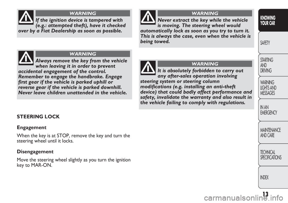
Never extract the key while the vehicle
is moving. The steering wheel would
automatically lock as soon as you try to turn it.
This is always the case, even when the vehicle is
being towed.
WARNING
It is absolutely forbidden to carry out
any after-sales operation involving
steering system or steering column
modifications (e.g. installing an anti-theft
device) that could badly affect performance and
safety, invalidate the warranty and also result in
the vehicle failing to comply with regulations.
WARNING
If the ignition device is tampered with
(e.g.: attempted theft), have it checked
over by a Fiat Dealership as soon as possible.
WARNING
Always remove the key from the vehicle
when leaving it in order to prevent
accidental engagement of the control.
Remember to engage the handbrake. Engage
first gear if the vehicle is parked uphill or
reverse gear if the vehicle is parked downhill.
Never leave children unattended in the vehicle.
WARNING
STEERING LOCK
Engagement
When the key is at STOP, remove the key and turn the
steering wheel until it locks.
Disengagement
Move the steering wheel slightly as you turn the ignition
key to MAR-ON.
Page 21 of 287
17
KNOWING
YOUR CAR
SAFETY
STARTING
AND
DRIVING
WARNING
LIGHTS AND
MESSAGES
IN AN
EMERGENCY
MAINTENANCE
AND CARE
TECHNICAL
SPECIFICATIONS
INDEX
If the needle reaches the red area, stop
the engine immediately and contact
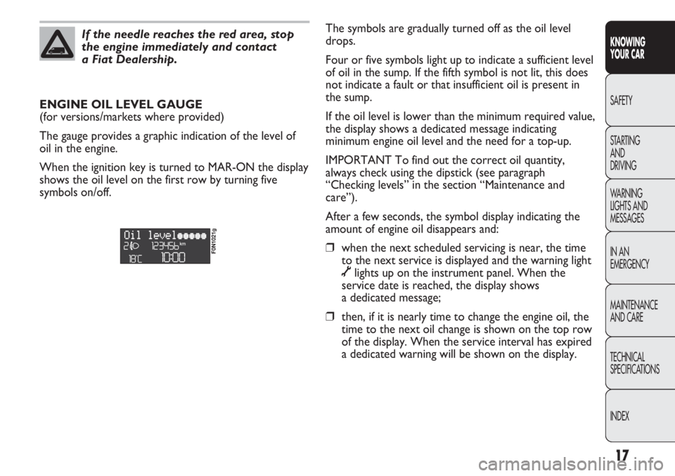
a Fiat Dealership.The symbols are gradually turned off as the oil level
drops.
Four or five symbols light up to indicate a sufficient level
of oil in the sump. If the fifth symbol is not lit, this does
not indicate a fault or that insufficient oil is present in
the sump.
If the oil level is lower than the minimum required value,
the display shows a dedicated message indicating
minimum engine oil level and the need for a top-up.
IMPORTANT To find out the correct oil quantity,
always check using the dipstick (see paragraph
“Checking levels” in the section “Maintenance and
care”).
After a few seconds, the symbol display indicating the
amount of engine oil disappears and:
❒when the next scheduled servicing is near, the time
to the next service is displayed and the warning light
õlights up on the instrument panel. When the
service date is reached, the display shows
a dedicated message;
❒then, if it is nearly time to change the engine oil, the
time to the next oil change is shown on the top row
of the display. When the service interval has expired
a dedicated warning will be shown on the display. ENGINE OIL LEVEL GAUGE
(for versions/markets where provided)
The gauge provides a graphic indication of the level of
oil in the engine.
When the ignition key is turned to MAR-ON the display
shows the oil level on the first row by turning five
symbols on/off.
F0N1021g
Page 31 of 287
27
KNOWING
YOUR CAR
SAFETY
STARTING
AND
DRIVING
WARNING
LIGHTS AND
MESSAGES
IN AN
EMERGENCY
MAINTENANCE
AND CARE
TECHNICAL
SPECIFICATIONS
INDEX
NOTE The “Scheduled Maintenance Plan” sets out
different service intervals depending on the engine type.
This indication will appear automatically with the key at
MAR-ONstarting from 2,000 km (or 1240 mi) and will
be presented automatically every 200 km (or 124 mi).
Oil change notification messages are displayed in the
same way. Use keys
▲and ▼to display service and oil
change due dates alternately. Below 200 km servicing
indications are more frequent. The display will be in
kilometres or miles depending on the measurement unit
settings. When the next scheduled service is
approaching, the message “Service” will appear on the
display followed by the number of kilometres or miles
left when the key is turned to
MAR-ON. Contact a Fiat
Dealership to carry out any service operation in the
“Scheduled servicing plan” and to reset the display. Scheduled Servicing (Service)
Using this function you can display information about
the mileage intervals for car servicing.
To consult this display, proceed as follows:
– briefly press button MODE: the display shows service
requirements in km or mi according to the previous
setting (see paragraph “Unit of measure”);
– briefly press button MODE to go back to the menu
screen or press the button for longer to go back to the
standard screen.
Page 33 of 287
29
KNOWING
YOUR CAR
SAFETY
STARTING
AND
DRIVING
WARNING
LIGHTS AND
MESSAGES
IN AN
EMERGENCY
MAINTENANCE
AND CARE
TECHNICAL
SPECIFICATIONS
INDEX
Values displayed
External temperature
Indicates the temperature outside the vehicle passenger
compartment.
Range (for versions/markets where provided)
It indicates the distance that can still be travelled based
on the fuel in the tank assuming that driving conditions
will not change. The message “---” will appear on the
display in the following cases:
– range value lower than 50 km (or 30 mi)
– vehicle left parked with engine running for long
period.
Trip distance
This value shows the distance covered from the start of
the new mission.
Average consumption (for versions/markets where provided)
This value shows the average consumption from the
start of the new mission.
Instant consumption (for versions/markets where provided)
This indicates instant fuel consumption and it is
constantly updated. The message “---” will appear on
the display if the vehicle is parked with the engine
running.
Average speed
Represents the average vehicle speed as a function of
the overall time elapsed since the start of a new mission.TRIP COMPUTER
General information
The “Trip computer” is used to display information on
vehicle operation when the key is turned to
MAR-ON.
This function allows you to define two separate trips,
called “Trip A” and “Trip B”, for monitoring the
vehicle’s “complete mission” (journey) in a reciprocally
independent manner. Both functions can be reset (reset
means start of a new journey).
“Trip A” is used to display the figures relating to:
– Outside temperature
– Range
– Trip distance
– Average consumption
– Current consumption
– Average speed
– Trip time (driving time).
“Trip B”, available on multifunction display only, is used
to display the figures relating to:
– Trip distance B
– Average consumption B
– Average speed B
– Trip time B (driving time).
NOTE “Trip B” function can be excluded (see paragraph
“Trip B on”). “Range” and “Instant consumption”
parameters cannot be reset.
Page 34 of 287
F0N0019mfig. 19
IMPORTANT If the reset operation is carried out when
“Trip B” is being displayed, only the information
associated with this function is reset.
Start of journey procedure
With the ignition key in the MAR-ON position, reset by
pressing the TRIP button and keeping it pressed for
more than 2 seconds.
Exit Trip
To quit the Trip function: keep button MODE pressed
for over 2 seconds. Trip time
This value shows the time elapsed since the start of the
new mission.
IMPORTANT In the absence of information, Trip
Computer values are displayed with “----”. When
normal operating conditions are restarted, calculation of
different units will restart regularly. The values displayed
before the failure will not be reset nor will a new
mission be started.
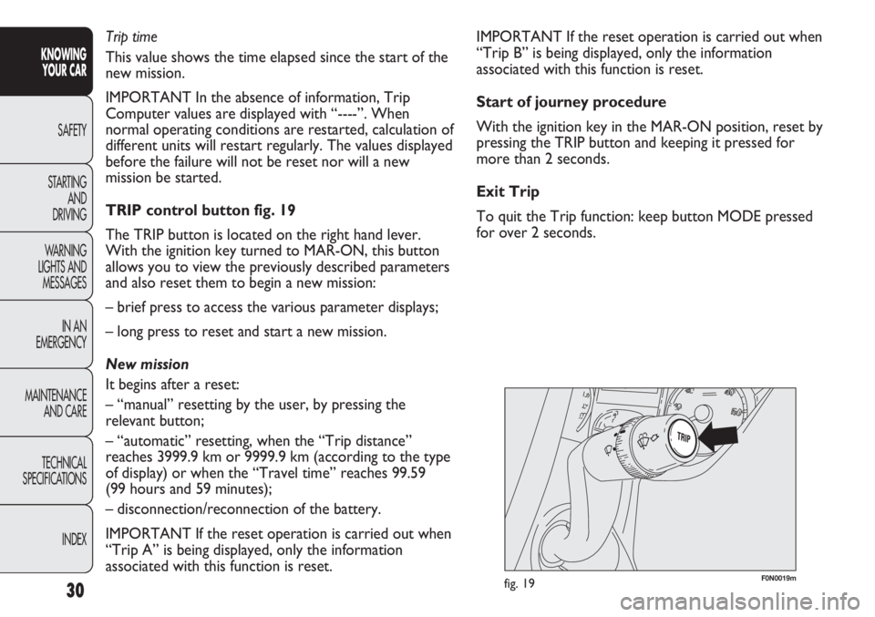
TRIP control button fig. 19
The TRIP button is located on the right hand lever.
With the ignition key turned to MAR-ON, this button
allows you to view the previously described parameters
and also reset them to begin a new mission:
– brief press to access the various parameter displays;
– long press to reset and start a new mission.
New mission
It begins after a reset:
– “manual” resetting by the user, by pressing the
relevant button;
– “automatic” resetting, when the “Trip distance”
reaches 3999.9 km or 9999.9 km (according to the type
of display) or when the “Travel time” reaches 99.59
(99 hours and 59 minutes);
– disconnection/reconnection of the battery.
IMPORTANT If the reset operation is carried out when
“Trip A” is being displayed, only the information
associated with this function is reset.
30
KNOWING
YOUR CAR
SAFETY
STARTING
AND
DRIVING
WARNING
LIGHTS AND
MESSAGES
IN AN
EMERGENCY
MAINTENANCE
AND CARE
TECHNICAL
SPECIFICATIONS
INDEX
Page 39 of 287
35
KNOWING
YOUR CAR
SAFETY
STARTING
AND
DRIVING
WARNING
LIGHTS AND
MESSAGES
IN AN
EMERGENCY
MAINTENANCE
AND CARE
TECHNICAL
SPECIFICATIONS
INDEX
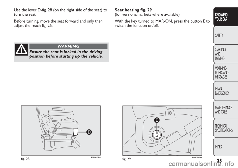
F0N0175mfig. 28F0N0213mfig. 29
Use the lever D-fig. 28 (on the right side of the seat) to
turn the seat.
Before turning, move the seat forward and only then
adjust the reach fig. 25.
Ensure the seat is locked in the driving
position before starting up the vehicle.
WARNING
Seat heating fig. 29
(for versions/markets where available)
With the key turned to MAR-ON, press the button E to
switch the function on/off.
Page 46 of 287
42
KNOWING
YOUR CAR
SAFETY
STARTING
AND
DRIVING
WARNING
LIGHTS AND
MESSAGES
IN AN
EMERGENCY
MAINTENANCE
AND CARE
TECHNICAL
SPECIFICATIONS
INDEX
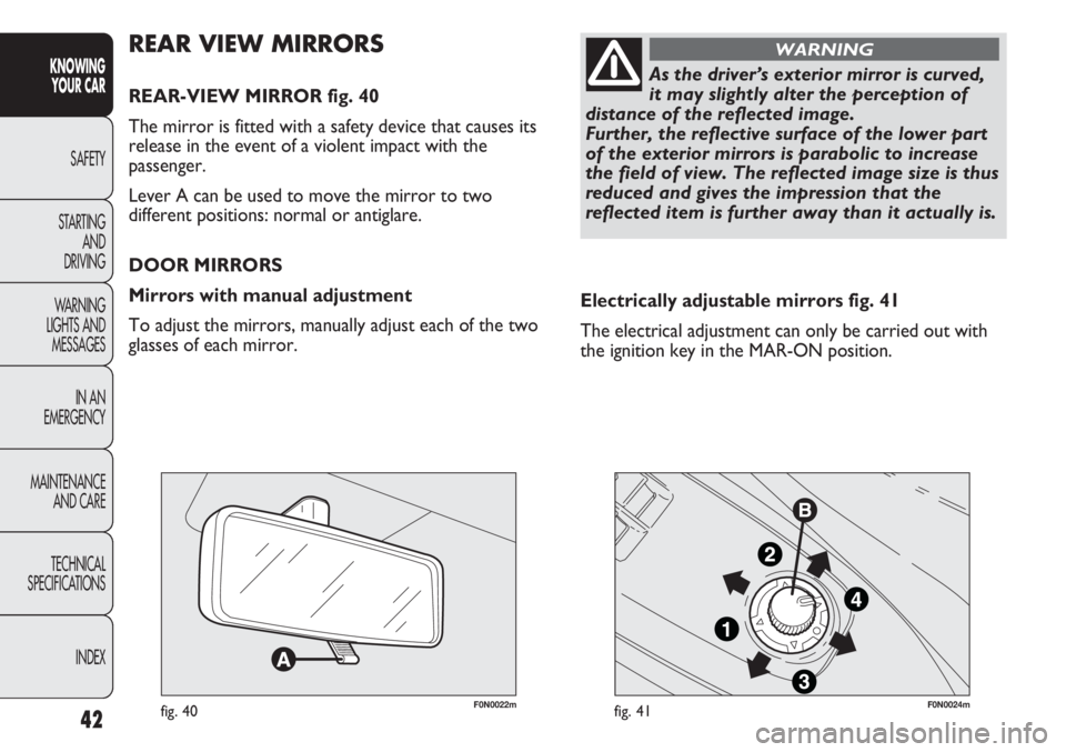
F0N0022mfig. 40F0N0024mfig. 41
Electrically adjustable mirrors fig. 41
The electrical adjustment can only be carried out with
the ignition key in the MAR-ON position.
REAR VIEW MIRRORS
REAR-VIEW MIRROR fig. 40
The mirror is fitted with a safety device that causes its
release in the event of a violent impact with the
passenger.
Lever A can be used to move the mirror to two
different positions: normal or antiglare.
DOOR MIRRORS
Mirrors with manual adjustment
To adjust the mirrors, manually adjust each of the two
glasses of each mirror.
As the driver’s exterior mirror is curved,
it may slightly alter the perception of
distance of the reflected image.
Further, the reflective surface of the lower part
of the exterior mirrors is parabolic to increase
the field of view. The reflected image size is thus
reduced and gives the impression that the
reflected item is further away than it actually is.
WARNING
Page 72 of 287
68
KNOWING
YOUR CAR
SAFETY
STARTING
AND
DRIVING
WARNING
LIGHTS AND
MESSAGES
IN AN
EMERGENCY
MAINTENANCE
AND CARE
TECHNICAL
SPECIFICATIONS
INDEX
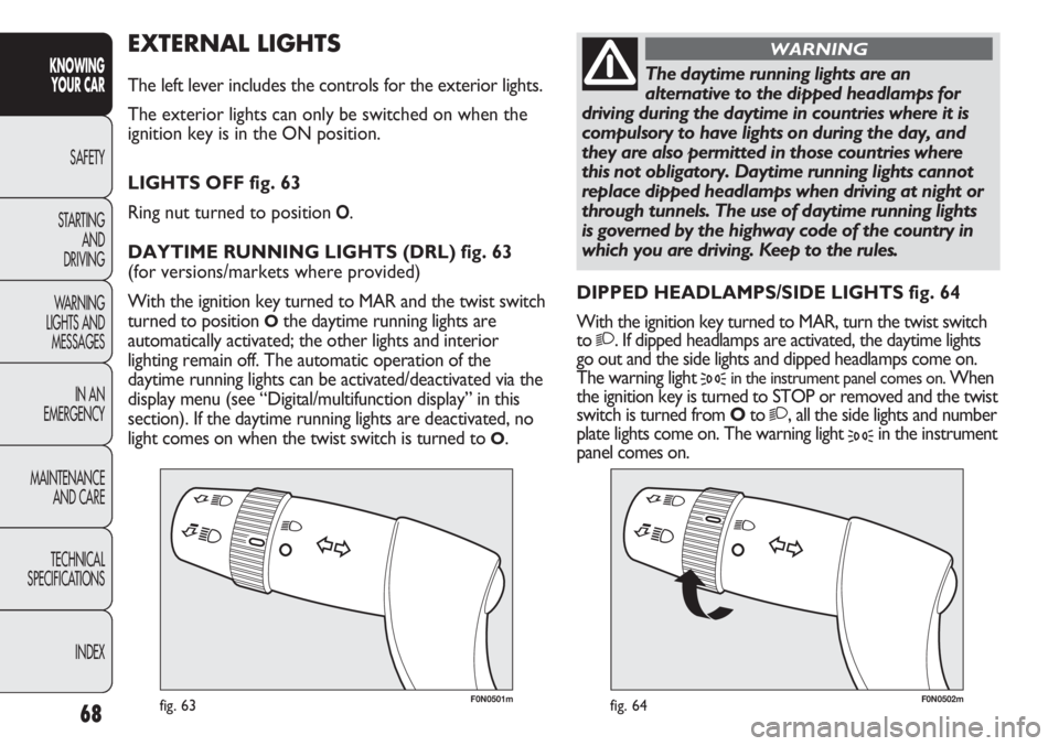
F0N0501mfig. 63F0N0502mfig. 64
EXTERNAL LIGHTS
The left lever includes the controls for the exterior lights.
The exterior lights can only be switched on when the
ignition key is in the ON position.
LIGHTS OFF fig. 63
Ring nut turned to position
O.
DAYTIME RUNNING LIGHTS (DRL) fig. 63
(for versions/markets where provided)
With the ignition key turned to MAR and the twist switch
turned to position
Othe daytime running lights are
automatically activated; the other lights and interior
lighting remain off. The automatic operation of the
daytime running lights can be activated/deactivated via the
display menu (see “Digital/multifunction display” in this
section). If the daytime running lights are deactivated, no
light comes on when the twist switch is turned to
O.DIPPED HEADLAMPS/SIDE LIGHTS fig. 64
With the ignition key turned to MAR, turn the twist switch
to
2. If dipped headlamps are activated, the daytime lights
go out and the side lights and dipped headlamps come on.
The warning light
3in the instrument panel comes on. When
the ignition key is turned to STOP or removed and the twist
switch is turned from Oto
2, all the side lights and number
plate lights come on. The warning light
3in the instrument
panel comes on.
The daytime running lights are an
alternative to the dipped headlamps for
driving during the daytime in countries where it is
compulsory to have lights on during the day, and
they are also permitted in those countries where
this not obligatory. Daytime running lights cannot
replace dipped headlamps when driving at night or
through tunnels. The use of daytime running lights
is governed by the highway code of the country in
which you are driving. Keep to the rules.
WARNING
Page 73 of 287
69
KNOWING
YOUR CAR
SAFETY
STARTING
AND
DRIVING
WARNING
LIGHTS AND
MESSAGES
IN AN
EMERGENCY
MAINTENANCE
AND CARE
TECHNICAL
SPECIFICATIONS
INDEX
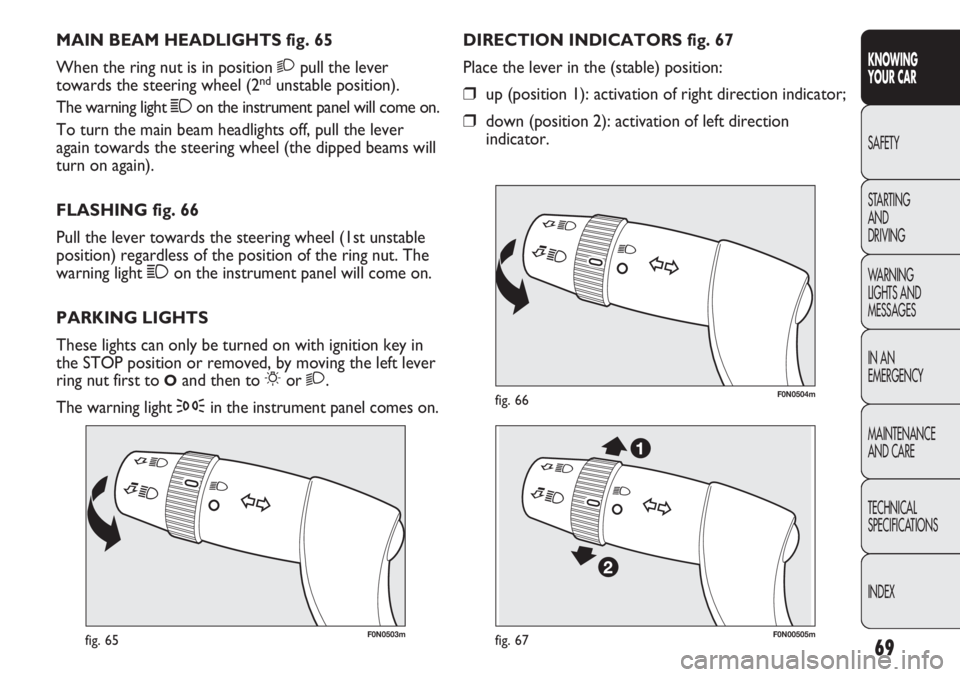
F0N0503mfig. 65
F0N0504mfig. 66
DIRECTION INDICATORS fig. 67
Place the lever in the (stable) position:
❒up (position 1): activation of right direction indicator;
❒down (position 2): activation of left direction
indicator. MAIN BEAM HEADLIGHTS fig. 65
When the ring nut is in position 2pull the lever
towards the steering wheel (2
ndunstable position).
The warning light 1on the instrument panel will come on.
To turn the main beam headlights off, pull the lever
again towards the steering wheel (the dipped beams will
turn on again).
FLASHING fig. 66
Pull the lever towards the steering wheel (1st unstable
position) regardless of the position of the ring nut. The
warning light 1on the instrument panel will come on.
PARKING LIGHTS
These lights can only be turned on with ignition key in
the STOP position or removed, by moving the left lever
ring nut first to
Oand then to 6or 2.
The warning light
3in the instrument panel comes on.
F0N00505mfig. 67
Page 74 of 287
70
KNOWING
YOUR CAR
SAFETY
STARTING
AND
DRIVING
WARNING
LIGHTS AND
MESSAGES
IN AN
EMERGENCY
MAINTENANCE
AND CARE
TECHNICAL
SPECIFICATIONS
INDEX
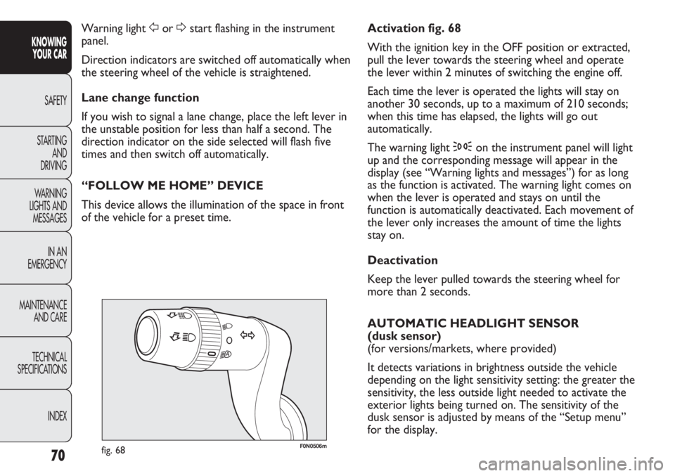
F0N0506mfig. 68
Activation fig. 68
With the ignition key in the OFF position or extracted,
pull the lever towards the steering wheel and operate
the lever within 2 minutes of switching the engine off.
Each time the lever is operated the lights will stay on
another 30 seconds, up to a maximum of 210 seconds;
when this time has elapsed, the lights will go out
automatically.
The warning light 3on the instrument panel will light
up and the corresponding message will appear in the
display (see “Warning lights and messages”) for as long
as the function is activated. The warning light comes on
when the lever is operated and stays on until the
function is automatically deactivated. Each movement of
the lever only increases the amount of time the lights
stay on.
Deactivation
Keep the lever pulled towards the steering wheel for
more than 2 seconds.
AUTOMATIC HEADLIGHT SENSOR
(dusk sensor)
(for versions/markets, where provided)
It detects variations in brightness outside the vehicle
depending on the light sensitivity setting: the greater the
sensitivity, the less outside light needed to activate the
exterior lights being turned on. The sensitivity of the
dusk sensor is adjusted by means of the “Setup menu”
for the display. Warning light For Dstart flashing in the instrument
panel.
Direction indicators are switched off automatically when
the steering wheel of the vehicle is straightened.
Lane change function
If you wish to signal a lane change, place the left lever in
the unstable position for less than half a second. The
direction indicator on the side selected will flash five
times and then switch off automatically.
“FOLLOW ME HOME” DEVICE
This device allows the illumination of the space in front
of the vehicle for a preset time.