engine FIAT DUCATO 2011 Owner handbook (in English)
[x] Cancel search | Manufacturer: FIAT, Model Year: 2011, Model line: DUCATO, Model: FIAT DUCATO 2011Pages: 287, PDF Size: 4.42 MB
Page 71 of 287
67
KNOWING
YOUR CAR
SAFETY
STARTING
AND
DRIVING
WARNING
LIGHTS AND
MESSAGES
IN AN
EMERGENCY
MAINTENANCE
AND CARE
TECHNICAL
SPECIFICATIONS
INDEX
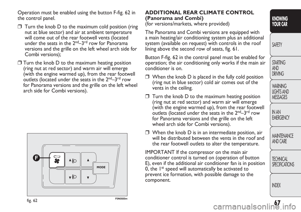
Operation must be enabled using the button F-fig. 62 in
the control panel.
❒Turn the knob D to the maximum cold position (ring
nut at blue sector) and air at ambient temperature
will come out of the rear footwell vents (located
under the seats in the 2
nd–3rdrow for Panorama
versions and the grille on the left wheel arch side for
Combi versions);
❒Turn the knob D to the maximum heating position
(ring nut at red sector) and warm air will emerge
(with the engine warmed up), from the rear footwell
outlets (located under the seats in the 2
nd–3rdrow
for Panorama versions and the grille on the left wheel
arch side for Combi versions).
F0N0500mfig. 62
ADDITIONAL REAR CLIMATE CONTROL
(Panorama and Combi)
(for versions/markets, where provided)
The Panorama and Combi versions are equipped with
a main heating/air conditioning system plus an additional
system (available on request) with controls in the roof
lining above the second row of seats, fig. 61.
Button F-fig. 62 in the control panel must be enabled for
operation; the air conditioning only works if the main air
conditioner is on.
❒When the knob D is placed in the fully cold position
(ring nut in blue sector) cold air comes out of the
vents in the ceiling.
❒Turn the knob D to the maximum heating position
(ring nut at red sector) and warm air will emerge
(with the engine warmed up), from the rear footwell
outlets (located under the seats in the 2
nd–3rdrow
for Panorama versions and the grille on the left
wheel arch side for Combi versions).
❒When the knob D is in an intermediate position, air
will be distributed between the vents in the roof and
the rear footwell outlets to alter the temperature.
IMPORTANT If the compressor on the main air
conditioner control is turned on (operation of button
E), even if the additional air conditioner fan is in position
0, the 1
stspeed will automatically be activated to
prevent ice formation, with possible damage to the
component.
Page 74 of 287
70
KNOWING
YOUR CAR
SAFETY
STARTING
AND
DRIVING
WARNING
LIGHTS AND
MESSAGES
IN AN
EMERGENCY
MAINTENANCE
AND CARE
TECHNICAL
SPECIFICATIONS
INDEX
F0N0506mfig. 68
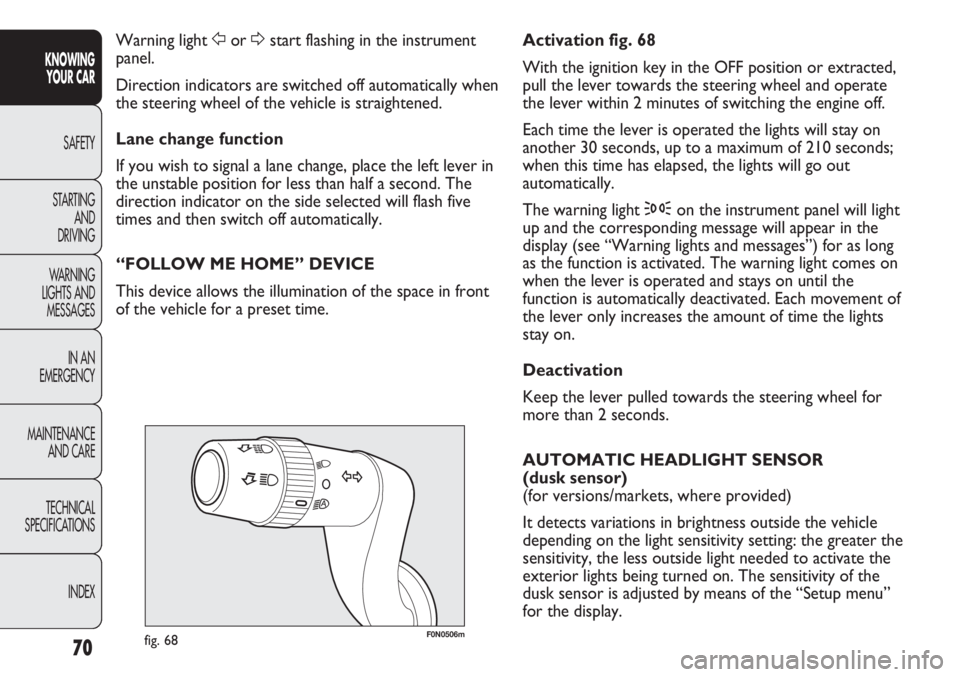
Activation fig. 68
With the ignition key in the OFF position or extracted,
pull the lever towards the steering wheel and operate
the lever within 2 minutes of switching the engine off.
Each time the lever is operated the lights will stay on
another 30 seconds, up to a maximum of 210 seconds;
when this time has elapsed, the lights will go out
automatically.
The warning light 3on the instrument panel will light
up and the corresponding message will appear in the
display (see “Warning lights and messages”) for as long
as the function is activated. The warning light comes on
when the lever is operated and stays on until the
function is automatically deactivated. Each movement of
the lever only increases the amount of time the lights
stay on.
Deactivation
Keep the lever pulled towards the steering wheel for
more than 2 seconds.
AUTOMATIC HEADLIGHT SENSOR
(dusk sensor)
(for versions/markets, where provided)
It detects variations in brightness outside the vehicle
depending on the light sensitivity setting: the greater the
sensitivity, the less outside light needed to activate the
exterior lights being turned on. The sensitivity of the
dusk sensor is adjusted by means of the “Setup menu”
for the display. Warning light For Dstart flashing in the instrument
panel.
Direction indicators are switched off automatically when
the steering wheel of the vehicle is straightened.
Lane change function
If you wish to signal a lane change, place the left lever in
the unstable position for less than half a second. The
direction indicator on the side selected will flash five
times and then switch off automatically.
“FOLLOW ME HOME” DEVICE
This device allows the illumination of the space in front
of the vehicle for a preset time.
Page 79 of 287
75
KNOWING
YOUR CAR
SAFETY
STARTING
AND
DRIVING
WARNING
LIGHTS AND
MESSAGES
IN AN
EMERGENCY
MAINTENANCE
AND CARE
TECHNICAL
SPECIFICATIONS
INDEX
INCREASING THE MEMORISED SPEED
This can be done in two ways:
❒by pressing the accelerator and then memorising the
new speed reached;
or
❒by moving the lever upwards (+).
Each operation of the lever will correspond to a slight
increase in speed of about 1 km/h, while keeping the
lever upwards will correspond to a continuous speed
increase.
REDUCING THE MEMORISED SPEED
This can be done in two ways:
❒by turning the device off and then storing a new
speed;
or
❒by moving the stalk downwards (–) until reaching the
new speed which will be memorised automatically.
Each movement of the lever will correspond to a slight
reduction in speed of about 1 km/h, while keeping the
lever held downwards will correspond to a continuous
speed reduction.SWITCHING THE DEVICE OFF
The device can be switched off by the driver in the
following ways:
❒turning the ring nut A to the OFFposition;
❒turning the engine off;
❒pressing the brake pedal or operating the handbrake;
❒pressing the clutch pedal;
❒requesting a gear change with an automatic gearbox
in sequential mode;
❒with vehicle speed below the set limit;
❒by pressing the accelerator pedal; in this case the
system is not really switched off but the request for
acceleration takes priority over the system. The
cruise control is, however, active and it will not be
necessary to press the RES button to restore the
previous conditions after the acceleration is over.
The device is automatically switched off in the following
cases:
❒if the ABSor ESPsystems cut in;
❒if there is a system failure.
Page 81 of 287
77
KNOWING
YOUR CAR
SAFETY
STARTING
AND
DRIVING
WARNING
LIGHTS AND
MESSAGES
IN AN
EMERGENCY
MAINTENANCE
AND CARE
TECHNICAL
SPECIFICATIONS
INDEX
❒when opening one of the side doors for about
3 minutes;
❒when one of the doors is closed for a period of
about 10 seconds.
The timed delay period ends automatically when the
doors are locked.
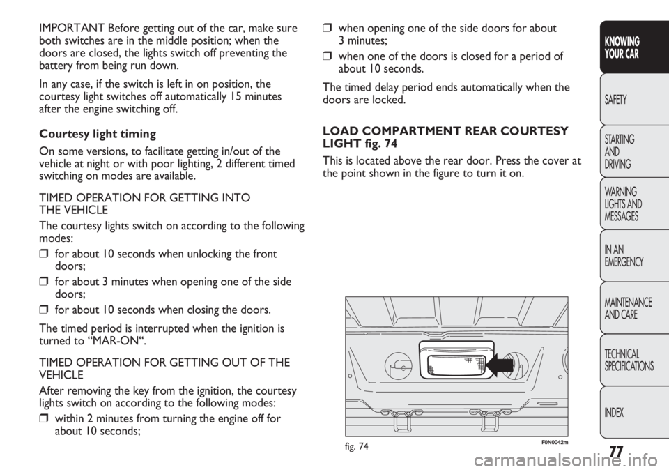
LOAD COMPARTMENT REAR COURTESY
LIGHT fig. 74
This is located above the rear door. Press the cover at
the point shown in the figure to turn it on. IMPORTANT Before getting out of the car, make sure
both switches are in the middle position; when the
doors are closed, the lights switch off preventing the
battery from being run down.
In any case, if the switch is left in on position, the
courtesy light switches off automatically 15 minutes
after the engine switching off.
Courtesy light timing
On some versions, to facilitate getting in/out of the
vehicle at night or with poor lighting, 2 different timed
switching on modes are available.
TIMED OPERATION FOR GETTING INTO
THE VEHICLE
The courtesy lights switch on according to the following
modes:
❒for about 10 seconds when unlocking the front
doors;
❒for about 3 minutes when opening one of the side
doors;
❒for about 10 seconds when closing the doors.
The timed period is interrupted when the ignition is
turned to “MAR-ON“.
TIMED OPERATION FOR GETTING OUT OF THE
VEHICLE
After removing the key from the ignition, the courtesy
lights switch on according to the following modes:
❒within 2 minutes from turning the engine off for
about 10 seconds;
F0N0042mfig. 74
Page 86 of 287
82
KNOWING
YOUR CAR
SAFETY
STARTING
AND
DRIVING
WARNING
LIGHTS AND
MESSAGES
IN AN
EMERGENCY
MAINTENANCE
AND CARE
TECHNICAL
SPECIFICATIONS
INDEX
F0N0048mfig. 85
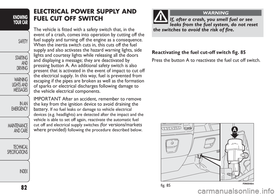
ELECTRICAL POWER SUPPLY AND
FUEL CUT OFF SWITCH
The vehicle is fitted with a safety switch that, in the
event of a crash, comes into operation by cutting off the
fuel supply and turning off the engine as a consequence.
When the inertia switch cuts in, this cuts off the fuel
supply and also activates the hazard warning lights, side
lights and courtesy lights while releasing all the doors
and displaying a message; they are deactivated by
pressing button A. An additional safety switch is also
present that is activated in the event of impact to cut off
the electrical supply. In this way, fuel is prevented from
escaping if the pipes are broken as well as the formation
of sparks or electrical discharges following damage to
the vehicle electrical components.
IMPORTANT After an accident, remember to remove
the key from the ignition device to avoid draining the
battery.
If no fuel leaks or damage to vehicle electrical
devices (e.g. headlights) are detected after the impact and the
vehicle is able to set off again, reactivate the automatic fuel
cut off and electrical supply switches (
for versions/markets
where provided)
following the procedure described below.
If, after a crash, you smell fuel or see
leaks from the fuel system, do not reset
the switches to avoid the risk of fire.
WARNING
Reactivating the fuel cut-off switch fig. 85
Press the button A to reactivate the fuel cut off switch.
Page 109 of 287
105
KNOWING
YOUR CAR
SAFETY
STARTING
AND
DRIVING
WARNING
LIGHTS AND
MESSAGES
IN AN
EMERGENCY
MAINTENANCE
AND CARE
TECHNICAL
SPECIFICATIONS
INDEX
F0N0323mfig. 124F0N0065mfig. 125
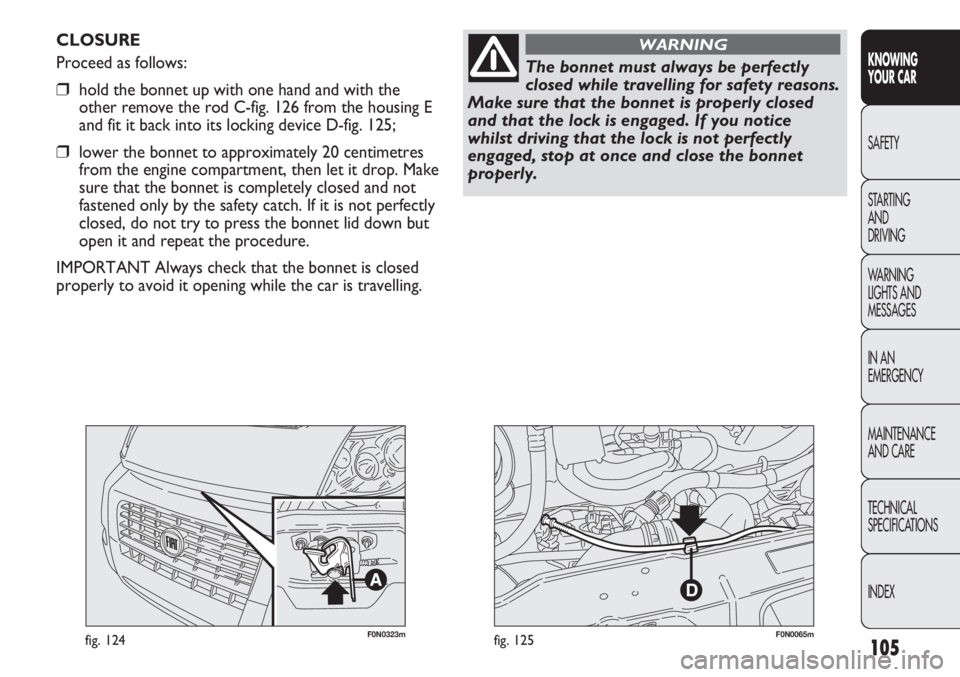
CLOSURE
Proceed as follows:
❒hold the bonnet up with one hand and with the
other remove the rod C-fig. 126 from the housing E
and fit it back into its locking device D-fig. 125;
❒lower the bonnet to approximately 20 centimetres
from the engine compartment, then let it drop. Make
sure that the bonnet is completely closed and not
fastened only by the safety catch. If it is not perfectly
closed, do not try to press the bonnet lid down but
open it and repeat the procedure.
IMPORTANT Always check that the bonnet is closed
properly to avoid it opening while the car is travelling.
The bonnet must always be perfectly
closed while travelling for safety reasons.
Make sure that the bonnet is properly closed
and that the lock is engaged. If you notice
whilst driving that the lock is not perfectly
engaged, stop at once and close the bonnet
properly.
WARNING
Page 114 of 287
110
KNOWING
YOUR CAR
SAFETY
STARTING
AND
DRIVING
WARNING
LIGHTS AND
MESSAGES
IN AN
EMERGENCY
MAINTENANCE
AND CARE
TECHNICAL
SPECIFICATIONS
INDEX
ESP SYSTEM
(Electronic Stability Program)
(for versions/markets where provided)
This is an electronic system that controls vehicle
stability in the event of tyre grip loss, helping to maintain
directional control.
The ESP system is therefore particularly useful when
grip conditions of road surfaces change.
The MSR system (adjustment of the engine braking
torque during gear changes) and the HBA system
(automatic increase in the braking pressure during
emergency braking) are present with ESP, ASR and Hill
Holder systems (for versions/markets where provided).
SYSTEM INTERVENTION
This is signalled by the flashing of warning light
áin the
instrument panel, to inform the driver that the vehicle is
in critical stability and grip conditions.
SYSTEM ACTIVATION
The ESP system is automatically activated when the
vehicle is started and cannot be de-activated. BRAKE ASSIST (emergency braking assistance
integrated in ESP)
(for versions/markets where provided)
This system (which cannot be deactivated) recognises
emergency braking conditions according to the speed of
operation of the brake pedal and provides an additional
hydraulic braking pressure to support that provided by
the driver. This allows faster and more powerful
operation of the braking system.
The Brake Assist is deactivated on versions equipped
with ESP, in the event of an ESP system failure (indicated
by warning light
áswitching on together with the
message in the multifunction display, for
versions/markets where provided).
When the ABS intervenes and you notice
the brake pedal pulsating, do not be
afraid to keep the pedal pushed down. This will
help you to stop in the shortest distance
possible, depending on the road conditions.
WARNING
Page 115 of 287
111
KNOWING
YOUR CAR
SAFETY
STARTING
AND
DRIVING
WARNING
LIGHTS AND
MESSAGES
IN AN
EMERGENCY
MAINTENANCE
AND CARE
TECHNICAL
SPECIFICATIONS
INDEX
❒downhill: vehicle stationary on a road with a gradient
higher than 5%, engine running, clutch and brake
pedal pressed and reverse gear engaged.
At pickup the
ESPsystem control unit will maintain the
braking pressure at the wheels until the necessary torque
for starting is reached or, in any case, for a maximum of
2 seconds in order to move easily from the brake pedal
to the accelerator pedal. When two seconds have
elapsed, without starting, the system is automatically
deactivated, gradually releasing the braking pressure.
During this release stage, the typical brake
disengagement noise indicating that the vehicle is going
to move imminently will be heard.
Failure warning
The
áwarning light in the instrument panel will come
on in the event of a failure (see “Warning lights and
messages” section).
IMPORTANT The Hill Holder system is not a parking
brake; therefore, never leave the vehicle without having
engaged the handbrake, turned the engine off and
engaged first gear. FAILURE WARNING
In the event of a failure, the ESP will be automatically
switched off and the áwarning light will come on
constantly in the instrument panel along with a message
in the multifunction display (for versions/markets where
provided) (see “Warning lights and messages” section).
The LED in the ASR OFF button will light up. Contact
a Fiat Dealership as soon as possible if this happens.
Do not take unnecessary risks, even if
your vehicle is fitted with an ESP system.
Your driving style must always be suited to the
road conditions, visibility and traffic. The driver
is ultimately responsible for road safety.
WARNING
HILL HOLDER SYSTEM
This system is an integral part of the
ESPsystem and it is
provided to facilitate starting on hills.
It is automatically activated in the following conditions:
❒uphill: vehicle stationary on a road with a gradient
higher than 5%, engine running, clutch and brake
pedal pressed, gearbox in neutral or gear other than
reverse engaged;
For the correct operation of the ESP and
ASR systems, the tyres must absolutely be
the same make and type on all wheels, in perfect
condition and, above all, of the type, make and
size specified.
WARNING
Page 116 of 287
112
KNOWING
YOUR CAR
SAFETY
STARTING
AND
DRIVING
WARNING
LIGHTS AND
MESSAGES
IN AN
EMERGENCY
MAINTENANCE
AND CARE
TECHNICAL
SPECIFICATIONS
INDEX
MSR system
(engine braking torque control)
This is an integral part of the ASR system that, in the
event of a sudden gear down shift, cuts in and provides
torque to the engine thus preventing excessive drive
wheel drive which, especially in poor grip conditions,
can lead to a loss of stability. ASR SYSTEM (Antislip Regulator)
This is a traction control system that cuts in
automatically every time one or both drive wheels slip.
Depending on the slipping conditions, two different
control systems are activated:
❒if the slipping involves both drive wheels, the ASR
function intervenes by reducing the power
transmitted by the engine;
❒if the slipping only involves only one driving wheel,
the ASR system cuts in by automatically braking the
wheel that is slipping.
The action of the
ASRis particularly helpful in the
following circumstances:
❒slipping of the inner wheel when cornering due to
the effect of dynamic load changes or excessive
acceleration;
❒too much power transmitted to the wheels also in
relation to the conditions of the road surface;
❒acceleration on slippery, snowy or icy surfaces;
❒loss of grip on a wet surface (aquaplaning).
For the correct operation of the ESP and
ASR systems, the tyres must absolutely be
the same make and type on all wheels, in perfect
condition and, above all, of the type, make and
size specified.
WARNING
Page 117 of 287
113
KNOWING
YOUR CAR
SAFETY
STARTING
AND
DRIVING
WARNING
LIGHTS AND
MESSAGES
IN AN
EMERGENCY
MAINTENANCE
AND CARE
TECHNICAL
SPECIFICATIONS
INDEX
FAILURE WARNING
In the event of a failure, the ASR will be automatically
switched off and the áwarning light will come on
constantly in the instrument panel along with a message
in the multifunction display (for versions/markets where
provided) (see “Warning lights and messages” section).
The LED in the ASR OFF button will light up. Contact
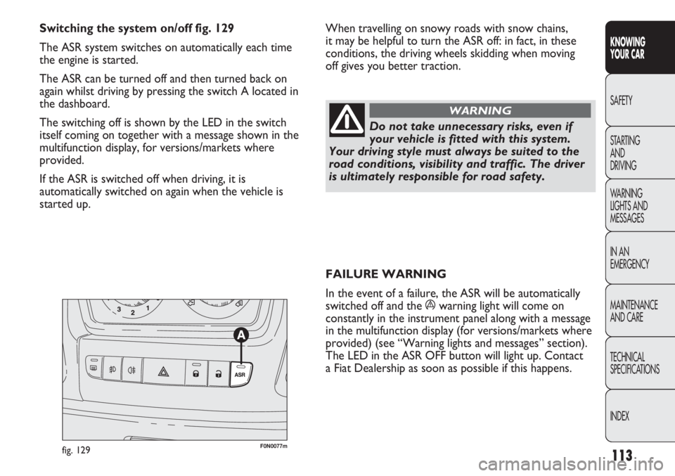
a Fiat Dealership as soon as possible if this happens. Switching the system on/off fig. 129
The ASR system switches on automatically each time
the engine is started.
The ASR can be turned off and then turned back on
again whilst driving by pressing the switch A located in
the dashboard.
The switching off is shown by the LED in the switch
itself coming on together with a message shown in the
multifunction display, for versions/markets where
provided.
If the ASR is switched off when driving, it is
automatically switched on again when the vehicle is
started up.
F0N0077mfig. 129
Do not take unnecessary risks, even if
your vehicle is fitted with this system.
Your driving style must always be suited to the
road conditions, visibility and traffic. The driver
is ultimately responsible for road safety.
WARNING
When travelling on snowy roads with snow chains,
it may be helpful to turn the ASR off: in fact, in these
conditions, the driving wheels skidding when moving
off gives you better traction.