brake FIAT DUCATO 2015 3.G Owners Manual
[x] Cancel search | Manufacturer: FIAT, Model Year: 2015, Model line: DUCATO, Model: FIAT DUCATO 2015 3.GPages: 387, PDF Size: 20.76 MB
Page 6 of 387
READ THIS CAREFULLY
REFUELLING
Only refuel with automotive diesel conforming to the European specification EN590. The use of other products or mixtures may damage the
engine beyond repair and consequently invalidate the warranty, due to the damage caused.
STARTING THE ENGINE
Make sure that the handbrake is engaged; set the gear lever to neutral; fully depress the clutch pedal without pressing the accelerator, then
turn the ignition key to MAR-ON and wait for the warning lightsandto switch off; turn the ignition key to AVV and release it as
soon as the engine has started.
PARKING ON FLAMMABLE MATERIAL
The catalytic converter develops high temperatures during operation. Do not park on grass, dry leaves, pine needles or other flammable
material: fire hazard.
RESPECTING THE ENVIRONMENT
The vehicle is fitted with a system that allows continuous diagnosis of the emission-related components in order to help protect the
environment.
ELECTRICAL ACCESSORIES
If, after buying the vehicle, you decide to add electrical accessories (with the risk of gradually draining the battery), visit a Fiat Dealership. They
can calculate the overall electrical requirement and check that the vehicle's electrical system can support the required load.
SCHEDULED SERVICING
Correct maintenance enables the vehicle to perfectly maintain performance and safety characteristics, its environmental friendliness and low
running costs over time.
THE OWNER HANDBOOK CONTAINS
... important information, advice and warnings for correct use, driving safety and maintenance of your vehicle over time. Special attention
must be paid to the symbols(safety of persons)(environmental protection)(vehicle integrity).
Page 10 of 387
.
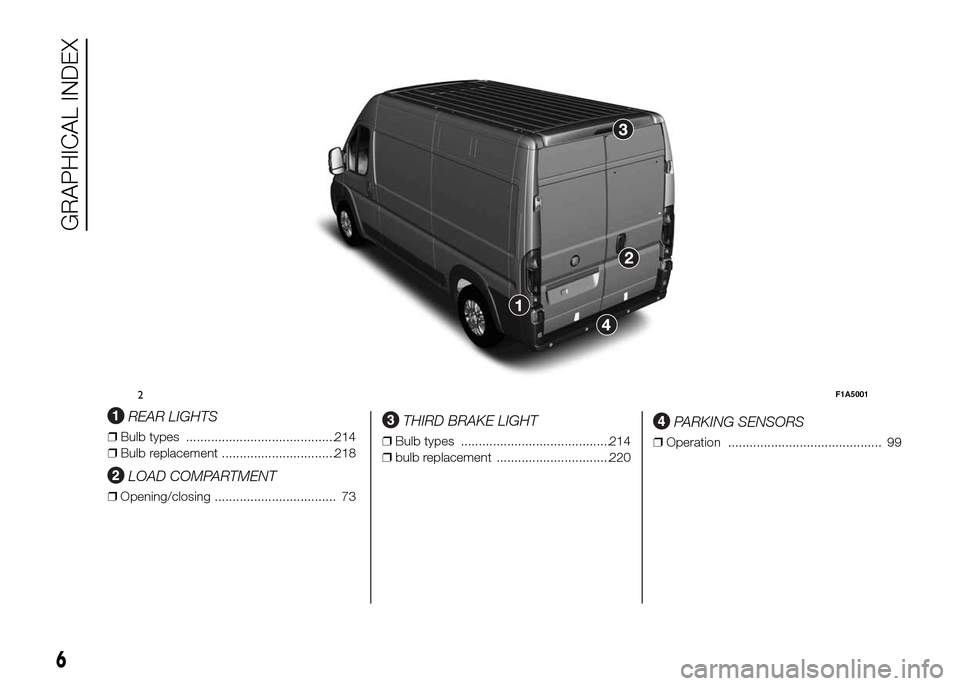
REAR LIGHTS
❒Bulb types ..........................................214
❒Bulb replacement ................................218
LOAD COMPARTMENT
❒Opening/closing .................................. 73
THIRD BRAKE LIGHT
❒Bulb types ..........................................214
❒bulb replacement ................................220
PARKING SENSORS
❒Operation ........................................... 99
2F1A5001
6
GRAPHICAL INDEX
Page 12 of 387
.
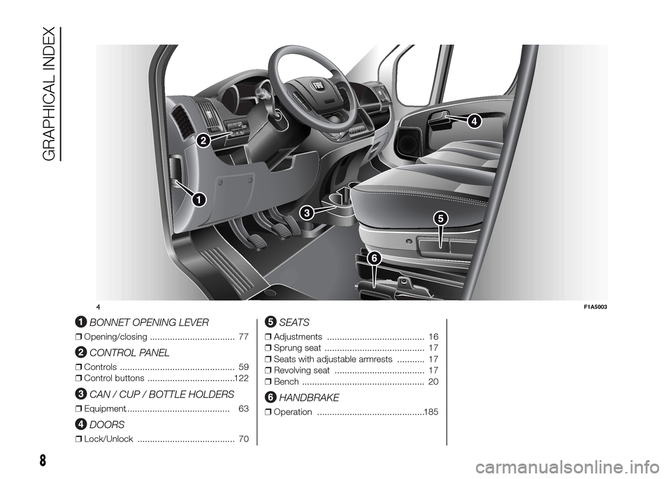
BONNET OPENING LEVER
❒Opening/closing .................................. 77
CONTROL PANEL
❒Controls .............................................. 59
❒Control buttons ...................................122
CAN / CUP / BOTTLE HOLDERS
❒Equipment.......................................... 63
DOORS
❒Lock/Unlock ....................................... 70
SEATS
❒Adjustments ....................................... 16
❒Sprung seat ........................................ 17
❒Seats with adjustable armrests ........... 17
❒Revolving seat .................................... 17
❒Bench ................................................. 20
HANDBRAKE
❒Operation ...........................................185
MO
DE
4F1A5003
8
GRAPHICAL INDEX
Page 20 of 387
STEERING LOCK
Activation
When the key is at STOP, remove the
key and turn the steering wheel until
it locks.
Disengagement
Move the steering wheel slightly as you
turn the ignition key to MAR-ON
WARNING
2) If the ignition device has been
tampered with (e.g. an attempted
theft), have it checked over by a
Fiat Dealership before driving
again.
3) Always remove the key when you
leave your vehicle to prevent
someone from accidentally
operating the controls. Remember
to engage the handbrake.
Engage first gear if the vehicle is
parked uphill or reverse gear if the
vehicle is parked downhill. Never
leave children unattended in the
vehicle.4) Never extract the key while the
vehicle is moving. The steering
wheel will lock as soon as it is
turned. This also applies to cases
in which the vehicle is towed.
5) Under no circumstances should
aftermarket operations be carried
out involving steering system or
steering column modifications
(e.g. installation of anti-theft
device). This could negatively
affect performance and safety,
invalidate the warranty, cause
serious safety problems and also
result in vehicle non-compliance
with type-approval requirements.
SEATS
6)
2)
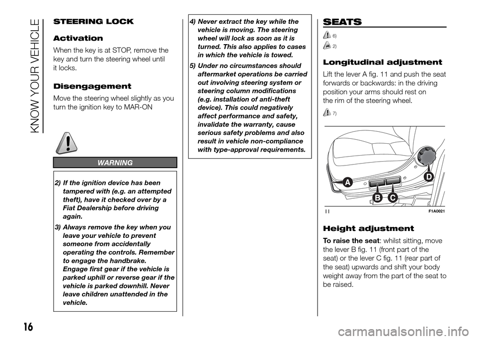
Longitudinal adjustment
Lift the lever A fig. 11 and push the seat
forwards or backwards: in the driving
position your arms should rest on
the rim of the steering wheel.
7)
Height adjustment
To raise the seat: whilst sitting, move
the lever B fig. 11 (front part of the
seat) or the lever C fig. 11 (rear part of
the seat) upwards and shift your body
weight away from the part of the seat to
be raised.
11F1A0021
16
KNOW YOUR VEHICLE
Page 27 of 387
The seat can be turned 180º toward
the seat on the opposite side. To turn it,
see the "Seat with revolving base"
paragraph.
4-SEATER BENCH SEAT
(Crew Cab Van versions)
(for versions/markets, where provided)
For specific versions, the vehicle
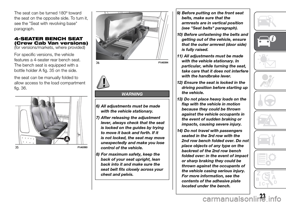
features a 4-seater rear bench seat.
The bench seat is equipped with a
bottle holder A fig. 35 on the side.
the seat can be manually folded to
allow access to the load compartment
fig. 36.
WARNING
6) All adjustments must be made
with the vehicle stationary.
7) After releasing the adjustment
lever, always check that the seat
is locked on the guides by trying
to move it back and forth. If it
is not locked, the seat may move
unexpectedly and make you lose
control of the vehicle.
8) For maximum safety, keep the
back of your seat upright, lean
back into it and make sure the
seat belt fits closely across your
chest and pelvis.9) Before putting on the front seat
belts, make sure that the
armrests are in vertical position
(see "Seat belts" paragraph).
10) Before unfastening the belts and
getting out of the vehicle, ensure
that the outer armrest (door side)
is fully raised.
11) All adjustments must be made
with the vehicle stationary. In
particular, while turning the seat,
take care that it does not interfere
with the handbrake lever.
12) Ensure the seat is locked in the
driving position before starting up
the vehicle.
13) Do not place heavy loads on the
flap with the vehicle in motion
because they could be thrown
against the vehicle occupants in
the event of sudden braking or
impacts, causing severe injury.
14) Do not travel with passengers
seated in the 3rd row with the
2nd row bench folded over. Do not
place objects of any type on the
backrest of the 2nd row bench
folded over: in the event of impact
or sharp braking they could be
thrown against the occupants of
the vehicle casing serious injury.
For more information, see the
contents of the adhesive plate
located under the bench.
35F1A0393
36F1A0394
23
Page 59 of 387
Storing vehicle speed
Proceed as follows:
❒turn ring nut A fig. 66 - fig. 67 to ON
or
(according to the version) and
press the accelerator pedal so that
the vehicle reaches the desired
speed;
❒move the stalk upwards (+) for at
least one second, then release it. The
vehicle speed is now stored and
you can therefore release the
accelerator pedal.
If necessary (e.g. when overtaking)
acceleration is possible by simply
pressing the accelerator pedal:
releasing the accelerator pedal the car
will return to the speed stored
previously.
Restoring the stored
speed
If the device has been deactivated, for
example by depressing the brake or
clutch pedal, the stored speed can be
restored as follows:
❒accelerate progressively until a speed
close to that stored is reached;
❒engage the gear selected at the time
that the speed was stored;
❒press button B fig. 66 - fig. 67.Increasing the stored
speed
This can be done in two ways:
❒by pressing the accelerator and
storing the new speed reached
or
❒by moving the stalk upwards (+).
Each activation of the lever
corresponds to an increase in speed of
about 1 km/h, whilst keeping the lever
upwards varies the speed continuously.
Reducing the stored
speed
This can be done in two ways:
❒by switching off the device and then
storing the new speed;
or
❒by moving the stalk downwards (-)
until the new speed, which will be
stored automatically, is reached.
Each movement of the lever will
correspond to a slight reduction in
speed of about 1 km/h, while keeping
the lever held downwards will decrease
the speed continuously.Deactivating the device
The device can be switched off by
the driver in the following ways:
❒turning ring nut A to OFF orO
(according to the version);
❒by stopping the engine;
Deactivating the
function
The device can be switched off by the
driver in the following ways:
❒turning ring nut A to OFF orO
(according to the version);
❒pressing the button B, both with
symbolIIand symbol CANC/RES,
the system pauses;
❒by stopping the engine;
❒by pressing the brake pedal or
operating the handbrake;
❒by pressing the clutch pedal;
❒requesting a gear shift with an
automatic transmission in sequential
mode;
❒with the vehicle speed below the set
limit
55
Page 85 of 387
ABS
This is an integral part of the braking
system, which prevents one or more
wheels from locking or slipping
regardless of the road surface
conditions and braking intensity,
ensuring control of the vehicle even
during emergency braking.
The system intervenes when braking
and the wheels are about to lock,
typically in emergency braking or
low-grip conditions, when locking may
be more frequent.
The ABS ensures the direction of the
vehicle while braking and optimises the
braking distances at the same time.
The system also improves control and
stability of the car when braking on a
surface where the grip of the left and
right wheels varies, or when braking on
corners.
The system is completed by EBD
(Electronic Braking Force Distribution),
which distributes the braking action
between the front and rear wheels.
IMPORTANT To obtain the maximum
efficiency of the braking system, a
bedding-in period of about 500 km is
needed: during this period it is better to
avoid sharp, repeated and prolonged
braking.
50)
SYSTEM INTERVENTION
The driver can feel that the ABS has
come into action because the brake
pedal pulsates slightly and the system
gets noisier: it means that the car
speed should be altered to suit the type
of road surface.
51) 52) 52) 53) 54) 55) 56) 57)
MSR SYSTEM
(Motor Schleppmoment Regelung)
This system is an integral part of the
ABS and intervenes, if there is sudden
downshifting, restoring torque to the
engine, thereby preventing excessive
drive at the drive wheels which,
especially in poor grip conditions, could
lead to a loss in stability of the vehicle.
WARNING
50) The ABS exploits the grip
available to the full, but it cannot
improve it. Therefore, you should
take great care when driving on
slippery surfaces, without taking
unnecessary risks.51) When the ABS intervenes and
you notice the brake pedal
pulsating, keep the pedal pushed
down and don’t be alarmed. This
will help you to stop in the
shortest distance possible,
depending on the road conditions.
52) If the ABS intervenes, it means
you have almost reached the grip
limit between the tyres and the
road surface: slow down to make
sure that you drive in accordance
with the available grip
53) The ABS can’t overrule the
natural laws of physics, and can’t
increase the grip available
according to the condition of the
road.
54) The ABS cannot prevent
accidents, including those due to
excessive speed on corners,
driving on low-grip surfaces or
aquaplaning.
55) The capability of the ABS must
never be tested irresponsibly and
dangerously, in such a way as
to compromise personal safety
and the safety of others.
56) For the correct operation of the
ABS, it is essential that the tyres
are of the same make and type on
all wheels, in perfect condition
and, above all, of the specified
type and dimensions.
81
Page 86 of 387
57) If the space-saver wheel (for
versions/markets, where
provided) is used, the ABS keeps
operating. Always remember
that the space-saver wheel, being
smaller than the original wheel,
provides less grip.ESC (Electronic
Stability Control)
SYSTEM
(for versions/markets, where provided)
The ESC system improves the
directional control and stability of the
vehicle in various driving conditions.
The ESC system corrects the vehicle’s
understeer and oversteer, distributing
the brake force on the appropriate
wheels. The torque supplied by the
engine can also be reduced in order to
maintain control of the vehicle.
The ESC system uses the sensors in
the vehicle to determine the trajectory
required by the driver through steering
and compares it with the real trajectory
of the vehicle. When the real trajectory
deviates from the desired trajectory, the
ESC system intervenes to counter the
car’s understeer or oversteer.
❒Oversteer: occurs when the vehicle is
turning more than it should according
to the angle of the steering wheel.
❒Understeer: occurs when the vehicle
is turning less than it should
according to the angle of the steering
wheelThe ESC system also includes the
following subsystems:
❒Hill Holder
❒ASR
❒HBA
❒ERM
❒HDC
58) 59) 60)
SYSTEM INTERVENTION
This is signalled by the flashing of
warning light
in the instrument panel,
to inform the driver that the vehicle is
in critical stability and grip conditions.
SYSTEM ACTIVATION
The ESC system switches on
automatically when the engine is
started and cannot be switched off.
82
KNOW YOUR VEHICLE
Page 87 of 387
HILL HOLDER SYSTEM
This system is an integral part of the
ESC system and facilitates starting on
slopes.
It is automatically activated in the
following conditions:
❒uphill: vehicle stationary on a road
with a gradient higher than 5%,
engine running, brake pressed and
gearbox in neutral or gear (other than
reverse) engaged;
❒downhill: vehicle stationary on a road
with a gradient higher than 5%,
engine running, brake pressed and
reverse gear engaged.
When setting off, the ESC system
control unit maintains the braking
pressure on the wheels until the torque
necessary for starting is reached, or
in any case for a maximum of 2
seconds, allowing your right foot to be
moved easily from the brake pedal to
the accelerator.
When two seconds have elapsed,
without starting, the system is
automatically deactivated, gradually
releasing the braking pressure. During
this release stage, the typical brake
disengagement noise indicating that the
vehicle is going to move imminently
will be heard.IMPORTANT The Hill Holder system is
not a parking brake; therefore, never
leave the vehicle without having
engaged the handbrake, turned the
engine off and engaged first gear,
so that it is parked in safe conditions
(for further information read the
"Parking" paragraph in the "Starting
and driving" chapter).
ASR (AntiSlip
Regulation) SYSTEM
It is an integral part of the ESC system.
It automatically operates in the event
of one or both drive wheels slipping,
loss of grip on wet roads (aquaplaning)
and acceleration on slippery, snowy
or icy roads, etc.
Depending on the slipping conditions,
two different control systems are
activated:
❒if the slipping involves both drive
wheels, the ASR intervenes reducing
the power transmitted by the engine;
❒if the slipping only involves one of the
drive wheels, it intervenes
automatically braking the wheel that
is slipping.
62)
Engagement/ disengagement of the
ASR system
The ASR system switches on
automatically each time the engine is
started.
Whilst driving, the ASR can be switched
off and subsequently switched on
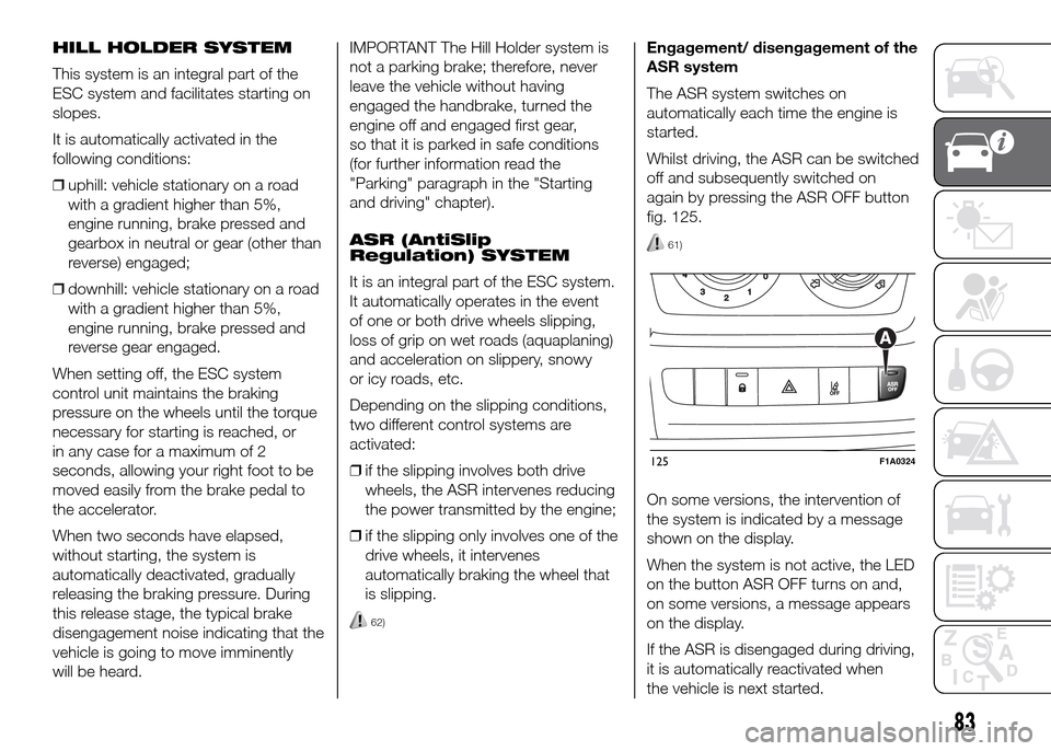
again by pressing the ASR OFF button
fig. 125.
61)
On some versions, the intervention of
the system is indicated by a message
shown on the display.
When the system is not active, the LED
on the button ASR OFF turns on and,
on some versions, a message appears
on the display.
If the ASR is disengaged during driving,
it is automatically reactivated when
the vehicle is next started.
125F1A0324
83
Page 88 of 387
When travelling on snowy roads with
snow chains, it may be helpful to turn
the ASR off: in fact, in these conditions,
the driving wheels slipping when
moving off gives you better traction.
HBA SYSTEM
(Hydraulic Brake Assist)
The HBA system is designed to
improve the vehicle’s braking capacity
during emergency braking. The system
detects emergency braking by
monitoring the speed and strength with
which the brake pedal is pressed,
thereby applying the optimal brake
pressure.
This can reduce the braking distance:
the HBA system therefore completes
the ABS.
Maximum assistance from the HBA
system is obtained by pressing the
brake pedal very quickly. In addition,
the brake pedal must be pressed
continuously during braking, avoiding
intermittent presses, to benefit from the
system.
Do not reduce pressure on the brake
pedal until braking is not necessary
anymore.
The HBA system is deactivated when
the brake pedal is released.
63) 64) 65)
ERM ELECTRONIC ROLLOVER
MITIGATION SYSTEM
(Electronic Rollover Mitigation)
The system monitors the tendency of
the wheels to rise from the ground if the
driver performs extreme manoeuvres
like quick steering to avoid an obstacle,
especially in poor road conditions.
If these conditions occur, the system
intervenes on the brakes and engine
power to reduce the possibility that the
wheels are raised from the ground.
It is not possible to avoid the tendency
to roll over if this is due to reasons
such as driving on high side gradients,
collision with objects or other vehicles.
66)
HILL DESCENT CONTROL
(HDC) SYSTEM
It is an integral part of the ESC and is
aimed at keeping the vehicle at a
constant speed during a descent,
operating autonomously on the brakes
in various ways at the same time. In this
way the vehicle stability and completely
safe driving are guaranteed, above all
in poor grip conditions and/or steep
descents.
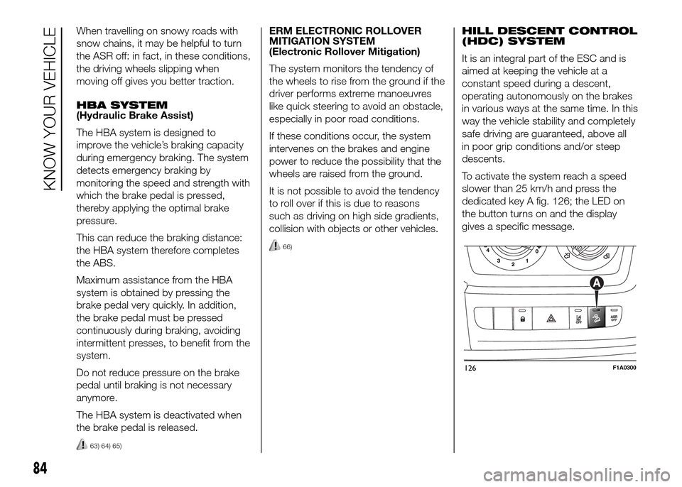
To activate the system reach a speed
slower than 25 km/h and press the
dedicated key A fig. 126; the LED on
the button turns on and the display
gives a specific message.
126F1A0300
84
KNOW YOUR VEHICLE