Main FIAT DUCATO 2017 Owner handbook (in English)
[x] Cancel search | Manufacturer: FIAT, Model Year: 2017, Model line: DUCATO, Model: FIAT DUCATO 2017Pages: 296, PDF Size: 14.44 MB
Page 129 of 296
 wait for the warning on the
instrument panel to switch off before
moving the vehicle, the warning light
may stay on for a few seconds to half a
minute. In case of motor start-up and
movement of the ve")
wait for the warning on the
instrument panel to switch off before
moving the vehicle, the warning light
may stay on for a few seconds to half a
minute. In case of motor start-up and
movement of the vehicle, the warning
light will remain on for a longer period of
time, but there are no problems on the
engine functionality. If topping up is
done with the UREA tank empty, you
have to wait two minutes before
starting the vehicle.
When refuelling the additive for
Diesel Emissions AdBlue (UREA)
with bottle:
park the vehicle on ground level;
turn off the engine by turning the key
in the OFF position;
open the fuel flap A fig. 116 and
then unscrew and remove the cap C
fig. 116 from the UREA filler;
screw the bottle of AdBlue (UREA)
into the filler until it is fully tightened (fig.
117, ref. 1);
press the bottom of the bottle
towards the filler to release the bottle's
safety valve and start topping up (fig.
117 ref. 2);
if the level of AdBlue in the bottle
does not drop while topping up, it
means that you have filled the reservoir,
so pull the bottle towards you to
re-close the bottle's safety valve and
unscrew the bottle from the filler (fig.
117, ref. 3);
after removing the bottle, refit the
cap C fig. 116 on the UREA filler by
turning it clockwise until it is fully
tightened;
turn the key in the pawl starter in the
ON position (no need to start the
engine);
wait for the warning on the
instrument panel to switch off before
moving the vehicle, the warning light
may stay on for a few seconds to half a
minute. In case of motor start-up and
movement of the vehicle, the warning
light will remain on for a longer period of
time, but there are no problems on the
engine functionality;
if topping up is done with the UREA
tank empty, you have to wait two
minutes before starting the vehicle;
NoteThe driving conditions (altitude,
vehicle speed, load, etc.) determine the
quantity of UREA used by the vehicle.
In order to use the additive for Diesel
Emissions (UREA) correctly, see "Fluids
and lubricants" in the "Technical data".
131)
IMPORTANT
Exceeding the maximum filling level
of the tank UREA, it can cause damage
to the tank and spilling UREA. Please
avoid topping up after filling the tank.
117F1A5005
127
Page 130 of 296
 DO NOT EXCEED THE MAXIMUM
LEVEL. The UREA freezes at under -11
° C. Although the system is designed
to operate below the freezing point
of the UREA, it is advisable not to fill the
tank beyond the ma")
DO NOT EXCEED THE MAXIMUM
LEVEL. The UREA freezes at under -11
° C. Although the system is designed
to operate below the freezing point
of the UREA, it is advisable not to fill the
tank beyond the maximum level
because if the UREA freezes the
system can be damaged.
If the UREA is spilled on painted
surfaces or aluminium, immediately
clean the area with water and use
absorbent material to collect the fluid
that has been spilled on the ground.
Do not try to start the engine if
UREA was accidentally added to the
Diesel fuel tank, this can result in
serious engine damage, contact
Dealership.
Use AdBlue only according to DIN
70 070 and ISO 22241-1. Other fluids
may cause damage to the system: also
exhaust emissions would no longer
comply with the law. The distribution
companies are responsible for the
compliance of their product. Observe
the precautions of storage and
maintenance, in order to preserve the
initial qualities. The manufacturer of the
vehicle does not recognise any
guarantee in case of malfunctions and
damage caused to the vehicle due
to the use of urea (AdBlue) not in
accordance with regulations.
Any introduction of diesel fuel inside
the tank AdBlue, causes irreversible
damage to the pumping unit circuit
AdBlue.
Do not add additives to AdBlue. Do
not dilute AdBlue with tap water as
this may damage the system of
purification of exhaust gases.
In case of damage to the sewage
system of exhaust gas resulting from
the use of additives / tap water, the
introduction of diesel fuel, or at least by
not fulfilling the requirements, the
warranty expires.
AdBlue tank topping (UREA) in cold
environments
Since AdBlue (UREA) starts to freeze
around the -11 °C, the vehicle is
equipped with an automatic system of
heating UREA that allows the system to
function properly at temperatures
below -11 °C.
If the vehicle remains idle for a long
period at temperatures below the -11
°C, the UREA in the tank might freeze.
If the tank UREA was filled beyond
the maximum level and freezes, it can
be damaged; for this reason it is
advisable not to exceed the maximum
level of the tank.
Pay extra attention to avoid exceeding
the maximum level when you use
portable containers for topping up.Fuel storage - Diesel Fuel
132)
In case of the storage of massive
amounts of fuel, good maintenance is
essential. The fuel contaminated with
water favours the proliferation of
"microbes". These microbes create a
"slime" that can clog the filter system
and fuel pipes. Remove water from the
supply tank and regularly replace the
filter pipe.
NoteWhen a diesel engine runs out of
fuel, air is blown through the fuel
system.
AdBlue storage (UREA)
AdBlue (UREA) is considered a very
stable product with a long shelf life. If is
stored at temperatures between -12
°C and 32 °C, it can be stored at least
for a year.
Since UREA can freeze at temperatures
at or below -11 °C, the system was
designed to operate also in these cold
environments, thanks to an automatic
heating system which operates when
the engine is started.
NoteWhen you need to keep the
AdBlue (UREA), it is important to know
that:
128
STARTING AND DRIVING
Page 132 of 296
 WARNING
128)Do not approach naked flames or lit
cigarettes to the fuel tank filler: fire risk.
Keep your face away from the fuel filler to
prevent breathing in harmful vapours.
129)To avoid fuel spill")
WARNING
128)Do not approach naked flames or lit
cigarettes to the fuel tank filler: fire risk.
Keep your face away from the fuel filler to
prevent breathing in harmful vapours.
129)To avoid fuel spillage and the
exceeding of the maximum level, avoid
topping up after filling the tank.
130)Any fuel pumping in portable
containers located on a floor can cause a
fire. Danger of burns. Always put the fuel
container on the ground during filling. Avoid
using contaminated fuel: a fuel
contaminated with water or earth can
cause serious damage to the motor supply.
Proper maintenance of the fuel filter, of
the engine and the fuel tank is essential.
131)If AdBlue overheats for a prolonged
period inside the tank to over 50 ° C (for
example due to direct solar irradiation),
AdBlue can decompose ammonia vapours.
Ammonia vapours have a pungent odour
when the cap of the AdBlue tank is
unscrewed, therefore be careful not to
inhale any ammonia vapours in the tank
outlet. In this concentration, however, the
ammonia vapors are not harmful or
dangerous to health.
132)Do not open the fuel system at high
pressure with the engine running. The
operation of the engine creates a high fuel
pressure. A jet of high-pressure fuel can
cause serious injury or death.
WARNING
34)Only refuel with automotive diesel
complying with the European specification
EN 590. The use of other products or
mixtures may damage the engine beyond
repair and consequently invalidate the
warranty, due to the damage caused. If
you accidentally introduce other types of
fuel into the tank, do not start the engine.
Empty the tank. If the engine has been run
for even an extremely limited amount of
time, you must not only drain the fuel tank,
but the rest of the supply circuit as well.
35)Methane refuelling stations are not
authorised to refill the cylinders when the
inspection date has expired. The check
valve prevents the methane from flowing
back to the fuel filler.
36)If the vehicle has been registered in a
country other than Italy, the certification
data, identification and inspection
procedures for the methane cylinders
should conform to the legislation in that
country. In any case, it should be
remembered that the life of the cylinders is
20 years from the production date as set
out in ECE Regulation no. 110.
ADDITIVE FOR
DIESEL EMISSIONS
ADBLUE (UREA)
The vehicle is equipped with a Selective
Catalytic Reduction system to meet
the strict Diesel emissions standards
required by the Agency for
Environmental Protection.
The purpose of the system of Selective
Catalytic Reduction is to reduce the
nitrogen oxides levels emitted by
engines; these elements are harmful to
our health and to the environment
even at minimum levels. A small
amount of additive for Diesel emissions
AdBlue (UREA) is injected upstream
of the catalyst exhaust outlet where,
when it turns into gas, converts
nitrogen oxides, that create smog, in
simple nitrogen and water vapour, two
natural components of air we breathe.
You can use your vehicle with the
peace of mind of knowing that you are
contributing to a cleaner and healthy
environment for future generations.
System description
The vehicle is equipped with an UREA
fuel injection system and a Selective
Catalytic Reduction catalyst to meet the
emission standards.
130
STARTING AND DRIVING
Page 133 of 296
 These two systems ensure compliance
with the diesel emissions requirements;
at the same it maintains fuel saving
levels, driveability, torque and power.
For the system messages and warnings
refer to t")
These two systems ensure compliance
with the diesel emissions requirements;
at the same it maintains fuel saving
levels, driveability, torque and power.
For the system messages and warnings
refer to the "Warning lights and
messages" paragraph in the "Knowing
the instrument panel" section.
Notes
When you stop the vehicle you
could hear a distinct click coming from
under the vehicle due to the UREA
injection system, this is normal.
The UREA injection system pump
continues to operate for a short period
of time after the engine is switched
off, to purge the circuit. This is normal,
and you can still hear its noise from
under the vehicle.
VERSION WITH
METHANE SYSTEM
(Natural Power)
37) 38)
INTRODUCTION
The "Natural Power" version of the Fiat
Ducato features two fuel system, one
primary natural gas (methane) system
and one emergency petrol system.
METHANE CYLINDERS
The vehicle is equipped with five
cylinders (total capacity of about 218
litres) located under the vehicle floor
and protected by two special shields.
The cylinders are the tank that contains
the methane in its compressed
gaseous state (nominal pressure of 200
bar at 15°C). The methane, stored in
the cylinders at high pressure, flows
through a dedicated pipe to reach the
pressure regulator/reduction unit which
supplies the 4 methane injectors at
low pressure (about 6 bar).
IMPORTANT If gas is smelled, switch
from methane operation to petrol
operation and immediately go to a Fiat
Dealership to have the vehicle checked
and possible system faults excluded.FUEL SWITCHING
LOGICS
Management of switching between the
two different fuel supplies is fully
automatic, and carried out by the
engine control unit.
When the residual amount of methane
drops below 1/5 of the cylinder
capacity, the lowest level and the edges
of the other levels flash to indicate the
reserve state and that refuelling fig. 119
is required.
If the methane runs out, it is
automatically switched to petrol; on the
display, all the empty segments stop
flashing and then the
indicator near
the CNG icon fig. 120 turns on.
Having reached the reserve methane
pressure threshold, and completely
filled the methane tank, the system
forces the switch to petrol for 5
seconds, with the aim of keeping the
petrol fuel supply system fully efficient.
119F1A0436
131
Page 136 of 296
 SAVING FUEL
GENERAL INFORMATION
The general factors that affect fuel
consumption are listed below.
Vehicle maintenance
Tyres
Unnecessary loads
Roof rack/ski rack
Electric devices
Climate control syste")
SAVING FUEL
GENERAL INFORMATION
The general factors that affect fuel
consumption are listed below.
Vehicle maintenance
Tyres
Unnecessary loads
Roof rack/ski rack
Electric devices
Climate control system
Devices for aerodynamic control
DRIVING STYLE
The main driving styles that affect fuel
consumption are listed below.
Starting
Do not warm up the engine at low or
high revs when the vehicle is stationary;
this causes the engine to warm up
more slowly, thereby increasing fuel
consumption and emissions.
Unnecessary actions
Avoid accelerating when stopped at
traffic lights or before switching off the
engine.Gear selection
In the same way improper use of a high
gear increases consumption, emissions
and engine wear.
Top speed
Fuel consumption increases
considerably with speed.
Acceleration
Accelerating violently will greatly affect
consumption and emissions:
acceleration should be gradual.
CONDITIONS OF USE
The main usage conditions that
negatively affect fuel consumption are
listed below.
Cold starting
Short journeys and frequent cold starts
do not allow the engine to reach
optimum operating temperature.
Traffic and road conditions
Rather high consumption levels are
linked to situations with heavy traffic, for
instance when travelling in queues
with frequent use of the lower gears or
in cities with many traffic lights. Winding
mountain roads and rough road
surfaces also adversely affect
consumption.Stops in traffic
During prolonged hold-ups (e.g. level
crossings) the engine should be
switched off.
134
STARTING AND DRIVING
Page 142 of 296
 Please note that the tow bar can be
installed only when in these conditions.
If the locking mechanism of the tow
bar is disengaged before the
installation, or at any other time, and is
in the locked p")
Please note that the tow bar can be
installed only when in these conditions.
If the locking mechanism of the tow
bar is disengaged before the
installation, or at any other time, and is
in the locked position, it must be
pre-loaded. The locked position can be
identified by the green mark of the
flywheel coinciding with the green mark
of the tow bar and by the flywheel in
the stop position on the tow bar,
namely without slot (see figure).
The locking mechanism is pre-loaded
as follows: with the key inserted and
the lock open, extract the flywheel
following the direction of the arrow and,
to pre-load, rotate according to the
direction of the arrow b until the stop.
The release lever is engaged and the
locking mechanism remains in the
pre-loading position even when the
flywheel is released. The tow bar must
be inserted in the housing pipe with the
coupling pin for the installation. Insert
from the bottom and push upwards.
The mechanism then locks
automatically. Keep your hands far from
the flywheel, as it rotates during the
locking procedure.2. The tow bar must be inserted in the
housing pipe with the coupling pin
for the installation. Insert from the
bottom and push upwards. The
mechanism then locks automatically.
Keep your hands far from the flywheel,
as it rotates during the locking
procedure.
3. Close the lock and always remove
the key. The key cannot be removed
when the lock is released. Apply the
protection cap on the lock.
Removing the tow bar
1. Remove the protection cap from the
lock and press it on the key grip. Open
the lock with the key.
2. Hold the tow bar firmly, remove the
flywheel following the direction of the
arrow and rotate according to the
direction of the arrow b until stopping,
so as to remove till the extracted
position. Then remove the tow bar from
the housing pipe. The flywheel can
then be released; it autonomously
stops in the released position.
3. Arrange the tow bar in the luggage
compartment so that it cannot be
dirtied or damaged by other
transported objects.
4. Insert the suitable plug in the
mounting pipe.
WARNING
40)The removable ball head bar must be
repaired and taken apart by the
manufacturer only.
41)The accompanying plate must be in a
highly visible point of the vehicle, near
the mounting pipe or inside the luggage
compartment.
42)To ensure correct operation of the
system, periodically remove all dirt deposits
from the ball head bar and from the
mounting pipe. The mechanical
components must be serviced at the
specified intervals. The lock must only be
treated with graphite.
43)Periodically lubricate the joints, the
sliding surfaces and the balls with grease
without resin or oil. Lubrication is also a
further corrosion protection.
44)If the vehicle is washed with high-
pressure jets, the ball head bar must be
removed and the dedicated cap fitted. The
ball head bar must never be treated with
steam jets.
45)Two keys are supplied together with
the removable ball tow bar. Note down the
key number on the pawl for any following
order and keep it.
140
STARTING AND DRIVING
Page 147 of 296
 Light bulbs
 Type Power Figure ref.
Main beam headlights H7 55W D
Dipped beam headlights H7 55W D
Front side lights / daytime running lights
W21/5W - LED
(#)--
Front fog lights
(*)H11 55W -")
Light bulbs
Light bulbs Type Power Figure ref.
Main beam headlights H7 55W D
Dipped beam headlights H7 55W D
Front side lights / daytime running lights
W21/5W - LED
(#)--
Front fog lights
(*)H11 55W -
Front direction indicators WY21W 21W B
Side turn lightW16WF
(**) / WY5W
(***)16W(**) / 5W (***)A
Rear direction indicators PY2IW 21W B
Side lights W5W 5W A
Rear side lights P21/5W 21/5W B
Rear side lights/Brake lights P21W 21W B
Third brake light W5W 5W B
Reverse gear W16W 16W B
Rear fog light W16W 16W B
Number plate C5W 5W A
Front roof light (movable lens) 12V10W 10W C
Rear ceiling light 12V10W 10W C
(#) where provided, instead of bulb W21/5W
(*)for versions/markets, where provided
(**)XL and Tempo Libero versions
(***)all other versions
145
Page 148 of 296
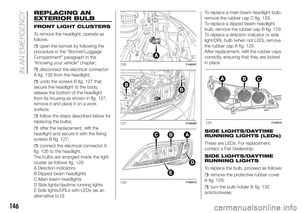
REPLACING AN
EXTERIOR BULB
FRONT LIGHT CLUSTERS
To remove the headlight, operate as
follows:
open the bonnet by following the
procedure in the "Bonnet/Luggage
Compartment" paragraph in the
"Knowing your vehicle" chapter;
disconnect the electrical connector
A fig. 126 from the headlight;
undo the screws B fig. 127 that
secure the headlight to the body,
release the bottom of the headlight
from its housing as shown in fig. 127,
remove it and place it on a work
surface;
follow the steps described below for
replacing the bulbs;
after the replacement, refit the
headlight and secure it with the fixing
screws B fig. 127;
connect the electrical connector A
fig. 126 to the headlight.
The bulbs are arranged inside the light
cluster as follows fig. 128:
A Direction indicators
B Dipped beam headlights
C Main beam headlights
D Side lights/daytime running lights
E Side lights/DRLs with LEDs (as an
alternative to D)To replace a main beam headlight bulb,
remove the rubber cap C fig. 129.
To replace a dipped beam headlight
bulb, remove the rubber cap B fig. 129.
To replace a direction indicator or side
light/DRL bulb (when not LED), remove
the rubber cap A fig. 129.
After replacement, refit the rubber caps
correctly, ensuring that they are locked
in place.
SIDE LIGHTS/DAYTIME
RUNNING LIGHTS (LEDs)
These are LEDs. For replacement,
contact a Fiat Dealership.
SIDE LIGHTS/DAYTIME
RUNNING LIGHTS
To replace the bulb, proceed as follows:
remove the protective rubber cover
A fig. 129;
turn the bulb holder B fig. 130
anticlockwise;
126F1A0337
127F1A0338
128F1A0313
129F1A0314
146
IN AN EMERGENCY
Page 149 of 296
 extract the bulb by pulling and
replace it;
remove the bulb by pushing it
slightly and turning it anticlockwise
(bayonet mount);
refit the bulb holder B by turning it
clockwise and making sure that it")
extract the bulb by pulling and
replace it;
remove the bulb by pushing it
slightly and turning it anticlockwise
(bayonet mount);
refit the bulb holder B by turning it
clockwise and making sure that it locks
correctly
refit the protective rubber cover A
fig. 129.
MAIN BEAM HEADLIGHTSTo replace the bulb, proceed as follows:
remove the protective rubber cover
C fig. 129;
free the bulb holder A fig. 131 from
the side clips B and remove it;
disconnect the electrical connector;
fit the new bulb, ensuring that the
outline of the metal part coincides with
the grooves on the curve of the
headlight, pressing to engage it with the
side clips;
reconnect the electrical connector;
refit the protective rubber cover
C fig. 129.
DIPPED BEAM
HEADLIGHTS
With incandescent bulbs
To replace the bulb, proceed as follows:
remove the protective rubber cover
B fig. 129;
free the bulb holder A fig. 132 from
the side clips B and remove it;
disconnect the electrical connector;
fit the new bulb, ensuring that the
outline of the metal part coincides with
the grooves on the curve of the
headlight, pressing to engage it with the
side clips;
reconnect the electrical connector;
refit the protective rubber cover
B fig. 129.
DIRECTION INDICATORS
To replace the bulb, proceed as follows:
remove the protective rubber cover
A fig. 129;
turn the bulb holder B fig. 133
anticlockwise;
extract the bulb by pulling and
replace it;
remove the bulb by pushing it
slightly and turning it anticlockwise
(bayonet mount);
refit the bulb holder B by turning it
clockwise and making sure that it locks
correctly
refit the protective rubber cover A
fig. 129.
130F1A0386
131F1A0315
132F1A0316
147
Page 157 of 296
 Dashboard fusebox
Protected device Fuse Ampere
Right dipped beam headlight F12 7.5
Left dipped headlight F13 7.5
Engine compartment control unit relay, dashboard control unit relay
(+key)F31 5
Lightin")
Dashboard fusebox
Protected device Fuse Ampere
Right dipped beam headlight F12 7.5
Left dipped headlight F13 7.5
Engine compartment control unit relay, dashboard control unit relay
(+key)F31 5
Lighting of roof lights in the passenger compartment (+battery) F32 7.5
Battery monitoring sensor for Start&Stop versions (+battery) F33 7.5
Minibus interior lights (emergency) F34 7.5
Radio, Climate control system, Alarm, Tachograph, Battery
disconnecting control unit, Timer Webasto timer (+battery), TPMS,
Current stabiliser for radio setup (S&S)F36 10
Brake lights control (main), Instrument panel (+key), Gateway (for
transformers)F37 7.5
Door lock (+battery) F38 20
Windscreen wiper (+key) F43 20
Driver's side electric window F47 20
Passenger side electric window F48 20
Parking sensor control unit, radio, steering wheel controls, central
control panel, left control panel, auxiliary panel, battery
disconnecting control unit (+key), Trailer hook, Rain sensor, Current
stabiliser (for S&S)F49 5
155