window FIAT DUCATO BASE CAMPER 2014 Owner handbook (in English)
[x] Cancel search | Manufacturer: FIAT, Model Year: 2014, Model line: DUCATO BASE CAMPER, Model: FIAT DUCATO BASE CAMPER 2014Pages: 367, PDF Size: 20.39 MB
Page 40 of 367
Air flow distributed between
windscreen and front side window
defroster/demister and central and side
dashboard vents. This distribution
allows good air diffusion and maintains
a good level of comfort both in summer
and winter.
The distribution set is shown by the
corresponding LEDs on the selected
buttons coming on.
To restore automatic control of the air
distribution after a manual selection,
press the AUTO button.
Fan speed adjustment
buttons (H)
Press the H button to increase or to
decrease the fan speed and therefore
the amount of air sent into the
passenger compartment, though the
required temperature remains set.
The fan speed is shown by the lit bars
on the display:
❒Maximum fan speed = all the bars lit
up;
❒Minimum fan speed = one bar lit up.
The fan can only be excluded if the
climate control system compressor has
been switched off by pressing the F
button.IMPORTANT To restore automatic
control of the fan speed after a manual
adjustment, press the AUTO button.
IMPORTANT At high vehicle speeds,
the dynamic effect may increase the
flow of air into the passenger
compartment which in this case will not
directly correspond to the fan speed
bar display.
AUTO button (A)
(automatic operation)
Press AUTO to make the system
automatically adjust the quantity and
distribution of the air introduced into the
passenger compartment. All previous
manual settings will be cancelled.
The message FULL AUTO will appear
on the front display in this condition.
By manually adjusting at least one
of the functions automatically managed
by the system (air recirculation, air
distribution, fan speed or switching off
the compressor), the word FULL will
disappear from the display, indicating
that the system is no longer
automatically controlling all the
functions (the temperature will still be
controlled automatically).IMPORTANT Should the system (after
manual settings) no longer be able
to guarantee the required temperature
set in the passenger compartment,
the set temperature value will start
flashing to indicate the difficulties the
system is experiencing and then the
word AUTO will disappear.
To restore system automatic control at
any time, after one or more manual
adjustments, press the AUTO button.
Air recirculation on/off
button (G)
The air recirculation is managed
according to the following operating
logic:
❒override on (inside air recirculation
always on), indicated by the LED
on button G and the
symbol on
the display;
❒override off (air recirculation
constantly off with air intake from the
outside), signalled by the LED in
the button switching off and by the
symbol in the display
disappearing.
These operating conditions are
obtained by pressing air recirculation
button G in sequence.
36
KNOW YOUR VEHICLE
Page 41 of 367
IMPORTANT The engagement of the air
recirculation system makes it possible
to reach the required heating or cooling
conditions faster.
It is however inadvisable to use it on
rainy/cold days as it would considerably
increase the possibility of the windows
misting inside, especially if the climate
control compressor is off.
To prevent the windows from misting
up, the recirculation is forced off (i.e. air
is drawn in from the outside) when
the outside temperature is cold.
It is advisable not to use the air
recirculation function when the outside
temperature is low to prevent the
windows from rapidly misting up.
Climate control
compressor
enablement/off button
(F)
Press button
to switch the climate
control compressor off (if on). The icon
on the display will go out.
Press the button when the LED is off to
restore automatic system control of
compressor activation. The icon will
light up on the display.The system will switch recirculation off
when the compressor is switched off to
prevent windows from misting up.
Although the system is capable
of maintaining the required
temperature, the word FULL will
disappear from the display. If, on the
other hand, it is no longer capable
of maintaining the temperature, the
letters flash and the word AUTO goes
out.
IMPORTANT With the compressor off, it
is not possible to introduce air cooler
than ambient temperature into the
passenger compartment. Furthermore,
in certain conditions, the windows
could mist up rapidly because the air is
not dehumidified.
The system remembers that the
compressor has been switched off,
even after the engine has stopped.
To restore automatic compressor
control, press the
button again (in
this case, the system will only work as a
heater) or press the AUTO button.
With the compressor switched off, if the
outside temperature is higher than the
one set, the system is not capable
of satisfying this request. This is
signalled by the target temperature
flashing, after which the word AUTO
goes out.With the climate control compressor
off, the fan speed can be set to zero
manually (no bar shown).
With the compressor enabled and the
engine started, the fan speed may
be reduced to the minimum setting
(only one bar shown).
Button for rapid window
demisting/defrosting (D)
Press this button and the climate
control system will automatically switch
on all the functions required for fast
windscreen and side window
demisting/defrosting:
❒switches on climate control
compressor when climatic conditions
are suitable;
❒switches air recirculation off;
❒maximum air temperature HI in both
areas;
❒sets the fan speed according to the
engine coolant temperature to limit
the flow of air that is not sufficiently
warm to demist the windows;
❒directs air flow to windscreen and
front side windows vents;
❒heated rear window on.
37
Page 42 of 367
IMPORTANT The rapid demisting/
defrosting function for the windows
remains on for about 3 minutes from
when the engine coolant reaches the
appropriate temperature for a rapid
demisting of the windows.
When this function is active, the LED on
the corresponding button and the one
on the heated rear window button
switch on. The message FULL AUTO
goes off on the display.
You can only adjust the fan speed and
switch off the heated rear window
manually when this function is active.
To restore the previous operating
conditions, simply press button B, air
recirculation button G, compressor
button F or AUTO button A.
NoteTo guarantee rapid demisting/
defrosting, if an additional heater/air
conditioner is present (under the front
or rear seat on Panorama and Combi
versions), if activated, deactivate it
using button F (LED off) located
in control panel F fig. 55.Switching the system
OFF (E)
Press button E to switch the climate
control system off. The display will go
out.
The following climate control conditions
will be present when the system is off:
❒display off;
❒temperature setting not displayed;
❒air recirculation on, thereby insulating
the passenger compartment from the
outside (recirculation LED on);
❒climate control compressor off;
❒fan off.
Press the AUTO button to switch the
climate control system back on in
full automatic mode.
ADDITIONAL
HEATER(for versions/markets, where provided)
On some versions, an additional heater
is also present beneath the driver's
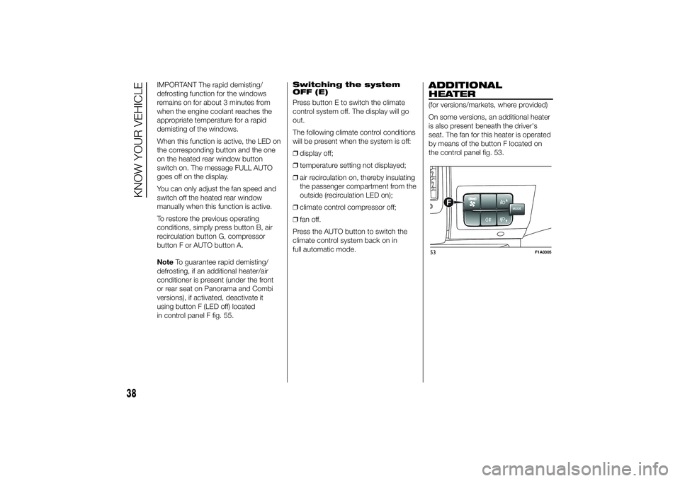
seat. The fan for this heater is operated
by means of the button F located on
the control panel fig. 53.
MODE
F
53
F1A0305
38
KNOW YOUR VEHICLE
Page 43 of 367
INDEPENDENT
ADDITIONAL
HEATER(for versions/markets, where provided)
The vehicle is available, on request,
with two different independent heaters:
one fully automatic, the other which
can be programmed.
AUTOMATIC VERSION
The additional heater is turned on in
automatic mode when the engine
is started and the required outside
temperature and coolant conditions are
present. Deactivation is always
automatic.
21)
IMPORTANT During periods with low
outdoor temperatures when the device
cuts in, check that the fuel level is
always higher than the reserve level.
Otherwise the device could lock and
require the assistance of a Fiat
Dealership.
PROGRAMMABLE
VERSION
The additional heater operates
completely independently of engine
operation and allows the following:❒heating the passenger compartment
with the engine off
❒defrosting the windows;
❒heat the engine coolant and then the
engine itself prior to starting.
The system consists of:
❒a diesel burner for heating the water
with an exhaust silencer for the
combustion gases;
❒a metering pump connected to the
reservoir pipes for supplying the
burner;
❒a heat exchanger connected to the
engine cooling system pipes;
❒a control unit connected to the
passenger compartment
heating/ventilation system to allow
automatic operation;
❒an electronic control unit for
controlling and adjusting the built-in
burner;
❒a digital timer fig. 54 for turning the
heater on manually or for
programming the time that it comes
on.The additional heater (during winter)
heats, maintains the temperature of and
circulates engine coolant for a set time
period in order to ensure optimum
engine and passenger compartment
conditions at engine start-up.
The heater can operate automatically
when programmed with a digital timer
or manually by pressing the 'immediate
heating' button on the timer.
After heater activation, whether
programmed or manually, the electronic
control unit operates the coolant pump
and turns on the burner in accordance
with pre-set, controlled procedures.
The circulation pump output is also
controlled by the electronic control unit
in order to minimise the initial heating
time.
When the system operates, the control
unit turns on the passenger
compartment heater unit fan at the
second speed.
The thermal power of the boiler is
regulated automatically by the
electronic control unit depending on the
temperature of the engine coolant.
39
Page 52 of 367
WINDOW CLEANING
IN BRIEF
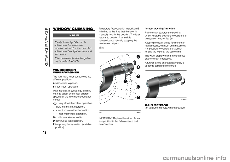
The right lever fig. 64 controls
activation of the windscreen
wiper/washer and, where provided,
activation of headlight washers and
rain sensor.
This operates only with the ignition
key turned to MAR-ON.
WINDSCREEN
WIPER/WASHER
The right hand lever can take up five
different positions:Awindscreen wiper off.Bintermittent operation.
With the stalk in position B, turn ring
nut F to select one of four different
speeds for the intermittent operation
mode:
very slow intermittent operation.
--
slow intermittent operation.
---
medium intermittent operation.
----
fast intermittent operation.
Ccontinuous slow operation.Dcontinuous fast operation.Etemporary fast operation (unstable
position).Temporary fast operation in position E
is limited to the time that the lever is
manually held in this position. The lever
returns to position A when it is
released, automatically stopping the
windscreen wipers.
3)
IMPORTANT Replace the wiper blades
as specified in the “Maintenance and
care” section.“Smart washing” function
Pull the stalk towards the steering
wheel (unstable position) to operate the
windscreen washer fig. 65.
Keeping the lever pulled for more than
half a second, with just one movement
it is possible to operate the washer
jet and the wiper at the same time.
The wiper stops working three strokes
after the stalk is released.
A further stroke after approximately 6
seconds completes the cycle.
RAIN SENSOR
(for versions/markets, where provided)64
F1A0071
65
F1A0072
48
KNOW YOUR VEHICLE
Page 59 of 367
Warning lights
and
are lit up in the
instrument panel when this device is
activated. Press switch A again to turn
the lights off.
IMPORTANT The use of hazard warning
lights is governed by the highway
code of the country you are in. Comply
with legal requirements.
Emergency braking
(for versions/markets, where provided)
In the event of emergency braking
the hazard warning lights come on
automatically, as do theand
warning lights in the panel. The
function switches off automatically
when the nature of the braking
changes. This function complies with
the relevant legislation currently in force.
FOG LIGHTS
(for versions/markets, where provided)
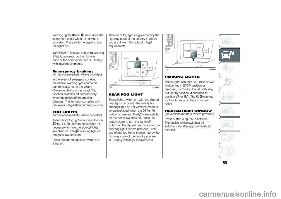
To turn front fog lights on, press buttonfig. 74. To activate these lights it is
necessary to have the side/taillights
switched on. The
warning light on
the panel switches on.
Press the button again to switch the
lights off.The use of fog lights is governed by the
highway code of the country in which
you are driving. Comply with legal
requirements.
REAR FOG LIGHT
These lights switch on, with the dipped
headlights on or with the side lights
and fog lights on (for versions/markets,
where provided) when the
fig. 75
button is pressed. The
warning light
on the panel switches on. Press the
button again to turn the lights off,
or turn off the dipped beams and/or the
front fog lights (where provided). The
use of rear fog lights is governed by the
highway code of the country you are
in. Comply with legal requirements.PARKING LIGHTS
These lights can only be turned on with
ignition key in STOP position or
removed, by moving the left stalk ring
nut first to positionOand then to
position
or
. The
warning
light switches on in the instrument
panel.
HEATED REAR WINDOW
(for versions/markets, where provided)
Press button A fig. 76 to activate.
The device will be switched off
automatically after approximately 20
minutes.
MODE
74
F1A0331
MODE
75
F1A0323
55
Page 60 of 367
BATTERY
DISCONNECTION
FUNCTION
(DISCONNECTOR)
(for versions/markets, where provided)
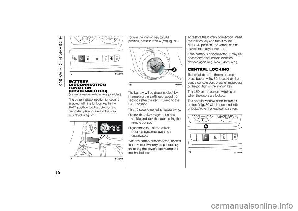
The battery disconnection function is
enabled with the ignition key in the
BATT position, as illustrated on the
dedicated plate located in the area
illustrated in fig. 77.To turn the ignition key to BATT
position, press button A (red) fig. 78.
The battery will be disconnected, by
interrupting the earth lead, about 45
seconds after the key is turned to the
BATT position.
This 45 second period is necessary to:
❒allow the driver to get out of the
vehicle and lock the doors using the
remote control;
❒guarantee that all the vehicle
electrical systems have been
deactivated.
With the battery disconnected, access
to the vehicle will only be possible by
unlocking the driver's door using the
mechanical lock.To restore the battery connection, insert
the ignition key and turn it to the
MAR-ON position, the vehicle can be
started normally at this point.
If the battery is disconnected, it may be
necessary to set certain electrical
devices again (e.g. clock, date, etc.).
CENTRAL LOCKING
To lock all doors at the same time,
press button A fig. 79, located on the
centre console control panel, regardless
of the position of the ignition key.
The LED on the button switches on
when the doors are locked.
The electric window panel features a
button D fig. 80 which independently
unlocks/locks the load compartment.76
F1A0330
77
F1A0082
78
F1A0083
79
F1A0303
56
KNOW YOUR VEHICLE
Page 63 of 367
CUP HOLDER - CAN
HOLDER - BOTTLE
HOLDER ON
DASHBOARD
(for versions/markets, where provided)
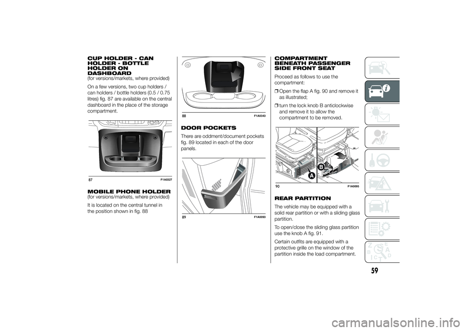
On a few versions, two cup holders /
can holders / bottle holders (0.5 / 0.75
litres) fig. 87 are available on the central
dashboard in the place of the storage
compartment.
MOBILE PHONE HOLDER
(for versions/markets, where provided)
It is located on the central tunnel in
the position shown in fig. 88DOOR POCKETS
There are oddment/document pockets
fig. 89 located in each of the door
panels.COMPARTMENT
BENEATH PASSENGER
SIDE FRONT SEAT
Proceed as follows to use the
compartment:
❒Open the flap A fig. 90 and remove it
as illustrated;
❒turn the lock knob B anticlockwise
and remove it to allow the
compartment to be removed.
REAR PARTITION
The vehicle may be equipped with a
solid rear partition or with a sliding glass
partition.
To open/close the sliding glass partition
use the knob A fig. 91.
Certain outfits are equipped with a
protective grille on the window of the
partition inside the load compartment.87
F1A0327
88
F1A0343
89
F1A0093
90
F1A0095
59
Page 71 of 367
DEAD LOCK
(for versions/markets, where provided)
This safety device inhibits the operation
of:
❒interior handles
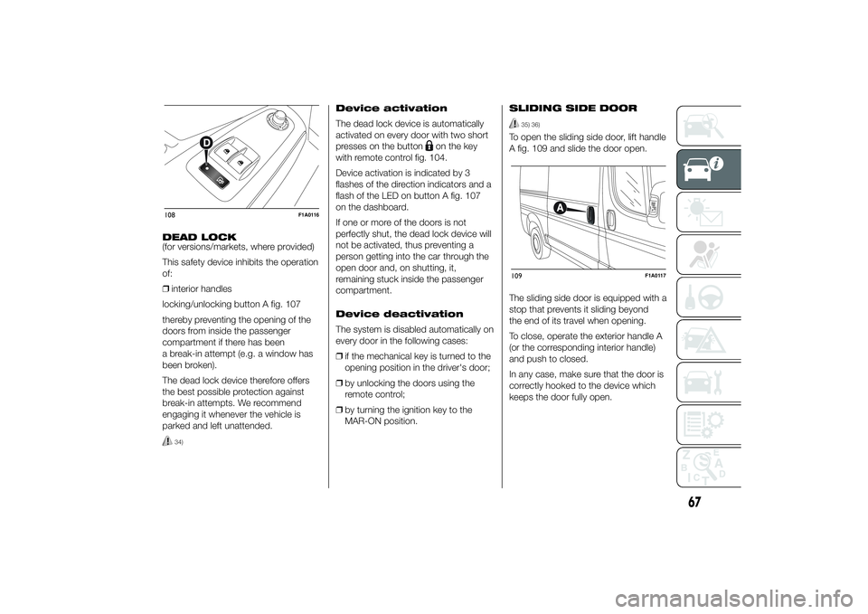
locking/unlocking button A fig. 107
thereby preventing the opening of the
doors from inside the passenger
compartment if there has been
a break-in attempt (e.g. a window has
been broken).
The dead lock device therefore offers
the best possible protection against
break-in attempts. We recommend
engaging it whenever the vehicle is
parked and left unattended.
34)
Device activation
The dead lock device is automatically
activated on every door with two short
presses on the button
on the key
with remote control fig. 104.
Device activation is indicated by 3
flashes of the direction indicators and a
flash of the LED on button A fig. 107
on the dashboard.
If one or more of the doors is not
perfectly shut, the dead lock device will
not be activated, thus preventing a
person getting into the car through the
open door and, on shutting, it,
remaining stuck inside the passenger
compartment.
Device deactivation
The system is disabled automatically on
every door in the following cases:
❒if the mechanical key is turned to the
opening position in the driver's door;
❒by unlocking the doors using the
remote control;
❒by turning the ignition key to the
MAR-ON position.SLIDING SIDE DOOR
35) 36)
To open the sliding side door, lift handle
A fig. 109 and slide the door open.
The sliding side door is equipped with a
stop that prevents it sliding beyond
the end of its travel when opening.
To close, operate the exterior handle A
(or the corresponding interior handle)
and push to closed.
In any case, make sure that the door is
correctly hooked to the device which
keeps the door fully open.
108
F1A0116
109
F1A0117
67
Page 72 of 367
SLIDING SIDE WINDOW
(for versions/markets, where provided)
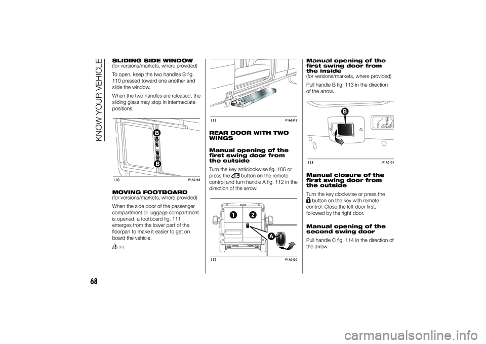
To open, keep the two handles B fig.
110 pressed toward one another and
slide the window.
When the two handles are released, the
sliding glass may stop in intermediate
positions.
MOVING FOOTBOARD
(for versions/markets, where provided)
When the side door of the passenger
compartment or luggage compartment
is opened, a footboard fig. 111
emerges from the lower part of the
floorpan to make it easier to get on
board the vehicle.
37)
REAR DOOR WITH TWO
WINGS
Manual opening of the
first swing door from
the outside
Turn the key anticlockwise fig. 106 or
press the
button on the remote
control and turn handle A fig. 112 in the
direction of the arrow.Manual opening of the
first swing door from
the inside
(for versions/markets, where provided)
Pull handle B fig. 113 in the direction
of the arrow.
Manual closure of the
first swing door from
the outside
Turn the key clockwise or press the
button on the key with remote
control. Close the left door first,
followed by the right door.
Manual opening of the
second swing door
Pull handle C fig. 114 in the direction of
the arrow.
110
F1A0118
111
F1A0119
112
F1A0120
113
F1A0121
68
KNOW YOUR VEHICLE