technical data FIAT DUCATO BASE CAMPER 2014 Owner handbook (in English)
[x] Cancel search | Manufacturer: FIAT, Model Year: 2014, Model line: DUCATO BASE CAMPER, Model: FIAT DUCATO BASE CAMPER 2014Pages: 367, PDF Size: 20.39 MB
Page 1 of 367

The data contained in this publication is intended merely as a guide. FIAT reserves the right to modify the models and
versions described in this booklet at any time for technical and commercial reasons.
If you have any further questions please consult your FIAT dealer.
Printed in recycled paper without chlorine.
OWNER HANDBOOK
FIATDUCATO
ENGLISH
DUCATO LUM GB 17-12-2008 9:57 Pagina 1
Page 5 of 367
Dear Customer,We would like to congratulate and thank you for choosing a Fiat Ducato. We have written this handbook to help you get to know all the
features of your vehicle and use it in the best possible way. You should read it right through before taking to the road for the first time.
You will find information, tips and important warnings regarding the use of your vehicle to help you get the most from the technological features
of your Fiat Ducato. It also provides a description of special features and essential information for the care and maintenance of your vehicle
over time as well as for safe driving.
We urge you to read the warnings and indications found throughout the text with care, marked with the following symbols:
personal safety;vehicle integrity;environmental protection.
NOTE These symbols, when necessary, are reported at the end of each paragraph and are followed by a number. That number recalls the
corresponding warning at the end of the relevant section.
In the attached Warranty Booklet you will also find a description of the Services that Fiat offers to its customers, the Warranty Certificate and
the detail of the terms and conditions for maintaining its validity.
We are sure that these will help you to get in touch with and appreciate your new vehicle and the service provided by the people at Fiat.
Enjoy reading. Happy motoring!
This Owner Handbook describes all Fiat Ducato versions. As a consequence, you should only consider the information
which is related to the trim level, engine and version that you have purchased. All data contained in this publication is
purely indicative. Fiat Group Automobiles can modify the specifications of the vehicle model described in this publication
at any time, for technical or marketing purposes. For further information, contact a Fiat Dealership.
Page 9 of 367
GRAPHICAL INDEX
.
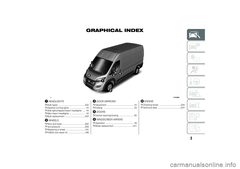
HEADLIGHTS
❒Bulb types ..........................................202
❒Daytime running lights ......................... 44
❒Side lights/dipped beam headlights .... 44
❒Main beam headlights ......................... 45
❒Bulb replacement ................................205
WHEELS
❒Rims and tyres ....................................262
❒Tyre pressure ......................................263
❒Replacing a wheel ...............................191
❒Fix&Go tyre repair kit ...........................196
DOOR MIRRORS
❒Adjustment ......................................... 24
❒Folding ............................................... 25
DOORS
❒Central opening/closing ...................... 65
WINDSCREEN WIPERS
❒Operation ........................................... 48
❒Blade replacement ..............................241
ENGINE
❒Checking levels ...................................229
❒Technical data .....................................254
1
F1A5000
5
Page 179 of 367
LOADING ADVICEThe Fiat Ducato version used by you
has been designed and type approved
on the basis of certain maximum
weights (see "Weights" table in the
"Technical Data" chapter): kerb weight,
payload, total weight, maximum weight
on front axle, maximum weight on
rear axle, towable weight.
IMPORTANT The maximum permitted
load on the floor fastenings is 500
kg; the maximum permitted load on the
side panel is 150 kg.
IMPORTANT For versions with right and
left side flaps, it is advisable to
reposition the release lever in the closed
position before lowering the sides.
35)128) 129) 130)
In addition to these general
precautions, some simple precautions
can improve driving safety, travelling
comfort and vehicle durability:
❒distribute the load evenly over the
platform: if it is necessary to
concentrate it in a single area,
choose an area mid-way between
both axles;❒lastly, remember that the vehicle’s
dynamic behaviour is affected by
the weight transported: in particular,
the stopping distances are longer,
especially at high speed.
IMPORTANT
35) Each of these must be strictly
observed and MUST NEVER BE
EXCEEDED in any case. In
particular, ensure that you never
exceed the maximum permitted
weights on the front and rear
axles when arranging the load on
the vehicle (particularly if the
vehicle is equipped with a specific
trim level).
WARNING
128) Irregular trajectories and abrupt
braking may cause sudden
movements of the load with
consequent situations of hazard
for the driver and passengers:
before setting off, secure the load
tightly using the appropriate
hooks on the floor and use steel
cables, ropes or chains strong
enough to hold the items to be
secured.
129) If a vehicle is parked on a very
steep gradient or with a side
gradient, opening the rear door or
side door could cause any
unsecured items to emerge
suddenly.
130) If you wish to carry a reserve of
petrol in a can, observe the legal
restrictions and only use a can
that is type-approved and
properly secured to the load
anchorage eyebolts. Anyway, by
doing so, you increase the risk
of fire in the event of an accident
with your vehicle.
175
Page 183 of 367
IMPORTANT Electric brakes or other
devices must be used with engine
running.
In addition to the electrical branches,
the vehicle's electric system can only
be connected to the supply cable for an
electric brake and to the cable for an
internal light, though not above 15
W. For connections use the preset
control unit with battery cable no less
than 2.5 mm
2.
IMPORTANT The trailer tow hook
contributes to the length of the vehicle.
When installing on long wheelbase
versions, it is only possible to install
removable tow hooks because the total
vehicle length limit of 6 metres is
exceeded.
If no trailer is fitted, the hook must be
removed from the attachment base and
it must not exceed the vehicle's
original length.IMPORTANT If you wish to leave the
tow hook fitted without towing a trailer,
it is advisable to contact a Fiat
Dealership for the relevant system
update operations because the tow
hook could be detected as an obstacle
by the central sensors.Installation diagram for
Van versions fig. 172
The tow hook structure must be
fastened in the points shown by the
symbol Ø using a total of 6 M10x1.25
screws and 4 M12 screws.
The internal back plates must be at
least 5 mm thick. MAX LOAD ON
BALL: 100/120 kg according to the
payload (see “Weights” table in the
“Technical data” section).
133)
To install a tow hook, the bumpers
must be trimmed as described in the
supplier's installation kit.
Installation diagram for
Truck and Chassis Cab
versions fig. 173
Another tow hook specific to Truck and
Chassis Cab versions in shown in fig.
173.
The structure Ø must be fixed in the
points indicated using a total of 6
M10x1.25 screws and 4 M12 screws.
MAX LOAD ON BALL: 100/120 kg
according to the payload (see
“Weights” table in the “Technical data”
section).
134)
179
Page 200 of 367
FIX&GO
AUTOMATIC QUICK
TYRE REPAIR KIT(for versions/markets, where provided)
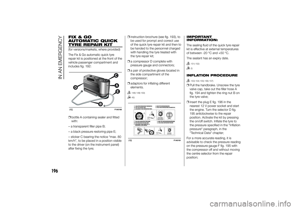
The Fix & Go automatic quick tyre
repair kit is positioned at the front of the
vehicle passenger compartment and
includes fig. 192:
❒bottle A containing sealer and fitted
with:
– a transparent filler pipe B;
– a black pressure restoring pipe E;
– sticker C bearing the notice “max. 80
km/h”, to be placed in a position visible
to the driver (on the instrument panel)
after fixing the tyre;❒instruction brochure (see fig. 193), to
be used for prompt and correct use
of the quick tyre repair kit and then to
be handed to the personnel charged
with handling the tyre treated with
the tyre repair kit;
❒a compressor D complete with
pressure gauge and connectors;
❒a pair of protective gloves located in
the side compartment of the
compressor;
❒adaptors for inflating different
elements.
148) 149) 150)43)
IMPORTANT
INFORMATION:
The sealing fluid of the quick tyre repair
kit is effective at external temperatures
of between -20 °C and +50 °C.
The sealant has an expiry date.
151) 152)2)
INFLATION PROCEDURE
153) 154) 155) 156) 157)
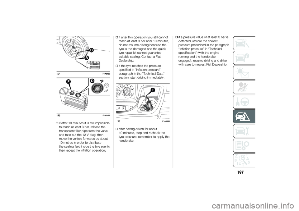
❒Pull the handbrake. Unscrew the tyre
valve cap, take out the filler hose A
fig. 194 and tighten the ring nut B on
the tyre valve;
❒insert the plug E fig. 196 in the
nearest 12 V power socket and start
the engine. Turn the selector D fig.
195 anticlockwise to the repair
position. Activate the kit by pressing
the on/off switch. Inflate the tyre to
the pressure specified in the "Inflation
pressure" paragraph, in the
"Technical Data" chapter;
For a more accurate reading, it is
advisable to check the pressure reading
on the pressure gauge F fig. 195 with
the compressor off and without moving
the centre selector from the repair
position;
192
F1A0180
193
F1A0181
196
IN AN EMERGENCY
Page 201 of 367
❒if after 10 minutes it is still impossible
to reach at least 3 bar, release the
transparent filler pipe from the valve
and take out the 12 V plug, then
move the vehicle forwards by about
10 metres in order to distribute
the sealing fluid inside the tyre evenly,
then repeat the inflation operation;❒if after this operation you still cannot
reach at least 3 bar after 10 minutes,
do not resume driving because the
tyre is too damaged and the quick
tyre repair kit cannot guarantee
suitable sealing. Contact a Fiat
Dealership;
❒if the tyre reaches the pressure
specified in “Inflation pressure”
paragraph in the "Technical Data"
section, start driving immediately;
❒after having driven for about
10 minutes, stop and recheck the
tyre pressure; remember to apply the
handbrake;❒if a pressure value of at least 3 bar is
detected, restore the correct
pressure prescribed in the paragraph
“Inflation pressure” in “Technical
specification” (with the engine
running and the handbrake
engaged), resume driving and drive
with care to nearest Fiat Dealership.194
F1A0182
195
F1A0183
196
F1A0335
197
Page 202 of 367
FOR CHECKING AND
RESTORING PRESSURE
ONLY
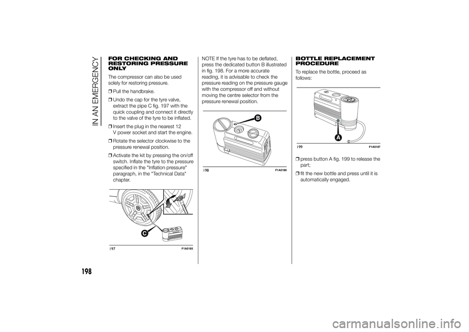
The compressor can also be used
solely for restoring pressure.
❒Pull the handbrake.
❒Undo the cap for the tyre valve,
extract the pipe C fig. 197 with the
quick coupling and connect it directly
to the valve of the tyre to be inflated.
❒Insert the plug in the nearest 12
V power socket and start the engine.
❒Rotate the selector clockwise to the
pressure renewal position.
❒Activate the kit by pressing the on/off
switch. Inflate the tyre to the pressure
specified in the "Inflation pressure"
paragraph, in the "Technical Data"
chapter.NOTE If the tyre has to be deflated,
press the dedicated button B illustrated
in fig. 198. For a more accurate
reading, it is advisable to check the
pressure reading on the pressure gauge
with the compressor off and without
moving the centre selector from the
pressure renewal position.BOTTLE REPLACEMENT
PROCEDURE
To replace the bottle, proceed as
follows:
❒press button A fig. 199 to release the
part;
❒fit the new bottle and press until it is
automatically engaged.197
F1A0185
198
F1A0186
199
F1A0187
198
IN AN EMERGENCY
Page 253 of 367
TECHNICAL SPECIFICATIONS
Everything you may find useful for
understanding how your vehicle
is made and works is contained in this
chapter and illustrated with data, tables
and graphics. For the enthusiasts and
the technician, but also just for those
who want to know every detail of their
vehicle.IDENTIFICATION DATA....................250
ENGINE CODES - BODYWORK
VERSION ........................................252
ENGINE ..........................................254
POWER SUPPLY ............................255
TRANSMISSION .............................256
SUSPENSION .................................257
BRAKES .........................................258
STEERING ......................................259
WHEELS .........................................260
DIMENSIONS ..................................264
PERFORMANCE .............................274
WEIGHTS........................................276
SUPPLIES .......................................316
FLUIDS AND LUBRICANTS ............318
FUEL CONSUMPTION ....................321
CO2 EMISSIONS ............................332
OFFICIAL TYPE APPROVALS .........342
PRESCRIPTIONS FOR HANDLING
THE VEHICLE AT THE END OF ITS
LIFE ................................................346
249
Page 254 of 367
IDENTIFICATION
DATAIt is advisable to take note of the
identification codes. Identification codes
are printed and shown on the plates
as indicated below, together with the
positions:
❒VIN plate.
❒Chassis marking.
❒Bodywork paint identification plate.
❒Engine marking.
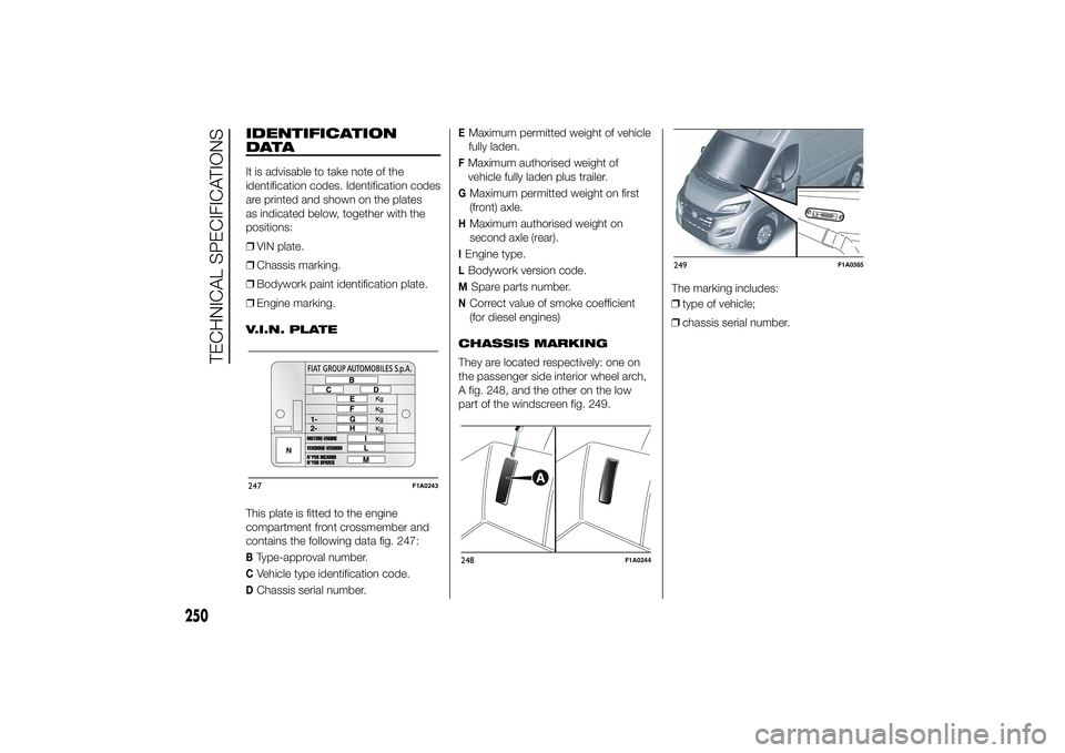
V.I.N. PLATE
This plate is fitted to the engine
compartment front crossmember and
contains the following data fig. 247:BType-approval number.CVehicle type identification code.DChassis serial number.
EMaximum permitted weight of vehicle
fully laden.FMaximum authorised weight of
vehicle fully laden plus trailer.GMaximum permitted weight on first
(front) axle.HMaximum authorised weight on
second axle (rear).IEngine type.LBodywork version code.M
Spare parts number.
NCorrect value of smoke coefficient
(for diesel engines)
CHASSIS MARKING
They are located respectively: one on
the passenger side interior wheel arch,
A fig. 248, and the other on the low
part of the windscreen fig. 249.The marking includes:
❒type of vehicle;
❒chassis serial number.
247
F1A0243
248
F1A0244
249
F1A0365
250
TECHNICAL SPECIFICATIONS