ESC FIAT DUCATO BASE CAMPER 2016 Owner handbook (in English)
[x] Cancel search | Manufacturer: FIAT, Model Year: 2016, Model line: DUCATO BASE CAMPER, Model: FIAT DUCATO BASE CAMPER 2016Pages: 387, PDF Size: 20.76 MB
Page 87 of 387
HILL HOLDER SYSTEM
This system is an integral part of the
ESC system and facilitates starting on
slopes.
It is automatically activated in the
following conditions:
❒uphill: vehicle stationary on a road
with a gradient higher than 5%,
engine running, brake pressed and
gearbox in neutral or gear (other than
reverse) engaged;
❒downhill: vehicle stationary on a road
with a gradient higher than 5%,
engine running, brake pressed and
reverse gear engaged.
When setting off, the ESC system
control unit maintains the braking
pressure on the wheels until the torque
necessary for starting is reached, or
in any case for a maximum of 2
seconds, allowing your right foot to be
moved easily from the brake pedal to
the accelerator.
When two seconds have elapsed,
without starting, the system is
automatically deactivated, gradually
releasing the braking pressure. During
this release stage, the typical brake
disengagement noise indicating that the
vehicle is going to move imminently
will be heard.IMPORTANT The Hill Holder system is
not a parking brake; therefore, never
leave the vehicle without having
engaged the handbrake, turned the
engine off and engaged first gear,
so that it is parked in safe conditions
(for further information read the
"Parking" paragraph in the "Starting
and driving" chapter).
ASR (AntiSlip
Regulation) SYSTEM
It is an integral part of the ESC system.
It automatically operates in the event
of one or both drive wheels slipping,
loss of grip on wet roads (aquaplaning)
and acceleration on slippery, snowy
or icy roads, etc.
Depending on the slipping conditions,
two different control systems are
activated:
❒if the slipping involves both drive
wheels, the ASR intervenes reducing
the power transmitted by the engine;
❒if the slipping only involves one of the
drive wheels, it intervenes
automatically braking the wheel that
is slipping.
62)
Engagement/ disengagement of the
ASR system
The ASR system switches on
automatically each time the engine is
started.
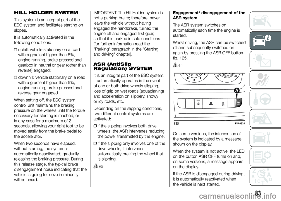
Whilst driving, the ASR can be switched
off and subsequently switched on
again by pressing the ASR OFF button
fig. 125.
61)
On some versions, the intervention of
the system is indicated by a message
shown on the display.
When the system is not active, the LED
on the button ASR OFF turns on and,
on some versions, a message appears
on the display.
If the ASR is disengaged during driving,
it is automatically reactivated when
the vehicle is next started.
125F1A0324
83
Page 88 of 387
When travelling on snowy roads with
snow chains, it may be helpful to turn
the ASR off: in fact, in these conditions,
the driving wheels slipping when
moving off gives you better traction.
HBA SYSTEM
(Hydraulic Brake Assist)
The HBA system is designed to
improve the vehicle’s braking capacity
during emergency braking. The system
detects emergency braking by
monitoring the speed and strength with
which the brake pedal is pressed,
thereby applying the optimal brake
pressure.
This can reduce the braking distance:
the HBA system therefore completes
the ABS.
Maximum assistance from the HBA
system is obtained by pressing the
brake pedal very quickly. In addition,
the brake pedal must be pressed
continuously during braking, avoiding
intermittent presses, to benefit from the
system.
Do not reduce pressure on the brake
pedal until braking is not necessary
anymore.
The HBA system is deactivated when
the brake pedal is released.
63) 64) 65)
ERM ELECTRONIC ROLLOVER
MITIGATION SYSTEM
(Electronic Rollover Mitigation)
The system monitors the tendency of
the wheels to rise from the ground if the
driver performs extreme manoeuvres
like quick steering to avoid an obstacle,
especially in poor road conditions.
If these conditions occur, the system
intervenes on the brakes and engine
power to reduce the possibility that the
wheels are raised from the ground.
It is not possible to avoid the tendency
to roll over if this is due to reasons
such as driving on high side gradients,
collision with objects or other vehicles.
66)
HILL DESCENT CONTROL
(HDC) SYSTEM
It is an integral part of the ESC and is
aimed at keeping the vehicle at a
constant speed during a descent,
operating autonomously on the brakes
in various ways at the same time. In this
way the vehicle stability and completely
safe driving are guaranteed, above all
in poor grip conditions and/or steep
descents.
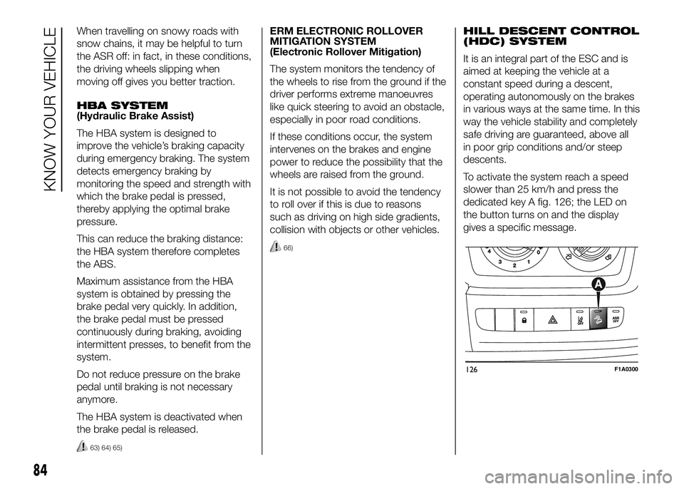
To activate the system reach a speed
slower than 25 km/h and press the
dedicated key A fig. 126; the LED on
the button turns on and the display
gives a specific message.
126F1A0300
84
KNOW YOUR VEHICLE
Page 89 of 387
After reaching the desired speed,
release the accelerator and brake
pedals completely (the LED on the
button flashes). If you want to
increase/decrease the speed, press the
accelerator/brake pedals again.
IMPORTANT Do not use the device
with the gearbox in neutral position.
IMPORTANT It is important to engage a
gear suitable for the set speed, to
prevent the engine from stalling.
When this function is active the brake
lights turn on automatically.
While the HDC system is operating it is
also possible to take control of the
vehicle again by pressing the brake and
accelerator pedals.
If the function is not made available
when the button is pressed, this could
be due to brake overheating. In this
case, wait a few minutes before using
the function again.
IMPORTANT The system is available for
speeds below 25 km/h.IMPORTANT Above 25 km/h the HDC
system deactivates but is still ready
to operate (the LED on the button
remains on) when the speed is again
below 25 km/h. If the speed exceeds
50 km/h, the HDC system deactivates
completely (the LED on the button
switches off) and the function does not
operate autonomously on the brakes
anymore. To reactivate it, press the
dedicated button again when the speed
is again below 25 km/h.
8)
WARNING
58) The ESC system can’t overrule
the natural laws of physics, and
can’t increase the grip available
according to the condition of
the road.
59) The ESC system cannot prevent
accidents, including those due to
excessive speed on corners,
driving on low-grip surfaces or
aquaplaning.60) The capability of the ESC system
must never be tested irresponsibly
and dangerously, in such a way
as to compromise personal safety
and the safety of others.
61) The performance of the ESC and
ASR systems must not encourage
the driver to take unnecessary
risks. Driving style must always be
adapted to road conditions,
visibility and traffic. The driver is,
in any case, responsible for safe
driving.
62) For the ESC and ASR systems to
function correctly, all four tyres
must be the same brand and type,
must be in excellent condition
and, above all, must be of the
prescribed type and size.
63) The HBA system cannot increase
tyre grip on the road over the
limits imposed by laws of physics:
always drive carefully according
to the conditions of the road
surface.
64) The HBA system cannot prevent
accidents, including those due to
excessive speed on bends,
travelling on low-grip surfaces or
aquaplaning.
85
Page 91 of 387
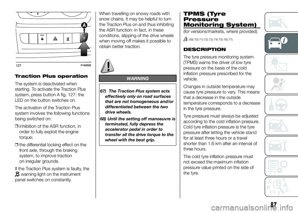
Traction Plus operation
The system is deactivated when
starting. To activate the Traction Plus
system, press button A fig. 127: the
LED on the button switches on.
The activation of the Traction Plus
system involves the following functions
being switched on:
❒inhibition of the ASR function, in
order to fully exploit the engine
torque;
❒the differential locking effect on the
front axle, through the braking
system, to improve traction
on irregular grounds.
If the Traction Plus system is faulty, the
warning light on the instrument
panel switches on constantly.When travelling on snowy roads with
snow chains, it may be helpful to turn
the Traction Plus on and thus inhibiting
the ASR function: in fact, in these
conditions, slipping of the drive wheels
when moving off makes it possible to
obtain better traction.
WARNING
67) The Traction Plus system acts
effectively only on road surfaces
that are not homogeneous and/or
differentiated between the two
drive wheels.
68) Until the setting off manoeuvre is
terminated, fully depress the
accelerator pedal in order to
transfer all the drive torque to the
wheel with the best grip.
TPMS (Tyre
Pressure
Monitoring System)
(for versions/markets, where provided)
69) 70) 71) 72) 73) 74) 75) 76) 77)
DESCRIPTION
The tyre pressure monitoring system
(TPMS) warns the driver of low tyre
pressure on the basis of the cold
inflation pressure prescribed for the
vehicle.
Changes in outside temperature may
cause tyre pressure to vary. This means
that a decrease in the outside
temperature corresponds to a decrease
in the tyre pressure.
Tyre pressure must always be adjusted
according to the cold inflation pressure.
Cold tyre inflation pressure is the tyre
pressure after letting the vehicle stand
for at least three hours or a travel
shorter than 1.6 km after an interval of
three hours.
The cold tyre inflation pressure must
not exceed the maximum inflation
pressure value printed on the side of
the tyre.
127F1A0325
87
Page 92 of 387
The tyre pressure also increases while
driving the vehicle: this is a normal
condition and does not require any
adjustment of the pressure.
The TPMS continues to advise the
driver of the low tyre pressure condition
until this is corrected; the warning
continues until the pressure
corresponds or exceeds the pressure
prescribed for the cold tyres. When the
tyre low pressure control warning
light
switches on constantly, the
inflation pressure must be adjusted until
it reaches the pressure prescribed for
cold tyres. After the automatic update
of the system, the tyre pressure control
warning light switches off. You may
need to drive the vehicle for about 20
minutes at a speed higher than 20
km/h to allow the TPMS to receive this
information.
NOTE
❒The TPMS does not replace the
normal tyre maintenance service and
does not indicate any fault in a tyre.
❒Therefore, the TPMS should not be
used as pressure switch while
adjusting the tyre inflation pressure.❒Driving with insufficient tyre pressure
causes their overheating and can
result in tyre failure. The low inflation
pressure reduces fuel efficiency
and tyre tread life and may also affect
handling and braking performance
of the vehicle.
❒The TPMS does not replace the
correct tyre maintenance. It is up to
the driver to maintain the correct tyre
pressure level measuring it with a
suitable pressure switch. This is
necessary even if the decrease in the
inflation pressure value does not
cause the tyre pressure control
warning light to switch on.
❒The TPMS warns the driver of any
condition of insufficient tyre pressure
If this drops below the insufficient
pressure limit for any reason including
low temperature and normal
pressure loss of the tyre.
❒The seasonal temperature changes
affect tyre pressure.
The TPMS uses wireless devices with
electronic sensors mounted on the
wheel rims to constantly monitor the
value of tyre pressure. The sensors
mounted on each wheel as part of the
valve stem transmit various information
of the tyres to the receiver module, in
order to calculate the pressure.WARNING Monitoring and maintaining
the correct pressure in all four tyres
are particularly important.
Tyre pressure
monitoring system low
pressure warnings
The system warns the driver if one or
more tyres are flat by switching on
the warning light
on the instrument
panel (together with a warning message
and an acoustic signal).
In this case, stop the vehicle as soon as
possible, check the inflation pressure
of each tyre and inflate to the cold tyre
pressure value prescribed for the
vehicle. The system will automatically
update and after receiving the tyre
pressure update the tyre pressure
control warning light switches off. You
may need to drive the vehicle for about
20 minutes at a speed higher than 20
km/h to allow the system to receive this
information.
88
KNOW YOUR VEHICLE
Page 94 of 387
72) Tyre pressure must be checked
with tyres cold. Should it become
necessary for whatever reason
to check pressure with warm
tyres, do not reduce pressure
even if it is higher than the
prescribed value, but repeat the
check when tyres are cold.
73) The TPMS cannot indicate
sudden tyre pressure drops (for
example when a tyre bursts).
In this case, stop the car, braking
with caution and avoiding abrupt
steering.
74) The system only warns that the
tyre pressure is low: it is not able
to inflate them.
75) An insufficient tyre inflation
increases fuel consumption,
reduces the tread duration and
may affect the capacity of driving
safely.
76) Always refit the valve stem cap
after inspecting or adjusting tyre
pressure. This prevents dampness
or dirt from entering the valve
stem and thus the pressure
control sensor from being
damaged.77) The tyre repair kit (Fix&Go)
provided with the car (for
versions/markets, where
provided) is compatible with the
TPMS sensors; using sealants not
equivalent with that in the original
kit may adversely affect its
operation. If sealants not
equivalent with the original one
are used, it is recommended to
have the TPMS sensor operation
checked by a qualified repair
centre.DRIVING ADVISOR
(lane crossing warning)
(for versions/markets, where provided)
82) 79) 80)
The Driving Advisor is a warning system
that notifies the driver if he/she crosses
the lane because he/she has been
distracted.
A video sensor, fitted on the windscreen
near the interior rear view mirror,
detects the lane demarcation lines and
the position of the car in relation to
them.
IMPORTANT On cars with Driving
Advisor, it is advisable to contact a Fiat
Dealership should the windscreen
need to be replaced. If the repair is
carried out at a specialist window
replacement centre, it is still necessary
to go to a Fiat Dealership to have the
camera calibrated.
90
KNOW YOUR VEHICLE
Page 95 of 387
OPERATION
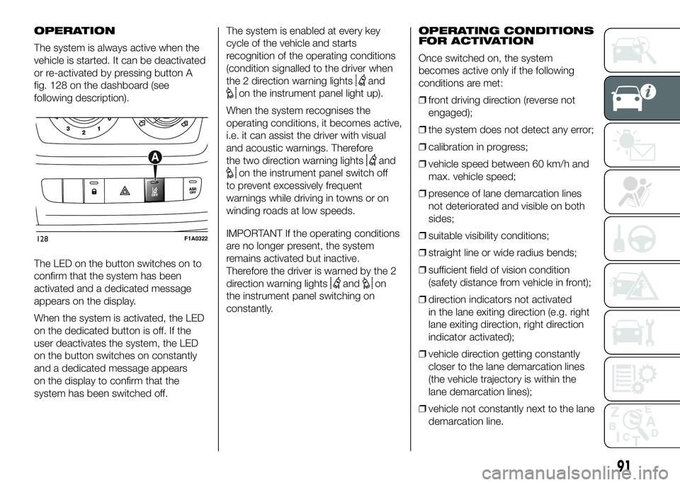
The system is always active when the
vehicle is started. It can be deactivated
or re-activated by pressing button A
fig. 128 on the dashboard (see
following description).
The LED on the button switches on to
confirm that the system has been
activated and a dedicated message
appears on the display.
When the system is activated, the LED
on the dedicated button is off. If the
user deactivates the system, the LED
on the button switches on constantly
and a dedicated message appears
on the display to confirm that the
system has been switched off.The system is enabled at every key
cycle of the vehicle and starts
recognition of the operating conditions
(condition signalled to the driver when
the 2 direction warning lights
and
on the instrument panel light up).
When the system recognises the
operating conditions, it becomes active,
i.e. it can assist the driver with visual
and acoustic warnings. Therefore
the two direction warning lights
and
on the instrument panel switch off
to prevent excessively frequent
warnings while driving in towns or on
winding roads at low speeds.
IMPORTANT If the operating conditions
are no longer present, the system
remains activated but inactive.
Therefore the driver is warned by the 2
direction warning lights
andon
the instrument panel switching on
constantly.OPERATING CONDITIONS
FOR ACTIVATION
Once switched on, the system
becomes active only if the following
conditions are met:
❒front driving direction (reverse not
engaged);
❒the system does not detect any error;
❒calibration in progress;
❒vehicle speed between 60 km/h and
max. vehicle speed;
❒presence of lane demarcation lines
not deteriorated and visible on both
sides;
❒suitable visibility conditions;
❒straight line or wide radius bends;
❒sufficient field of vision condition
(safety distance from vehicle in front);
❒direction indicators not activated
in the lane exiting direction (e.g. right
lane exiting direction, right direction
indicator activated);
❒vehicle direction getting constantly
closer to the lane demarcation lines
(the vehicle trajectory is within the
lane demarcation lines);
❒vehicle not constantly next to the lane
demarcation line.
128F1A0322
91
Page 107 of 387
ENGINE STOPPING
FAILURE CONDITIONS
18)
With the device activated, for reasons
of comfort, limiting emissions and
safety, the engine does not stop in
certain conditions, including:
❒engine still cold;
❒particularly cold external
temperatures, if the corresponding
indication is provided;
❒battery not sufficiently charged;
❒particulate filter regeneration in
progress (diesel engines only);
❒driver's door not shut;
❒driver's seat belt not fastened;
❒reverse gear engaged (for example,
for parking manoeuvres);❒automatic climate control, if a
suitable thermal comfort level has not
yet been reached or MAX-DEF
function activation;
❒during the first period of use, to
initialise the system;
❒if the Hill Descent Control system is
active.
RESTARTING
CONDITIONS
For reasons of comfort, limiting harmful
emissions and safety purposes, the
power unit can restart automatically
without any action by the driver if
certain conditions are met, including:
❒battery not sufficiently charged;
❒reduced braking system vacuum
(e.g. if the brake pedal is pressed
repeatedly);
❒vehicle in motion (e.g. when driving
on roads with a gradient);
❒stopping the engine through the
Start&Stop system for more than
about three minutes.
❒automatic climate control system for
adjusting the thermal comfort level or
to enable MAX-DEF function.
With a gear engaged, the engine can
be automatically restarted only by
fully depressing the clutch pedal.NoteIf the engine stops and this is not
desired, due for example to the clutch
pedal being released sharply with a
gear engaged, if the Start&Stop system
is active, the engine can be restarted
by fully depressing the clutch pedal
or by placing the gear lever in neutral.
NoteIf the clutch is not pressed, when
approx. three minutes have elapsed
since the engine was stopped, the
engine can only be restarted using the
key.
SAFETY FUNCTIONS
In engine cut-out conditions through
the Start&Stop system, if the driver
unfastens his/her seat belt and opens
the driver's door or the passenger door,
the engine can be restarted only by
using the key. The driver is notified of
this condition by a buzzer, through the
warning light flashing in the
instrument panel and, where provided,
by a message in the display.
MODEMODE
133F1A0332
103
Page 108 of 387
"ENERGY SAVING"
FUNCTION
(for versions/markets, where provided)
If, after the engine has been
automatically restarted, the driver does
not take any action for a period of
about 3 minutes, the Start&Stop
system will definitively stop the engine
to avoid fuel consumption. The engine
can only be started using the key in
such cases.
NoteIn any case, it is possible to keep
the engine running by deactivating
the Start&Stop system.
IRREGULAR OPERATION
In the event of malfunction, the
Start&Stop system is deactivated. The
driver is informed about the fault
through the switching on of the
icon
together with a message on the
display. In this case, contact a Fiat
Dealership.VEHICLE INACTIVITY
In the event of vehicle inactivity, special
attention must be paid to the
disconnection of the battery power
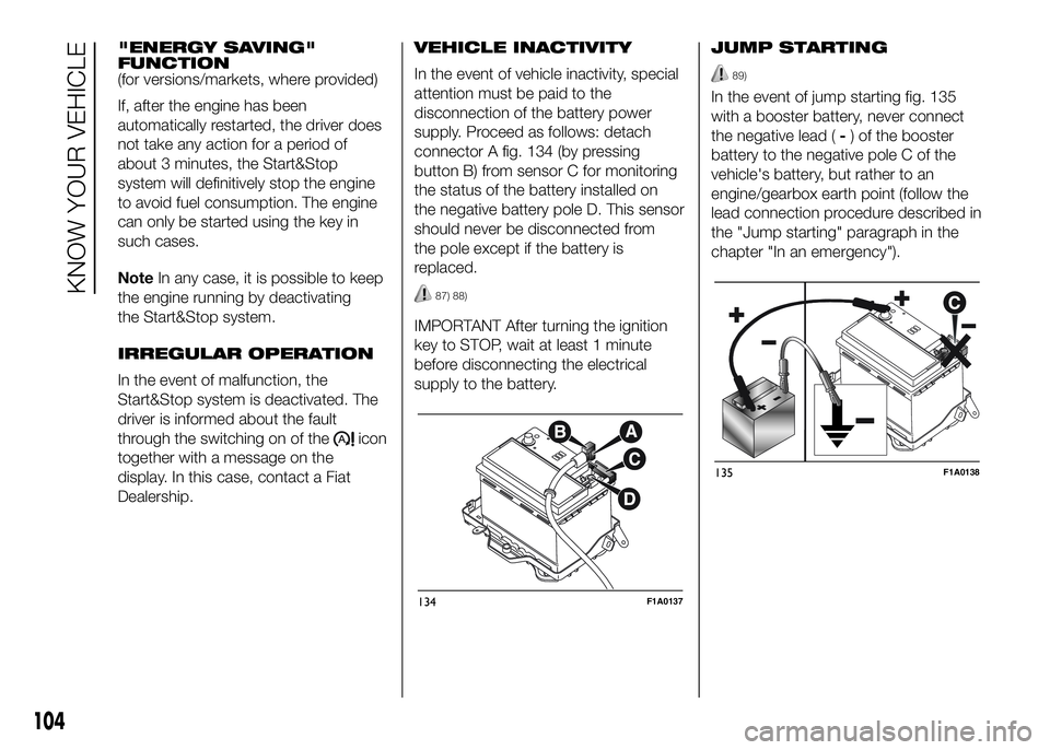
supply. Proceed as follows: detach
connector A fig. 134 (by pressing
button B) from sensor C for monitoring
the status of the battery installed on
the negative battery pole D. This sensor
should never be disconnected from
the pole except if the battery is
replaced.
87) 88)
IMPORTANT After turning the ignition
key to STOP, wait at least 1 minute
before disconnecting the electrical
supply to the battery.JUMP STARTING
89)
In the event of jump starting fig. 135
with a booster battery, never connect
the negative lead (-) of the booster
battery to the negative pole C of the
vehicle's battery, but rather to an
engine/gearbox earth point (follow the
lead connection procedure described in
the "Jump starting" paragraph in the
chapter "In an emergency").
134F1A0137
135F1A0138
104
KNOW YOUR VEHICLE
Page 110 of 387
System description
The vehicle is equipped with an UREA
fuel injection system and a Selective
Catalytic Reduction catalyst to meet the
emission standards.
These two systems ensure compliance
with the diesel emissions requirements;
at the same it maintains fuel saving
levels, driveability, torque and power.
For messages and system warnings
refer to "Knowing the instrument panel"
and "Warning lights and messages".
Remarks
❒When you stop the vehicle you could
hear a distinct click coming from
under the vehicle due to the UREA
injection system, this is normal.
❒The UREA injection system pump
continues to operate for a short
period of time after the engine is
switched off, to purge the circuit. This
is normal, and you can still hear its
noise from under the vehicle.RADIO
(for versions/markets, where provided)
For radio operation, consult the
Supplement attached to this Owner
Handbook.
SETUP
(for versions/markets, where provided)
The system consists of:
❒radio supply leads;
❒front speaker connection cables;
❒aerial supply lead;
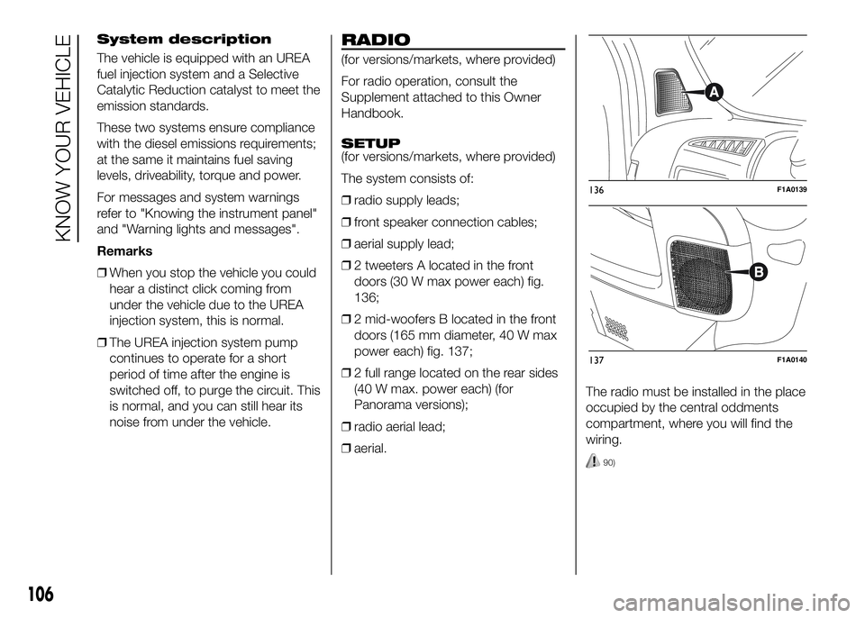
❒2 tweeters A located in the front
doors (30 W max power each) fig.
136;
❒2 mid-woofers B located in the front
doors (165 mm diameter, 40 W max
power each) fig. 137;
❒2 full range located on the rear sides
(40 W max. power each) (for
Panorama versions);
❒radio aerial lead;
❒aerial.The radio must be installed in the place
occupied by the central oddments
compartment, where you will find the
wiring.
90)
136F1A0139
137F1A0140
106
KNOW YOUR VEHICLE