FIAT DUCATO BASE CAMPER 2016 Owner handbook (in English)
Manufacturer: FIAT, Model Year: 2016, Model line: DUCATO BASE CAMPER, Model: FIAT DUCATO BASE CAMPER 2016Pages: 387, PDF Size: 20.76 MB
Page 201 of 387
IMPORTANT
37) The removable ball head bar can
be repaired and disassembled by
the manufacturer only.
38) The supplied plate must be
applied in a visible point on the
vehicle, close to the mounting
pipe or inside the luggage
compartment.
39) Regularly remove all dirt
deposits from the ball head bar
and from the mounting pipe to
ensure a correct system
operation. The mechanical
components must be serviced at
the specified intervals. The lock
must be treated with graphite
only.
40) Periodically lubricate the joints,
the sliding surfaces and the balls
with grease without resin or oil.
Lubrication is also a further
corrosion protection.
41) When the vehicle is cleaned with
high-pressure jets, previously
remove the ball head bar and
insert the suitable plug. The ball
head plug must never be treated
with high-pressure jets.42) Two keys are supplied together
with the removable ball tow bar.
Note down the key number on the
pawl for any following order and
keep it.
197
Removing the tow bar
1. Remove the protection cap from the
lock and press it on the key grip. Open
the lock with the key.
2. Hold the tow bar firmly, remove the
flywheel following the direction of the
arrow and rotate according to the
direction of the arrow b until stopping,
so as to remove till the extracted
position. Then remove the tow bar from
the housing pipe. The flywheel can
then be released; it autonomously
stops in the released position.
3. Arrange the tow bar in the luggage
compartment so that it cannot be
dirtied or damaged by other
transported objects.
4. Insert the suitable plug in the
mounting pipe.
Page 202 of 387
SNOW TYRES
A Fiat Dealership will be happy to
provide advice concerning the most
suitable type of tyre for the customer's
requirements.
The performance of these tyres is
considerably reduced when the tread
depth is less than 4 mm. Replace them
in this case.
Due to the specific characteristics of
snow tyres, in normal weather
conditions or on long motorway
journeys, the performance of these
tyres is lower than that of standard
tyres. Their usage should therefore be
restricted in accordance with their
type approval.
IMPORTANT When using snow tyres
with a maximum speed index below the
one that can be reached by the vehicle
(increased by 5%), place a notice in
the passenger compartment, plainly in
view, which states the maximum speed
allowed by the snow tyres (as per EC
Directive).
All four tyres should be the same (brand
and track) to ensure greater safety
when driving and braking as well as a
good manoeuvrability.
Remember that you should not change
the rotation direction of the tyres.
144)
WARNING
144) The maximum speed for snow
tyres marked "Q" is 160 km/h,
while it is 190 km/h for "T" tyres
and 210 km/h for "H" tyres. You
should, however, always comply
with the speed limits of the
highway code.
SNOW CHAINS
The use of snow chains should be in
compliance with local regulations of
each country.
Snow chains can be fitted to the tyres
of the front wheels (drive wheels) only.
Use of Lineaccessori Fiat snow chains
is recommended. Check the tension
of the snow chains after the first few
metres have been driven.
43)
IMPORTANT With snow chains, use the
accelerator with extreme care to
prevent, or to limit as much as possible,
slipping of the drive wheels that could
cause chain breakage, resulting in
damage to the car body or mechanical
components.
IMPORTANT For versions fitted with
225/75 R16 tyre, use snow chains with
max. thickness 16 mm.
When travelling on snowy roads with
snow chains, it may be helpful to turn
the ASR off: in fact, in these conditions,
the driving wheels skidding when
moving off gives you better traction.
198
STARTING AND DRIVING
Page 203 of 387
IMPORTANT
43) Keep your speed down when
snow chains are fitted; do not
exceed 50 km/h. Avoid potholes,
steps and pavements and avoid
driving for long distances on
roads not covered with snow to
prevent damaging the vehicle and
the roadbed.
PROLONGED
VEHICLE INACTIVITY
If the vehicle needs to be off the road
for longer than one month, the following
precautions must be taken:
❒park the vehicle indoors in a dry and,
if possible, well-ventilated place;
❒engage a gear;
❒check that the handbrake is not
engaged;
❒disconnect the negative battery
terminal; if the vehicle is equipped
with a battery disconnection function
(disconnector), see the description
of the procedure in the "Controls"
paragraph in the "Dashboard and
controls" section;
❒clean and protect the painted parts
using protective wax;
❒clean and protect the shiny metal
parts using special compounds
available commercially;
❒sprinkle talcum powder on the
windscreen and rear window wiper
rubber blades and lift them off the
glass;
❒slightly open the windows;❒cover the vehicle with a piece of
fabric or perforated plastic sheet. Do
not use compact plastic tarpaulins,
which prevent humidity from
evaporating from the surface of the
vehicle;
❒inflate tyres to +0.5 bar above the
standard specified pressure and
check it at intervals;
❒do not drain the engine cooling
system.
IMPORTANT If the vehicle is equipped
with an alarm system, switch off the
vehicle alarm with the remote control.
IMPORTANT After turning the ignition
key to STOP and having closed the
driver side door, wait at least one
minute before disconnecting the
electrical supply from the battery. When
reconnecting the electrical supply to
the battery, make sure that the ignition
key is in the STOP position and the
driver side door is closed.
199
Page 204 of 387
200
This page is intentionally left blank
Page 205 of 387
IN AN EMERGENCY
A punctured tyre or a burnt-out bulb?
At times, a problem may interfere
with our journey.
The pages on emergencies can help
you to deal with critical situations
independently and with calm.
In an emergency we recommend that
you call the freephone number found in
the Warranty Booklet.
It is also possible to call the 00 800
3428 0000 freephone number to
search the nearest Fiat Dealership.STARTING THE ENGINE .................202
REPLACING A WHEEL ...................203
FIX & GO AUTOMATIC QUICK
TYRE REPAIR KIT ...........................208
CHANGING A BULB .......................212
REPLACING AN EXTERIOR BULB ..216
CHANGING AN INTERIOR BULB ....221
REPLACING FUSES........................222
BATTERY RECHARGING ................232
LIFTING THE VEHICLE....................233
TOWING THE VEHICLE ..................233
201
Page 206 of 387
STARTING THE
ENGINE
Go to a Fiat Dealership immediately if
warning light
stays on constantly on
the instrument panel.
JUMP STARTING
If the battery is flat, it is possible to start
the engine using an auxiliary battery
with the same capacity or a little higher
than the flat one.
It is advisable to contact a Fiat
Dealership to check/replace the battery.
145)
Proceed as follows to start the vehicle:
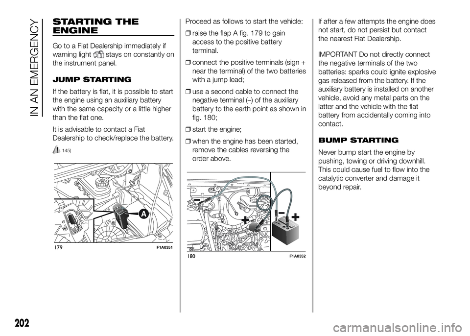
❒raise the flap A fig. 179 to gain
access to the positive battery
terminal.
❒connect the positive terminals (sign +
near the terminal) of the two batteries
with a jump lead;
❒use a second cable to connect the
negative terminal (–) of the auxiliary
battery to the earth point as shown in
fig. 180;
❒start the engine;
❒when the engine has been started,
remove the cables reversing the
order above.If after a few attempts the engine does
not start, do not persist but contact
the nearest Fiat Dealership.
IMPORTANT Do not directly connect
the negative terminals of the two
batteries: sparks could ignite explosive
gas released from the battery. If the
auxiliary battery is installed on another
vehicle, avoid any metal parts on the
latter and the vehicle with the flat
battery from accidentally coming into
contact.
BUMP STARTING
Never bump start the engine by
pushing, towing or driving downhill.
This could cause fuel to flow into the
catalytic converter and damage it
beyond repair.
179F1A0351
180F1A0352
202
IN AN EMERGENCY
Page 207 of 387
WARNING
145) This procedure must be
performed by qualified personnel
as incorrect actions may cause
high-intensity electrical discharge.
Furthermore, battery fluid is
poisonous and corrosive: avoid
contact with skin and eyes. Keep
naked flames and lighted
cigarettes away from the battery
and do not cause sparks.
REPLACING A
WHEEL
GENERAL
INSTRUCTIONS
Wheel replacement and correct use of
the jack and spare wheel (for
versions/markets, where provided) call
for some precautions, which are listed
below.
146) 147) 148) 149) 150)
Please note that:
❒the jack weight is 4.5 kg;
❒the jack requires no adjustment;
❒the jack cannot be repaired: in the
event of a fault it must be replaced by
another original one;
❒no tool other than its cranking device
may be fitted on the jack.
151)
To change a wheel,
proceed as follows:
❒stop the vehicle in a position that is
not dangerous for oncoming traffic
where you can change the wheel
safely. The ground should be flat
if possible, and sufficiently firm;
❒stop the engine and pull the
handbrake;
❒engage first gear or reverse;
❒put on the reflective safety jacket
(compulsory by law in certain
countries) before getting out of the
vehicle;
❒indicate that the vehicle has broken
down using the devices required by
the law in the current country (e.g.
warning triangle, hazard lights, etc.);
❒In the event of a wheel change on a
slope or on unsurfaced roads, put
any object as stop under the wheels;
❒take the tool bag under the
passenger seat (see “Compartment
under front passenger seat” in the
“Know your vehicle” section);
The container includes these tools:
A - tow hook
B - rod for spanner
C - bolt spanner
D - jack
181F1A0168
203
Page 208 of 387
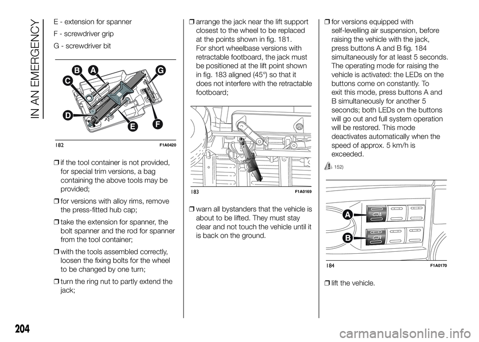
E - extension for spanner
F - screwdriver grip
G - screwdriver bit
❒if the tool container is not provided,
for special trim versions, a bag
containing the above tools may be
provided;
❒for versions with alloy rims, remove
the press-fitted hub cap;
❒take the extension for spanner, the
bolt spanner and the rod for spanner
from the tool container;
❒with the tools assembled correctly,
loosen the fixing bolts for the wheel
to be changed by one turn;
❒turn the ring nut to partly extend the
jack;❒arrange the jack near the lift support
closest to the wheel to be replaced
at the points shown in fig. 181.
For short wheelbase versions with
retractable footboard, the jack must
be positioned at the lift point shown
in fig. 183 aligned (45°) so that it
does not interfere with the retractable
footboard;
❒warn all bystanders that the vehicle is
about to be lifted. They must stay
clear and not touch the vehicle until it
is back on the ground.❒for versions equipped with
self-levelling air suspension, before
raising the vehicle with the jack,
press buttons A and B fig. 184
simultaneously for at least 5 seconds.
The operating mode for raising the
vehicle is activated: the LEDs on the
buttons come on constantly. To
exit this mode, press buttons A and
B simultaneously for another 5
seconds; both LEDs on the buttons
will go out and full system operation
will be restored. This mode
deactivates automatically when the
speed of approx. 5 km/h is
exceeded.
152)
❒lift the vehicle.
182F1A0420
183F1A0169
184F1A0170
204
IN AN EMERGENCY
Page 209 of 387
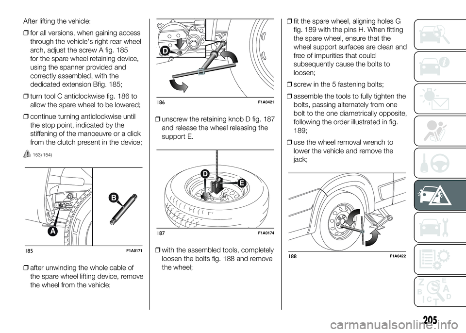
After lifting the vehicle:
❒for all versions, when gaining access
through the vehicle's right rear wheel
arch, adjust the screw A fig. 185
for the spare wheel retaining device,
using the spanner provided and
correctly assembled, with the
dedicated extension Bfig. 185;
❒turn tool C anticlockwise fig. 186 to
allow the spare wheel to be lowered;
❒continue turning anticlockwise until
the stop point, indicated by the
stiffening of the manoeuvre or a click
from the clutch present in the device;
153) 154)
❒after unwinding the whole cable of
the spare wheel lifting device, remove
the wheel from the vehicle;❒unscrew the retaining knob D fig. 187
and release the wheel releasing the
support E.
❒with the assembled tools, completely
loosen the bolts fig. 188 and remove
the wheel;❒fit the spare wheel, aligning holes G
fig. 189 with the pins H. When fitting
the spare wheel, ensure that the
wheel support surfaces are clean and
free of impurities that could
subsequently cause the bolts to
loosen;
❒screw in the 5 fastening bolts;
❒assemble the tools to fully tighten the
bolts, passing alternately from one
bolt to the one diametrically opposite,
following the order illustrated in fig.
189;
❒use the wheel removal wrench to
lower the vehicle and remove the
jack;
185F1A0171
186F1A0421
187F1A0174
188F1A0422
205
Page 210 of 387
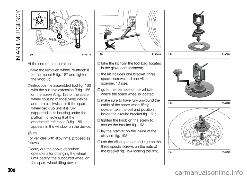
At the end of the operation:
❒take the removed wheel, re-attach it
to the mount E fig. 187 and tighten
the knob D;
❒introduce the assembled tool fig. 186
with the suitable extension B fig. 185
on the screw A fig. 185 of the spare
wheel housing manoeuvring device
and turn clockwise to lift the spare
wheel back up until it is fully
supported in its housing under the
platform, checking that the
attachment reference D fig. 186
appears in the window on the device;
155)
For vehicles with alloy rims, proceed as
follows:
❒carry out the above described
operations for changing the wheel
until loading the punctured wheel on
the spare wheel lifting device;❒take the kit from the tool bag, located
in the glove compartment;
❒the kit includes one bracket, three
special screws and one Allen
spanner, 10 size;
❒go to the rear side of the vehicle
where the spare wheel is located;
❒make sure to have fully unwound the
cable of the spare wheel lifting
device; take the bell and position it
inside the circular bracket fig. 191;
❒tighten the knob on the screw to
secure the bracket fig. 192.
❒lay the bracket on the inside of the
alloy rim fig. 193.
❒use the Allen spanner and tighten the
three special screws on the nuts of
the bracket fig. 194 locking the rim;
G
H
189F1A0176190F1A0430191F1A0424
192F1A0425
193F1A0426
206
IN AN EMERGENCY