FIAT DUCATO BASE CAMPER 2017 Owner handbook (in English)
Manufacturer: FIAT, Model Year: 2017, Model line: DUCATO BASE CAMPER, Model: FIAT DUCATO BASE CAMPER 2017Pages: 296, PDF Size: 14.44 MB
Page 31 of 296
CONTROLS
HAZARD LIGHTS
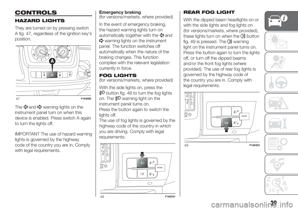
They are turned on by pressing switch
A fig. 47, regardless of the ignition key's
position.
The
andwarning lights on the
instrument panel turn on when this
device is enabled. Press switch A again
to turn the lights off.
IMPORTANT The use of hazard warning
lights is governed by the highway
code of the country you are in. Comply
with legal requirements.Emergency braking
(for versions/markets, where provided)
In the event of emergency braking,
the hazard warning lights turn on
automatically together with the
and
warning lights on the instrument
panel. The function switches off
automatically when the nature of the
braking changes. This function
complies with the relevant legislation
currently in force.
FOG LIGHTS
(for versions/markets, where provided)
With the side lights on, press the
button fig. 48 to turn the fog lights
on. The
warning light on the
instrument panel turns on.
Press the button again to switch the
lights off.
The use of fog lights is governed by the
highway code of the country in which
you are driving. Comply with legal
requirements.REAR FOG LIGHT
With the dipped beam headlights on or
with the side lights and fog lights on
(for versions/markets, where provided),
these lights turn on when the
button
fig. 49 is pressed. The
warning
light on the instrument panel turns on.
Press the button again to turn the lights
off, or turn off the dipped beams
and/or the front fog lights (where
provided). The use of rear fog lights is
governed by the highway code of
the country you are in. Comply with
legal requirements.
47F1A0306
MODE
48F1A0331
MODE
49F1A0323
29
Page 32 of 296
FRONT FOG
LIGHTS/REAR FOG
LIGHTS
(For 2.3 150 ECOJET versions)
With the dipped beam headlights on,
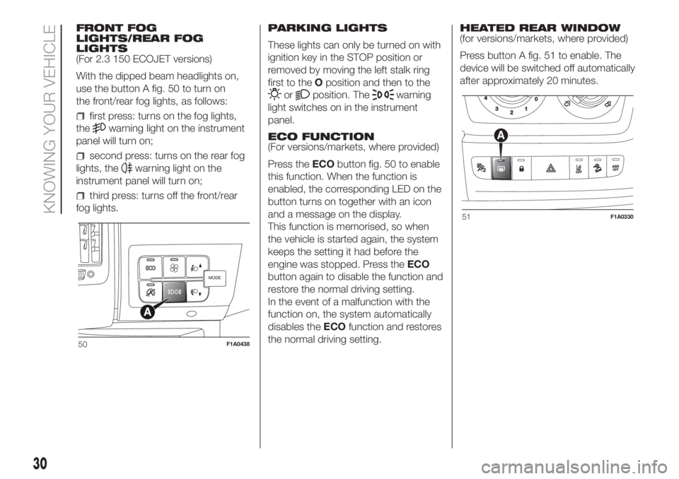
use the button A fig. 50 to turn on
the front/rear fog lights, as follows:
first press: turns on the fog lights,
the
warning light on the instrument
panel will turn on;
second press: turns on the rear fog
lights, the
warning light on the
instrument panel will turn on;
third press: turns off the front/rear
fog lights.PARKING LIGHTS
These lights can only be turned on with
ignition key in the STOP position or
removed by moving the left stalk ring
first to theOposition and then to the
orposition. Thewarning
light switches on in the instrument
panel.
ECO FUNCTION
(For versions/markets, where provided)
Press theECObutton fig. 50 to enable
this function. When the function is
enabled, the corresponding LED on the
button turns on together with an icon
and a message on the display.
This function is memorised, so when
the vehicle is started again, the system
keeps the setting it had before the
engine was stopped. Press theECO
button again to disable the function and
restore the normal driving setting.
In the event of a malfunction with the
function on, the system automatically
disables theECOfunction and restores
the normal driving setting.HEATED REAR WINDOW
(for versions/markets, where provided)
Press button A fig. 51 to enable. The
device will be switched off automatically
after approximately 20 minutes.
MODE
50F1A0438
51F1A0330
30
KNOWING YOUR VEHICLE
Page 33 of 296
BATTERY
DISCONNECTION
FUNCTION
(DISCONNECTOR)
(for versions/markets, where provided)
The battery disconnection function is
enabled with the ignition key in the
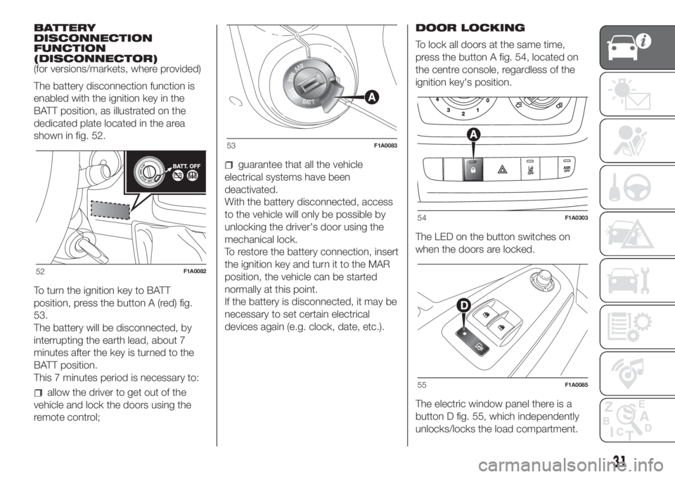
BATT position, as illustrated on the
dedicated plate located in the area
shown in fig. 52.
To turn the ignition key to BATT
position, press the button A (red) fig.
53.
The battery will be disconnected, by
interrupting the earth lead, about 7
BATT position.
This 7 minutes period is necessary to:
allow the driver to get out of the
vehicle and lock the doors using the
remote control;
guarantee that all the vehicle
electrical systems have been
deactivated.
With the battery disconnected, access
to the vehicle will only be possible by
unlocking the driver's door using the
mechanical lock.
To restore the battery connection, insert
the ignition key and turn it to the MAR
position, the vehicle can be started
normally at this point.
If the battery is disconnected, it may be
necessary to set certain electrical
devices again (e.g. clock, date, etc.).DOOR LOCKING
To lock all doors at the same time,
press the button A fig. 54, located on
the centre console, regardless of the
ignition key's position.
The LED on the button switches on
when the doors are locked.
The electric window panel there is a
button D fig. 55, which independently
unlocks/locks the load compartment.
52F1A0082
53F1A0083
54F1A0303
55F1A0085
31
minutes after the key is turned to the
Page 34 of 296
WINDOW WASHING
IN BRIEF
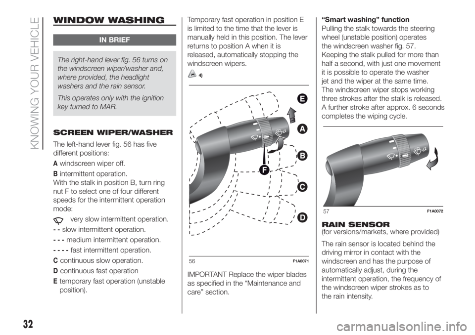
The right-hand lever fig. 56 turns on
the windscreen wiper/washer and,
where provided, the headlight
washers and the rain sensor.
This operates only with the ignition
key turned to MAR.
SCREEN WIPER/WASHER
The left-hand lever fig. 56 has five
different positions:
Awindscreen wiper off.
Bintermittent operation.
With the stalk in position B, turn ring
nut F to select one of four different
speeds for the intermittent operation
mode:
very slow intermittent operation.
--slow intermittent operation.
---medium intermittent operation.
----fast intermittent operation.
Ccontinuous slow operation.
Dcontinuous fast operation
Etemporary fast operation (unstable
position).Temporary fast operation in position E
is limited to the time that the lever is
manually held in this position. The lever
returns to position A when it is
released, automatically stopping the
windscreen wipers.
4)
IMPORTANT Replace the wiper blades
as specified in the “Maintenance and
care” section.“Smart washing” function
Pulling the stalk towards the steering
wheel (unstable position) operates
the windscreen washer fig. 57.
Keeping the stalk pulled for more than
half a second, with just one movement
it is possible to operate the washer
jet and the wiper at the same time.
The windscreen wiper stops working
three strokes after the stalk is released.
A further stroke after approx. 6 seconds
completes the wiping cycle.
RAIN SENSOR
(for versions/markets, where provided)
The rain sensor is located behind the
driving mirror in contact with the
windscreen and has the purpose of
automatically adjust, during the
intermittent operation, the frequency of
the windscreen wiper strokes as to
the rain intensity.
56F1A0071
57F1A0072
32
KNOWING YOUR VEHICLE
Page 35 of 296
IMPORTANT Keep the glass in the
sensor area clean.
Activation fig. 56
Move the right lever down by one click
(position B).
The activation of the sensor is signalled
by a "stroke" to show that the
command has been acquired.
Turn the control F to increase the rain
sensor sensitivity.
The increasing of the rain sensor
sensitivity is signalled by a "stroke" to
show that the command has been
acquired.
If the windscreen washer is used with
the rain sensor activated, the normal
washing cycle is performed, after which
the rain sensor resumes its normal
automatic operation.
Deactivation fig. 56
Move the lever from position B or turn
the ignition key to OFF. The next time
the vehicle is started (ignition key in ON
position), the sensor is not reactivated
even if the lever is still in position B.
To activate the sensor, move the lever
to position A or C and then back to
position B or turn the ring nut for
adjusting the sensitivity. Rain sensor
activation will be indicated by at least
one wiper “stroke” even if the
windscreen is dry.The rain sensor is capable of
recognising the difference between day
and night and making the necessary
adjustments automatically.
33)
HEADLIGHT WASHERS
(for versions/markets, where provided)
The headlight washers are “retractable”,
i.e.: they are located inside the front
bumper and they are activated when
(with dipped beams on) the windscreen
washer is operated.
IMPORTANT Check the correct
condition and cleanliness of nozzles at
regular intervals.
WARNING
33)Streaks of water may cause
unnecessary blade movements.
WARNING
4)Never use the windscreen wiper to
remove layers of snow or ice from
the windscreen. In such conditions, the
windscreen wiper may be subjected to
excessive stress and the motor cut-out
switch, which prevents operation for a few
seconds, may intervene. If operation is
not restored, contact a Fiat Dealership.
33
Page 36 of 296
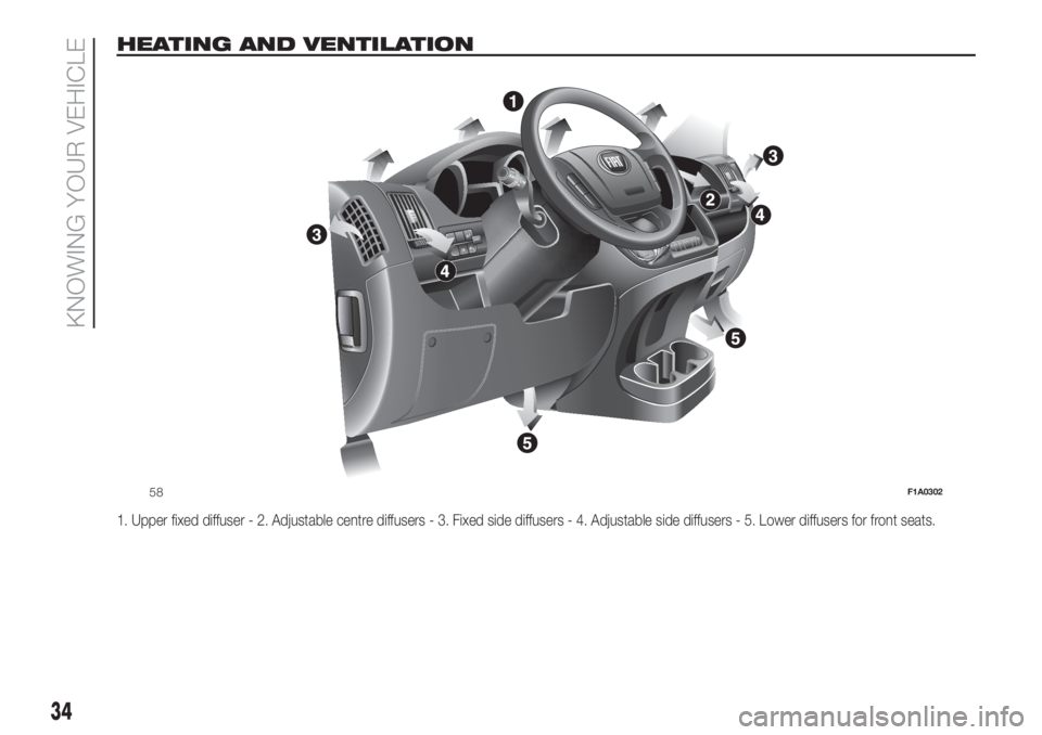
HEATING AND VENTILATION
1. Upper fixed diffuser - 2. Adjustable centre diffusers - 3. Fixed side diffusers - 4. Adjustable side diffusers - 5. Lower diffusers for front seats.
MODE
58F1A0302
34
KNOWING YOUR VEHICLE
Page 37 of 296

HEATING AND
VENTILATION
CONTROLS
CONTROLS
Air temperature adjustment
rotating knob A (mixing hot and
cold air)
Red section = hot air
Blue section = cold air
Knob B activates/adjusts the fan
0 = fan off
1-2-3 = fan speed
4
= maximum fan speedAir distribution ring nut C
to convey air to the central and
side vents;
to warm the feet and convey
slightly cooler air to the dashboard
vents, in intermediate temperature
conditions;
for heating when the outside
temperature is very low: to direct
as much air as possible to the
feet;
to warm the feet and demist the
windscreen at the same time;
for quick windscreen demisting.
Air recirculation on/off knob D
Turn the knob D to
to activate
internal air recirculation.
Turn the knob D to
to deactivate
internal air recirculation.
MANUAL CLIMATE
CONTROL SYSTEM
(for versions/markets, where provided)
2)
CONTROLS
Air temperature adjustment
rotating knob A (mixing hot and
cold air)
Red section = hot air
Blue section = cold air
Knob B activates/adjusts the fan
0 = fan off
1-2-3 = fan speed
4
= maximum fan speed
59F1A0048
60F1A0051
35
Page 38 of 296
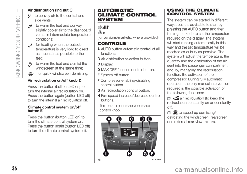
Air distribution ring nut C
to convey air to the central and
side vents;
to warm the feet and convey
slightly cooler air to the dashboard
vents, in intermediate temperature
conditions;
for heating when the outside
temperature is very low: to direct
as much air as possible to the
feet;
to warm the feet and demist the
windscreen at the same time;
for quick windscreen demisting.
Air recirculation on/off knob D
Press the button (button LED on) to
turn the internal air recirculation on.
Press the button again (button LED off)
to turn the internal air recirculation off.
Climate control system on/off
button E
Press the button (button LED on) to
turn the climate control system on.
Press the button again (button LED off)
to turn the climate control system off.
AUTOMATIC
CLIMATE CONTROL
SYSTEM
2)
(for versions/markets, where provided)
CONTROLS
AAUTO button automatic control of all
functions.
BAir distribution selection button.
CDisplay.
DMAX DEF function control button.
ESystem off button.
FCompressor enabling/disabling
control button.
GAir recirculation control button.
HFan speed increase/decrease control
buttons.
ITemperature increase/decrease
control knob.USING THE CLIMATE
CONTROL SYSTEM
The system can be started in different
ways, but it is advisable to start by
pressing the AUTO button and then
turning the knob to set the temperature
required on the display. The system
will start running automatically in this
way and the set temperature will be
reached as quickly as possible. The
system will adjust the temperature, the
quantity and the distribution of the air
sent into the passenger compartment
and, by managing the recirculation
function, the activation of the
compressor. During fully automatic
operation, the only manual intervention
required is the possible activation of
the following functions:
air recirculation (to keep the
recirculation constantly on or constantly
off);
to speed up demisting/
defrosting the windscreen, rearscreen
and external rear-view mirrors.
61F1A0054
36
KNOWING YOUR VEHICLE
Page 39 of 296
During fully automatic system
operation, you can change the set
temperature, air distribution and fan
speed at any time by using the relevant
buttons or knobs: the system will
automatically change its settings to
adjust to the new requirements. During
fully automatic operation (FULL AUTO),
the word FULL will disappear if the air
distribution and/or flow rate and/or
engagement of the compressor and/or
recirculation settings are changed. In
this way, the functions will switch from
automatic to manual control until the
AUTO button is pressed again. With
one or more functions turned on
manually, the adjustment of the intake
air temperature continues to be
managed automatically, except with the
compressor switched off: if this is the
case, the temperature of the air sent
into the passenger compartment
cannot be lower than that of the
outside air.
WARNING
2)The air conditioning system uses R134a
or R1234yf refrigerant compatible with
the regulations in force in the countries
where the vehicle is sold. When charging,
only use the gas indicated on the
dedicated plate in the engine compartment
. The use of other coolants affects the
efficiency and condition of the system. The
lubricant used for the compressor is also
strictly linked to the type of cooling gas,
please refer to a Fiat Dealership.
ADDITIONAL
HEATER
(for versions/markets, where provided)
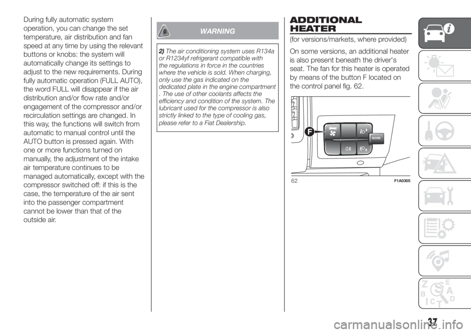
On some versions, an additional heater
is also present beneath the driver's
seat. The fan for this heater is operated
by means of the button F located on
the control panel fig. 62.
MODEF
62F1A0305
37
Page 40 of 296
INDEPENDENT
ADDITIONAL
HEATER
(for versions/markets, where provided)
The vehicle is available, on request,
with two different independent heaters:
one fully automatic, the other which
can be programmed.
AUTOMATIC VERSION
The additional heater is turned on in
automatic mode when the engine
is started and the required outside
temperature and coolant conditions are
present. Deactivation is always
automatic.
34)
IMPORTANT During periods with low
outdoor temperatures when the device
cuts in, check that the fuel level is
always higher than the reserve level.
Otherwise the device could lock and
require the assistance of a Fiat
Dealership.PROGRAMMABLE
VERSION
The additional heater operates
completely independently of engine
operation and allows the following:
heating the passenger compartment
with the engine off
defrosting the windows;
heat the engine coolant and then the
engine itself prior to starting.
The system consists of:
a diesel burner for heating the water
with an exhaust silencer for the
combustion gases;
a metering pump connected to the
reservoir pipes for supplying the burner;
a heat exchanger connected to the
engine cooling system pipes;
a control unit connected to the
passenger compartment heating/
ventilation system to allow automatic
operation;
an electronic control unit for
controlling and adjusting the built-in
burner;
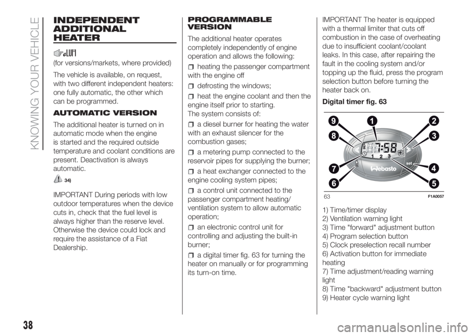
a digital timer fig. 63 for turning the
heater on manually or for programming
its turn-on time.IMPORTANT The heater is equipped
with a thermal limiter that cuts off
combustion in the case of overheating
due to insufficient coolant/coolant
leaks. In this case, after repairing the
fault in the cooling system and/or
topping up the fluid, press the program
selection button before turning the
heater back on.
Digital timer fig. 63
1) Time/timer display
2) Ventilation warning light
3) Time "forward" adjustment button
4) Program selection button
5) Clock preselection recall number
6) Activation button for immediate
heating
7) Time adjustment/reading warning
light
8) Time "backward" adjustment button
9) Heater cycle warning light
63F1A0057
38
KNOWING YOUR VEHICLE