lock FIAT DUCATO BASE CAMPER 2018 Owner handbook (in English)
[x] Cancel search | Manufacturer: FIAT, Model Year: 2018, Model line: DUCATO BASE CAMPER, Model: FIAT DUCATO BASE CAMPER 2018Pages: 304, PDF Size: 14.93 MB
Page 155 of 304

remove the bulb by pushing it
slightly and turning it anticlockwise
(bayonet mount);
refit the bulb holder B by turning it
clockwise and making sure that it locks
correctly
refit the protective rubber cover A
fig. 150.
MAIN BEAM HEADLIGHTSTo replace the bulb, proceed as follows:
remove the protective rubber cover
C fig. 150;
free the bulb holder A fig. 152 from
the side clips B and remove it;
disconnect the electrical connector;
fit the new bulb, ensuring that the
outline of the metal part coincides with
the grooves on the curve of the
headlight, pressing to engage it with the
side clips;
reconnect the electrical connector;
refit the protective rubber cover
C fig. 150.
DIPPED BEAM
HEADLIGHTS
With incandescent bulbs
To replace the bulb, proceed as follows:
remove the protective rubber cover
B fig. 150;
free the bulb holder A fig. 153 from
the side clips B and remove it;
disconnect the electrical connector;
fit the new bulb, ensuring that the
outline of the metal part coincides with
the grooves on the curve of the
headlight, pressing to engage it with the
side clips;
reconnect the electrical connector;
refit the protective rubber cover
B fig. 150.
DIRECTION INDICATORS
To replace the bulb, proceed as follows:
remove the protective rubber cover
A fig. 150;
turn the bulb holder B fig. 154
anticlockwise;
extract the bulb by pulling and
replace it;
remove the bulb by pushing it
slightly and turning it anticlockwise
(bayonet mount);
refit the bulb holder B by turning it
clockwise and making sure that it locks
correctly
refit the protective rubber cover A
fig. 150.
151F1A0386
152F1A0315
153F1A0316
153
Page 156 of 304
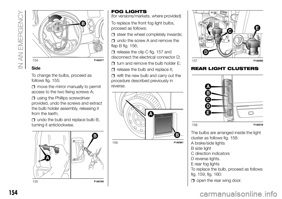
Side
To change the bulbs, proceed as
follows fig. 155:
move the mirror manually to permit
access to the two fixing screws A;
using the Phillips screwdriver
provided, undo the screws and extract
the bulb holder assembly, releasing it
from the teeth;
undo the bulb and replace bulb B,
turning it anticlockwise.FOG LIGHTS
(for versions/markets, where provided)
To replace the front fog light bulbs,
proceed as follows:
steer the wheel completely inwards;
undo the screw A and remove the
flap B fig. 156;
release the clip C fig. 157 and
disconnect the electrical connector D;
turn and remove the bulb holder E;
release the bulb and replace it;
refit the new bulb and carry out the
procedure described previously in
reverse.REAR LIGHT CLUSTERS
The bulbs are arranged inside the light
cluster as follows fig. 158:
A brake/side lights
B side light
C direction indicators
D reverse lights.
E rear fog lights
To replace the bulb, proceed as follows
fig. 159, fig. 160:
open the rear wing door.
154F1A0317
155F1A0195
156F1A0361
157F1A0362
158F1A0318
154
IN AN EMERGENCY
Page 157 of 304

undo the 7 fixing screws A of the
plastic cover;
undo the two fixing screws B;
extract the unit outwards and
disconnect the electrical connector;
unscrew the screws C using the
screwdriver provided and remove the
bulb holder;
remove the bulb D, E, F pushing it
gently and turning it anticlockwise
(“bayonet” locking), then replace it;
remove the bulb G, H pulling outwards;
refit the bulb holder and tighten the
screws C;
reconnect the electrical connector,
correctly reposition the unit on the body
of the vehicle and then tighten the
fixing screws B;
refit the plastic cover fastening it
with the 7 fixing screws A.For truck and chassis cab versions:
Undo the four screws H fig. 161 and
replace the bulbs:
I bulb for rear fog light
L bulb for reversing light
M bulb for side light
N bulb for brake light
O bulb for side light.
159F1A0319160F1A0320
161F1A0200
155
Page 159 of 304
REPLACING
INTERIOR BULBS
For the type of bulb and relevant power
rating, see “Changing a bulb”.
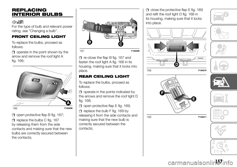
FRONT CEILING LIGHT
To replace the bulbs, proceed as
follows:
operate in the point shown by the
arrow and remove the roof light A
fig. 166;
open protective flap B fig. 167;
replace the bulbs C fig. 167
by releasing them from the side
contacts and making sure that the new
bulbs are correctly secured between
the contacts;
re-close the flap B fig. 167 and
fasten the roof light A fig. 166 in its
housing, making sure that it locks into
place.
REAR CEILING LIGHT
To replace the bulbs, proceed as
follows:
operate in the points indicated by
the arrows and remove the roof light D
fig. 168;
open protective flap E fig. 169;
replace the bulb F fig. 169 by
releasing it from the side contacts and
making sure that the new bulb is
correctly secured between the
contacts;
close the protective flap E fig. 169
and refit the roof light D fig. 168 in
its housing, making sure that it locks
into place.
166F1A0208
167F1A0209
168F1A0210
169F1A0211
157
Page 161 of 304
slowly rotate the screw
anticlockwise until resistance is
encountered (do not overtighten);
slowly release the screw;
opening is indicated by the entire
screw head coming out of its housing;
remove the cover.
To refit the cover proceed as follows:
join the cover with the box correctly;
fully tighten the captive screw using
the dedicated Phillips screwdriver
provided;
slowly rotate the screw clockwise
until resistance is encountered (do not
overtighten);
slowly release the screw;
closure is indicated by the inset of
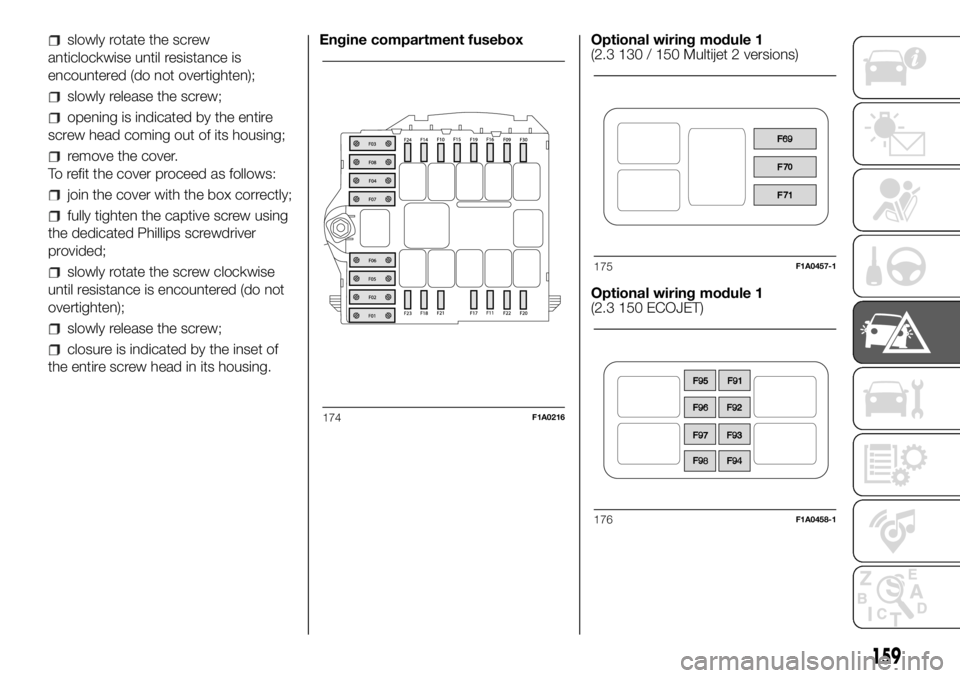
the entire screw head in its housing.Engine compartment fusebox Optional wiring module 1
(2.3 130 / 150 Multijet 2 versions)
Optional wiring module 1
(2.3 150 ECOJET)
174F1A0216
175F1A0457-1
176F1A0458-1
159
Page 163 of 304
Dashboard fusebox
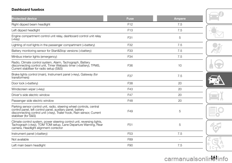
Protected device Fuse Ampere
Right dipped beam headlight F12 7.5
Left dipped headlight F13 7.5
Engine compartment control unit relay, dashboard control unit relay
(+key)F31 5
Lighting of roof lights in the passenger compartment (+battery) F32 7.5
Battery monitoring sensor for Start&Stop versions (+battery) F33 7.5
Minibus interior lights (emergency) F34 7.5
Radio, Climate control system, Alarm, Tachograph, Battery
disconnecting control unit, Timer Webasto timer (+battery), TPMS,
Current stabiliser for radio setup (S&S)F36 10
Brake lights control (main), Instrument panel (+key), Gateway (for
transformers)F37 7.5
Door lock (+battery) F38 20
Windscreen wiper (+key) F43 20
Driver's side electric window F47 20
Passenger side electric window F48 20
Parking sensor control unit, radio, steering wheel controls, central
control panel, left control panel, auxiliary panel, battery
disconnecting control unit (+key), Trailer hook, Rain sensor, Current
stabiliser (for S&S)F49 5
Climate control system, power steering control unit, reversing lights,
Tachograph (+key), TOM TOM setup, Lane Departure Warning, Rear
camera, Headlight alignment correctorF51 5
Instrument panel (+battery) F53 7.5
Not available F89 -
Left main beam headlight F90 7.5
161
Page 176 of 304
Message Signal Description
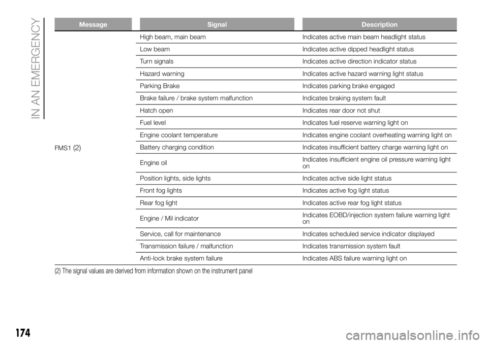
FMS1(2)
High beam, main beam Indicates active main beam headlight status
Low beam Indicates active dipped headlight status
Turn signals Indicates active direction indicator status
Hazard warning Indicates active hazard warning light status
Parking Brake Indicates parking brake engaged
Brake failure / brake system malfunction Indicates braking system fault
Hatch open Indicates rear door not shut
Fuel level Indicates fuel reserve warning light on
Engine coolant temperature Indicates engine coolant overheating warning light on
Battery charging condition Indicates insufficient battery charge warning light on
Engine oilIndicates insufficient engine oil pressure warning light
on
Position lights, side lights Indicates active side light status
Front fog lights Indicates active fog light status
Rear fog light Indicates active rear fog light status
Engine / Mil indicatorIndicates EOBD/injection system failure warning light
on
Service, call for maintenance Indicates scheduled service indicator displayed
Transmission failure / malfunction Indicates transmission system fault
Anti-lock brake system failure Indicates ABS failure warning light on
(2) The signal values are derived from information shown on the instrument panel
174
IN AN EMERGENCY
Page 177 of 304
Message Signal Description
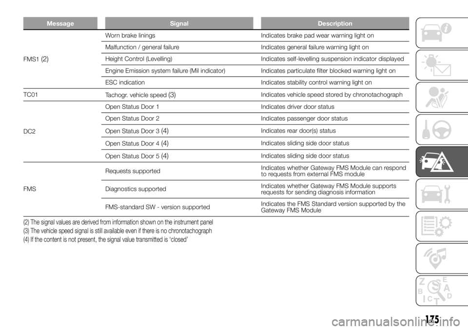
FMS1(2)
Worn brake linings Indicates brake pad wear warning light on
Malfunction / general failure Indicates general failure warning light on
Height Control (Levelling) Indicates self-levelling suspension indicator displayed
Engine Emission system failure (Mil indicator) Indicates particulate filter blocked warning light on
ESC indication Indicates stability control warning light on
TC01
Tachogr. vehicle speed
(3)Indicates vehicle speed stored by chronotachograph
DC2Open Status Door 1 Indicates driver door status
Open Status Door 2 Indicates passenger door status
Open Status Door 3
(4)Indicates rear door(s) status
Open Status Door 4
(4)Indicates sliding side door status
Open Status Door 5
(4)Indicates sliding side door status
FMSRequests supportedIndicates whether Gateway FMS Module can respond
to requests from external FMS module
Diagnostics supportedIndicates whether Gateway FMS Module supports
requests for sending diagnosis information
FMS-standard SW - version supportedIndicates the FMS Standard version supported by the
Gateway FMS Module
(2) The signal values are derived from information shown on the instrument panel
(3) The vehicle speed signal is still available even if there is no chronotachograph
(4) If the content is not present, the signal value transmitted is ‘closed’
175
Page 179 of 304
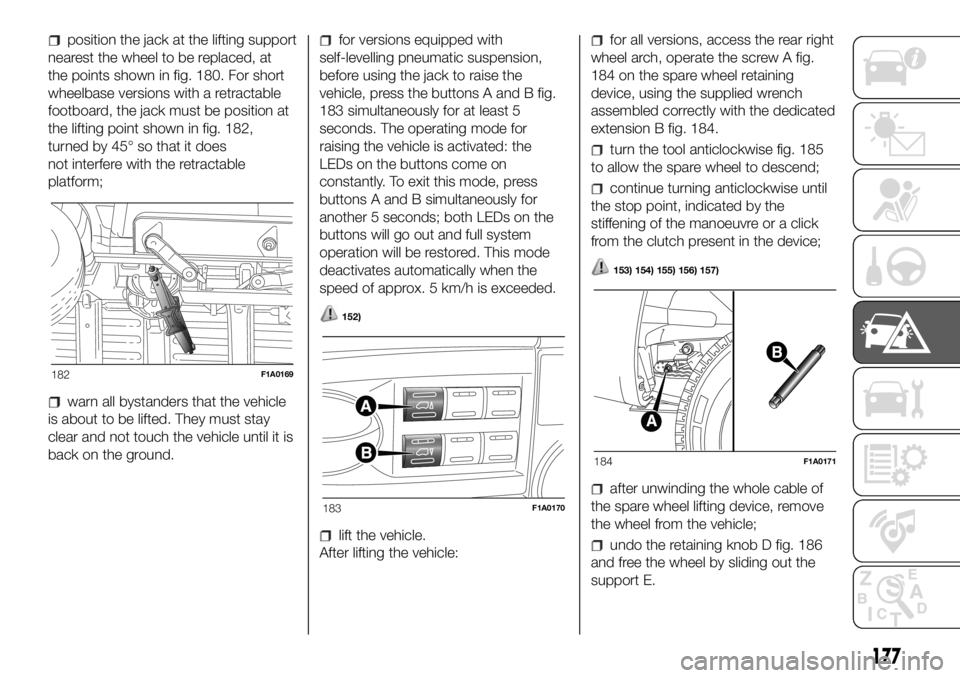
position the jack at the lifting support
nearest the wheel to be replaced, at
the points shown in fig. 180. For short
wheelbase versions with a retractable
footboard, the jack must be position at
the lifting point shown in fig. 182,
turned by 45° so that it does
not interfere with the retractable
platform;
warn all bystanders that the vehicle
is about to be lifted. They must stay
clear and not touch the vehicle until it is
back on the ground.
for versions equipped with
self-levelling pneumatic suspension,
before using the jack to raise the
vehicle, press the buttons A and B fig.
183 simultaneously for at least 5
seconds. The operating mode for
raising the vehicle is activated: the
LEDs on the buttons come on
constantly. To exit this mode, press
buttons A and B simultaneously for
another 5 seconds; both LEDs on the
buttons will go out and full system
operation will be restored. This mode
deactivates automatically when the
speed of approx. 5 km/h is exceeded.
152)
lift the vehicle.
After lifting the vehicle:
for all versions, access the rear right
wheel arch, operate the screw A fig.
184 on the spare wheel retaining
device, using the supplied wrench
assembled correctly with the dedicated
extension B fig. 184.
turn the tool anticlockwise fig. 185
to allow the spare wheel to descend;
continue turning anticlockwise until
the stop point, indicated by the
stiffening of the manoeuvre or a click
from the clutch present in the device;
153) 154) 155) 156) 157)
after unwinding the whole cable of
the spare wheel lifting device, remove
the wheel from the vehicle;
undo the retaining knob D fig. 186
and free the wheel by sliding out the
support E.
182F1A0169
183F1A0170
184F1A0171
177
Page 180 of 304
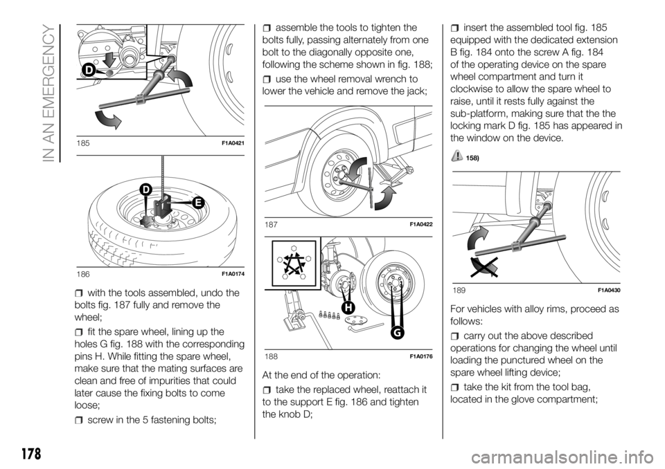
with the tools assembled, undo the
bolts fig. 187 fully and remove the
wheel;
fit the spare wheel, lining up the
holes G fig. 188 with the corresponding
pins H. While fitting the spare wheel,
make sure that the mating surfaces are
clean and free of impurities that could
later cause the fixing bolts to come
loose;
screw in the 5 fastening bolts;
assemble the tools to tighten the
bolts fully, passing alternately from one
bolt to the diagonally opposite one,
following the scheme shown in fig. 188;
use the wheel removal wrench to
lower the vehicle and remove the jack;
At the end of the operation:
take the replaced wheel, reattach it
to the support E fig. 186 and tighten
the knob D;
insert the assembled tool fig. 185
equipped with the dedicated extension
B fig. 184 onto the screw A fig. 184
of the operating device on the spare
wheel compartment and turn it
clockwise to allow the spare wheel to
raise, until it rests fully against the
sub-platform, making sure that the the
locking mark D fig. 185 has appeared in
the window on the device.
158)
For vehicles with alloy rims, proceed as
follows:
carry out the above described
operations for changing the wheel until
loading the punctured wheel on the
spare wheel lifting device;
take the kit from the tool bag,
located in the glove compartment;
185F1A0421
186F1A0174
187F1A0422
G
H
188F1A0176
189F1A0430
178
IN AN EMERGENCY