lock FIAT DUCATO BASE CAMPER 2018 Owner handbook (in English)
[x] Cancel search | Manufacturer: FIAT, Model Year: 2018, Model line: DUCATO BASE CAMPER, Model: FIAT DUCATO BASE CAMPER 2018Pages: 304, PDF Size: 14.93 MB
Page 24 of 304
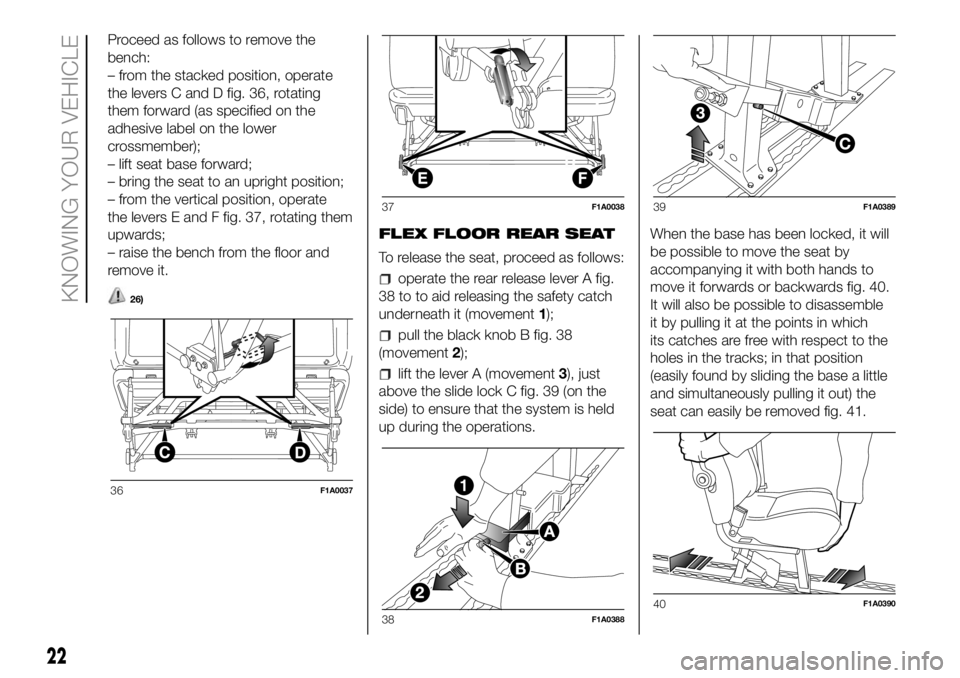
Proceed as follows to remove the
bench:
– from the stacked position, operate
the levers C and D fig. 36, rotating
them forward (as specified on the
adhesive label on the lower
crossmember);
– lift seat base forward;
– bring the seat to an upright position;
– from the vertical position, operate
the levers E and F fig. 37, rotating them
upwards;
– raise the bench from the floor and
remove it.
26)
FLEX FLOOR REAR SEAT
To release the seat, proceed as follows:
operate the rear release lever A fig.
38 to to aid releasing the safety catch
underneath it (movement1);
pull the black knob B fig. 38
(movement2);
lift the lever A (movement3), just
above the slide lock C fig. 39 (on the
side) to ensure that the system is held
up during the operations.When the base has been locked, it will
be possible to move the seat by
accompanying it with both hands to
move it forwards or backwards fig. 40.
It will also be possible to disassemble
it by pulling it at the points in which
its catches are free with respect to the
holes in the tracks; in that position
(easily found by sliding the base a little
and simultaneously pulling it out) the
seat can easily be removed fig. 41.
36F1A0037
37F1A0038
38F1A0388
39F1A0389
40F1A0390
22
KNOWING YOUR VEHICLE
Page 25 of 304
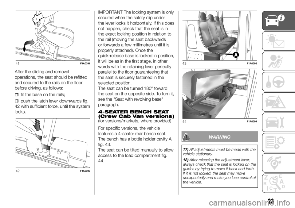
After the sliding and removal
operations, the seat should be refitted
and secured to the rails on the floor
before driving, as follows:
fit the base on the rails;
push the latch lever downwards fig.
42 with sufficient force, until the system
locks.IMPORTANT The locking system is only
secured when the safety clip under
the lever locks it horizontally. If this does
not happen, check that the seat is in
the exact locking position in relation to
the rail (moving the seat backwards
or forwards a few millimetres until it is
properly attached). Once the
quick-release base is locked in position,
it will be as in the first stage, in other
words with the retaining lever perfectly
parallel to the floor guaranteeing that
the seat is securely fastened in the
selected position.
The seat can be turned 180º toward
the seat on the opposite side. To turn it,
see the "Seat with revolving base"
paragraph.
4-SEATER BENCH SEAT
(Crew Cab Van versions)
(for versions/markets, where provided)
For specific versions, the vehicle
features a 4-seater rear bench seat.
The bench has a bottle holder cavity A
fig. 43.
The seat can be tilted manually to allow
access to the load compartment fig.
44.
WARNING
17)All adjustments must be made with the
vehicle stationary.
18)After releasing the adjustment lever,
always check that the seat is locked on the
guides by trying to move it back and forth.
If it is not locked, the seat may move
unexpectedly and make you lose control of
the vehicle.
41F1A0391
42F1A0392
43F1A0393
44F1A0394
23
Page 26 of 304
19)For maximum safety, keep the backrest
upright, lean back into it and make sure
the seat belt fits closely across your chest
and pelvis.
20)Before putting on the seatbelt, ensure
that the armrests are vertical (see
paragraph on "seat belts ”).
21)Before unfastening the belts and
getting out of the vehicle, ensure that the
outer armrest (door side) is fully raised.
22)All adjustments must be made with the
vehicle stationary. In particular, while
turning the seat, take care that it does not
interfere with the handbrake lever.
23)Ensure the seat is locked in driving
position before starting up the vehicle.
24)Do not place heavy loads on the flap
with the vehicle in motion because they
could be thrown against the vehicle
occupants in the event of sudden braking
or impacts, causing severe injury.
25)Do not travel with passengers seated in
the 3rd row with the 2nd row bench folded
over. Do not place objects of any type on
the backrest of the 2nd row bench folded
over: in the event of impact or sharp
braking they could be thrown against the
occupants of the vehicle casing serious
injury. For more information, see the
contents of the adhesive plate located
under the bench.
26)When refitting the bench, ensure that it
is correctly locked to the floor guides.
WARNING
3)The fabric upholstery of your vehicle is
designed to withstand the normal wear
and tear of your vehicle for a long time.
You are however recommended to avoid
strong and/or continuous scratching
with clothing accessories such as metal
buckles, studs, Velcro fastenings and the
like, as these items cause stress of the
cover fabric that could lead to yarn
breaking and damage the upholstery.
STEERING WHEEL
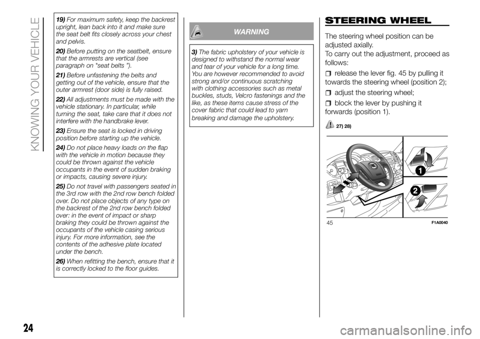
The steering wheel position can be
adjusted axially.
To carry out the adjustment, proceed as
follows:
release the lever fig. 45 by pulling it
towards the steering wheel (position 2);
adjust the steering wheel;
block the lever by pushing it
forwards (position 1).
27) 28)
45F1A0040
24
KNOWING YOUR VEHICLE
Page 33 of 304
FOG LIGHTS ALIGNMENT
(for versions/markets, where provided)
Contact a Fiat Dealership to have the
headlights checked and adjusted.
ADJUSTING THE
HEADLIGHTS WHEN
ABROAD
The dipped beam headlights are
aligned for operation in the country
where the vehicle was originally
purchased. When in countries where
you drive on the other side of the road,
you need to alter the light beam
direction by affixing a specially designed
self-adhesive film in order not to dazzle
the vehicles travelling in the opposite
direction. This film is provided by
Lineaccessori MOPAR and is available
at Fiat Dealerships.
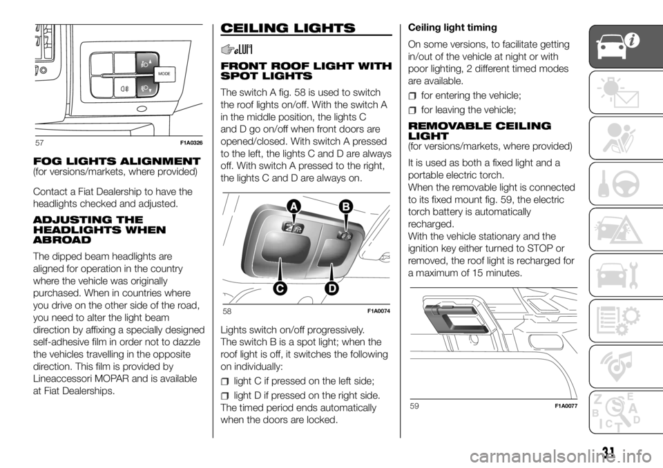
CEILING LIGHTS
FRONT ROOF LIGHT WITH
SPOT LIGHTS
The switch A fig. 58 is used to switch
the roof lights on/off. With the switch A
in the middle position, the lights C
and D go on/off when front doors are
opened/closed. With switch A pressed
to the left, the lights C and D are always
off. With switch A pressed to the right,
the lights C and D are always on.
Lights switch on/off progressively.
The switch B is a spot light; when the
roof light is off, it switches the following
on individually:
light C if pressed on the left side;
light D if pressed on the right side.
The timed period ends automatically
when the doors are locked.Ceiling light timing
On some versions, to facilitate getting
in/out of the vehicle at night or with
poor lighting, 2 different timed modes
are available.
for entering the vehicle;
for leaving the vehicle;
REMOVABLE CEILING
LIGHT
(for versions/markets, where provided)
It is used as both a fixed light and a
portable electric torch.
When the removable light is connected
to its fixed mount fig. 59, the electric
torch battery is automatically
recharged.
With the vehicle stationary and the
ignition key either turned to STOP or
removed, the roof light is recharged for
a maximum of 15 minutes.
MODEMODE
57F1A0326
58F1A0074
59F1A0077
31
Page 35 of 304
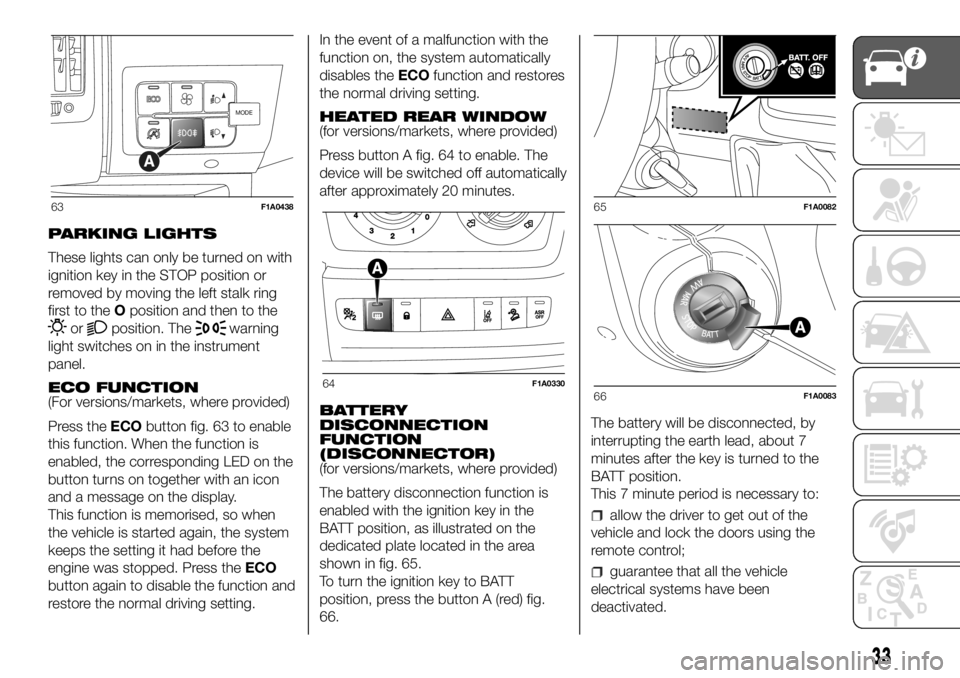
PARKING LIGHTS
These lights can only be turned on with
ignition key in the STOP position or
removed by moving the left stalk ring
first to theOposition and then to the
orposition. Thewarning
light switches on in the instrument
panel.
ECO FUNCTION
(For versions/markets, where provided)
Press theECObutton fig. 63 to enable
this function. When the function is
enabled, the corresponding LED on the
button turns on together with an icon
and a message on the display.
This function is memorised, so when
the vehicle is started again, the system
keeps the setting it had before the
engine was stopped. Press theECO
button again to disable the function and
restore the normal driving setting.In the event of a malfunction with the
function on, the system automatically
disables theECOfunction and restores
the normal driving setting.
HEATED REAR WINDOW
(for versions/markets, where provided)
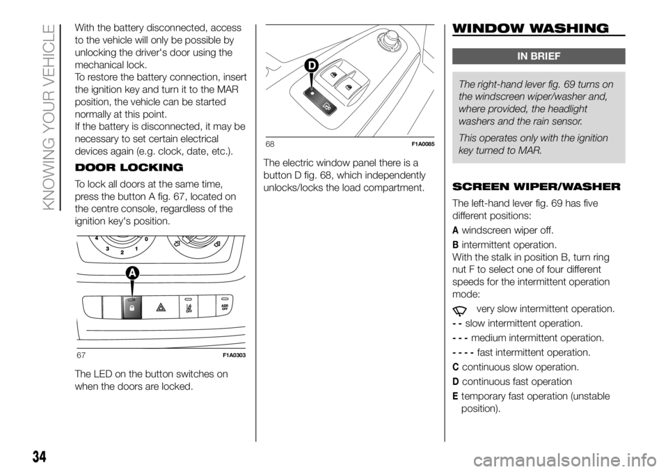
Press button A fig. 64 to enable. The
device will be switched off automatically
after approximately 20 minutes.
BATTERY
DISCONNECTION
FUNCTION
(DISCONNECTOR)
(for versions/markets, where provided)
The battery disconnection function is
enabled with the ignition key in the
BATT position, as illustrated on the
dedicated plate located in the area
shown in fig. 65.
To turn the ignition key to BATT
position, press the button A (red) fig.
66.The battery will be disconnected, by
interrupting the earth lead, about 7
minutes after the key is turned to the
BATT position.
This 7 minute period is necessary to:
allow the driver to get out of the
vehicle and lock the doors using the
remote control;
guarantee that all the vehicle
electrical systems have been
deactivated.
MODE
63F1A0438
64F1A0330
65F1A0082
66F1A0083
33
Page 36 of 304
With the battery disconnected, access
to the vehicle will only be possible by
unlocking the driver's door using the
mechanical lock.
To restore the battery connection, insert
the ignition key and turn it to the MAR
position, the vehicle can be started
normally at this point.
If the battery is disconnected, it may be
necessary to set certain electrical
devices again (e.g. clock, date, etc.).
DOOR LOCKING
To lock all doors at the same time,
press the button A fig. 67, located on
the centre console, regardless of the
ignition key's position.
The LED on the button switches on
when the doors are locked.The electric window panel there is a
button D fig. 68, which independently
unlocks/locks the load compartment.WINDOW WASHING
IN BRIEF
The right-hand lever fig. 69 turns on
the windscreen wiper/washerand,
where provided, the headlight
washers and the rain sensor.
This operates only with the ignition
key turned to MAR.
SCREEN WIPER/WASHER
The left-hand lever fig. 69 has five
different positions:
Awindscreen wiper off.
Bintermittent operation.
With the stalk in position B, turn ring
nut F to select one of four different
speeds for the intermittent operation
mode:
very slow intermittent operation.
--slow intermittent operation.
---medium intermittent operation.
----fast intermittent operation.
Ccontinuous slow operation.
Dcontinuous fast operation
Etemporary fast operation (unstable
position).
67F1A0303
68F1A0085
34
KNOWING YOUR VEHICLE
Page 42 of 304
During fully automatic system
operation, you can change the set
temperature, air distribution and fan
speed at any time by using the relevant
buttons or knobs: the system will
automatically change its settings to
adjust to the new requirements. During
fully automatic operation (FULL AUTO),
the word FULL will disappear if the air
distribution and/or flow rate and/or
engagement of the compressor and/or
recirculation settings are changed. In
this way, the functions will switch from
automatic to manual control until the
AUTO button is pressed again.
WARNING
2)The air conditioning system uses R134a
or R1234yf refrigerant compatible with
the regulations in force in the countries
where the vehicle is sold. When charging,
only use the gas indicated on the
dedicated plate in the engine compartment
. The use of other coolants affects the
efficiency and condition of the system. The
lubricant used for the compressor is also
strictly linked to the type of cooling gas,
please refer to a Fiat Dealership.
ADDITIONAL
HEATER
(for versions/markets, where provided)
On some versions, an additional heater
is also present beneath the driver's
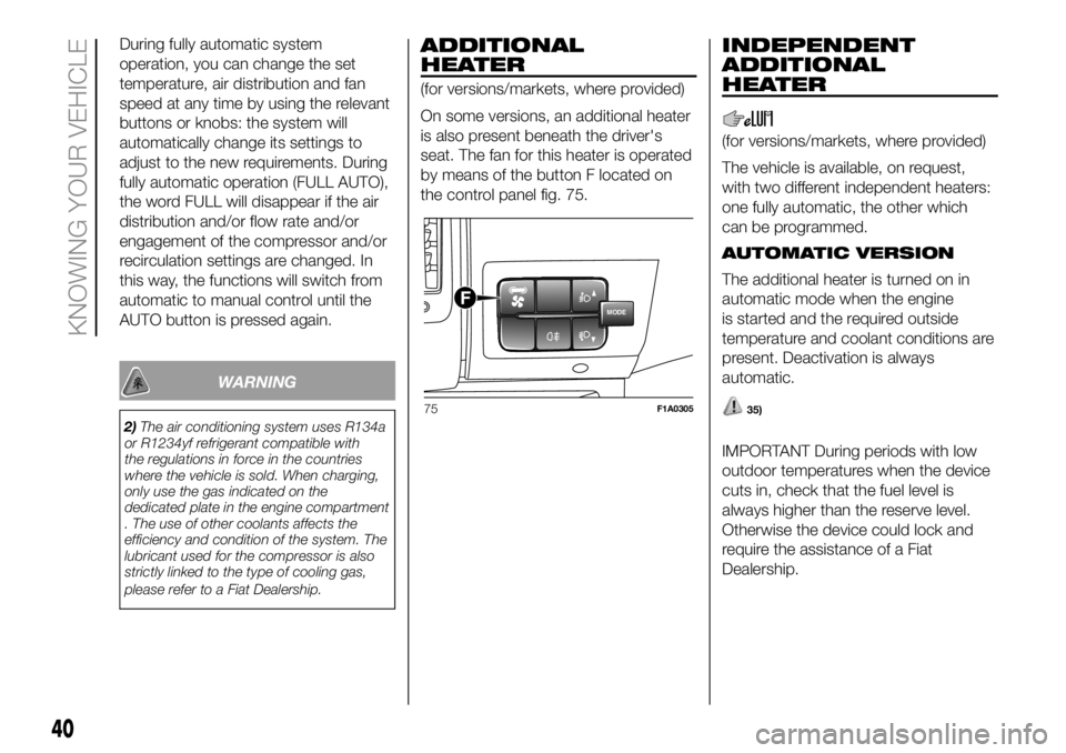
seat. The fan for this heater is operated
by means of the button F located on
the control panel fig. 75.
INDEPENDENT
ADDITIONAL
HEATER
(for versions/markets, where provided)
The vehicle is available, on request,
with two different independent heaters:
one fully automatic, the other which
can be programmed.
AUTOMATIC VERSION
The additional heater is turned on in
automatic mode when the engine
is started and the required outside
temperature and coolant conditions are
present. Deactivation is always
automatic.
35)
IMPORTANT During periods with low
outdoor temperatures when the device
cuts in, check that the fuel level is
always higher than the reserve level.
Otherwise the device could lock and
require the assistance of a Fiat
Dealership.
MODEF
75F1A0305
40
KNOWING YOUR VEHICLE
Page 43 of 304
PROGRAMMABLE
VERSION
The additional heater operates
completely independently of engine
operation and allows the following:
heating the passenger compartment
with the engine off
defrosting the windows;
heat the engine coolant and then the
engine itself prior to starting.
The system consists of:
a diesel burner for heating the water
with an exhaust silencer for the
combustion gases;
a metering pump connected to the
reservoir pipes for supplying the burner;
a heat exchanger connected to the
engine cooling system pipes;
a control unit connected to the
passenger compartment heating/
ventilation system to allow automatic
operation;
an electronic control unit for
controlling and adjusting the built-in
burner;
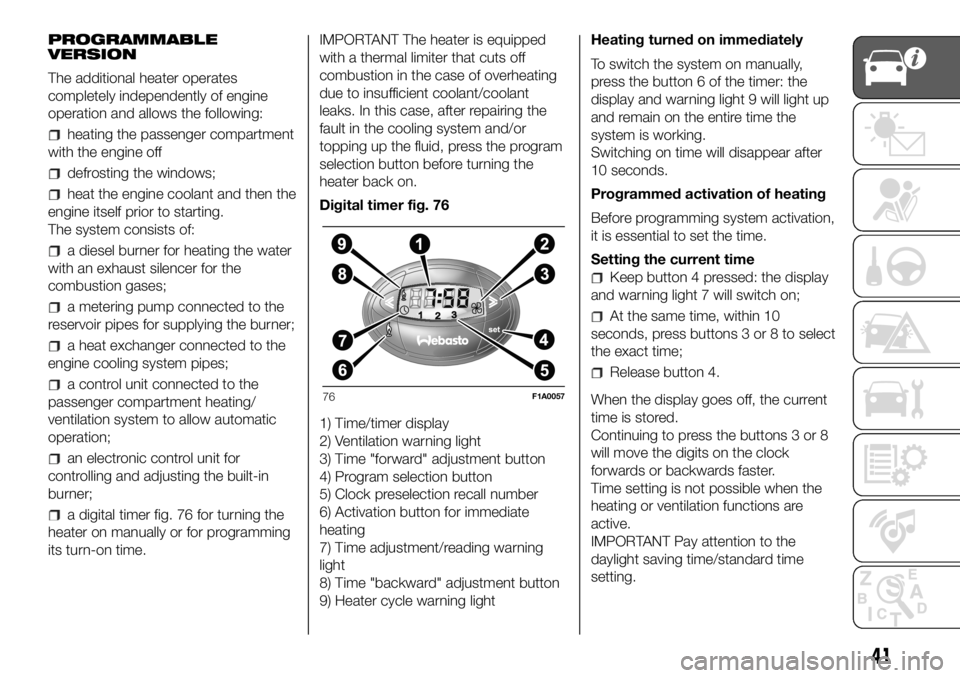
a digital timer fig. 76 for turning the
heater on manually or for programming
its turn-on time.IMPORTANT The heater is equipped
with a thermal limiter that cuts off
combustion in the case of overheating
due to insufficient coolant/coolant
leaks. In this case, after repairing the
fault in the cooling system and/or
topping up the fluid, press the program
selection button before turning the
heater back on.
Digital timer fig. 76
1) Time/timer display
2) Ventilation warning light
3) Time "forward" adjustment button
4) Program selection button
5) Clock preselection recall number
6) Activation button for immediate
heating
7) Time adjustment/reading warning
light
8) Time "backward" adjustment button
9) Heater cycle warning lightHeating turned on immediately
To switch the system on manually,
press the button 6 of the timer: the
display and warning light 9 will light up
and remain on the entire time the
system is working.
Switching on time will disappear after
10 seconds.
Programmed activation of heating
Before programming system activation,
it is essential to set the time.
Setting the current time
Keep button 4 pressed: the display
and warning light 7 will switch on;
At the same time, within 10
seconds, press buttons 3 or 8 to select
the exact time;
Release button 4.
When the display goes off, the current
time is stored.
Continuing to press the buttons 3 or 8
will move the digits on the clock
forwards or backwards faster.
Time setting is not possible when the
heating or ventilation functions are
active.
IMPORTANT Pay attention to the
daylight saving time/standard time
setting.
76F1A0057
41
Page 44 of 304

Programming the switching on time
To program the activation time:
press button 4: the symbol 10 or the
time set previously and the number 5
corresponding to the preselection
recalled will light up in the display for 10
seconds.
IMPORTANT If you wish to recall other
preselected times, press button 4
from time to time within 10 seconds.
– within 10 seconds, press the buttons
3 or 8 to select the desired switching
on time.
IMPORTANT The confirmation that the
time has been memorised is given by:
the disappearance of the switching
on time;
the presence of the preselection
number 5;
the lighting of the display.
IMPORTANT When the boiler comes
on:
the flame warning light 9 switches
on in the display;
the preselection number 5 goes out.
Standard settings:
Preselected time 1: 6:00
Preselected time 2: 16:00
Preselected time 3: 22:00IMPORTANT Factory pre-settings are
cancelled with a new setting.
Preselected times are stored until the
following change. If the clock is
detached from the on-board network
(e.g. if the battery is disconnected), the
factory pre-settings are restored.
Deactivation of the programmed
switching on time
To delete the programmed activation
time, press button 4 briefly: the display
lighting will go off and the number 5
relating to the preselected time will
disappear.
Recalling one of the preselected
switching on times
Operate button 4 within 10 seconds
until the program number with the
desired preselected time is displayed.
The preselected time you have chosen
to set is automatically activated after
about 10 seconds without the need for
any further confirmation with another
button.
Activate the preselected time taking
into account the safety instructions for
the operation of the independent
heating (for this purpose consult the
Owner's Manual for use of independent
heating).IMPORTANT Independent heating
switches on at the preselected time,
both with vehicle parked and while
driving.
IMPORTANT The programmed
switching on time can be altered or
cancelled by following the instructions
given previously.
Operation duration setting
Hold the button pressed. At the same
time press button 3 or 8.
The time and warning light 7 are
displayed.
Press the button 4 again and hold it
down. At the same time press the
button 3 or 8.
The preset activation duration is
displayed and warning light 9 or 2
flashes.
Set the activation duration with button
3or8.
The set activation duration is stored as
soon as the text in the display
disappears, or pressing button 4.
Switching the heating system off
Deactivation of the system, depending
on the type of activation (automatic
or manual), may be:
automaticwhen the programmed
duration is over; when the set time is
over, the display switches off.
42
KNOWING YOUR VEHICLE
Page 45 of 304
manualpressing the “immediate
heating” button on the timer again
(flame button 6).
The heating warning light and the
display light are switched off. The fluid
circulation pump keeps working for
approximately two minutes: the heater
can be switched back on again during
this time.
IMPORTANT The parking heater goes
off when battery voltage is low to allow
the vehicle to be started.
IMPORTANT Before turning on the
device, ensure that the fuel level is
above the reserve. Otherwise the
device could lock and require
the assistance of a Fiat Dealership.
Always turn off the heater when
refuelling and near service stations to
avoid the risk of explosion or fire
hazards.
Do not park the vehicle on
inflammable material such as paper,
grass or dry leaves: fire hazard!
The temperature near the heater
should not exceed 120°C (e.g. during
oven painting in a body shop). The
electronic control unit components may
be damaged at higher temperatures.
Whilst the heater is operating with
the engine switched off, it absorbs
energy from the battery; the engine
should therefore be left running for
a while to make sure that the battery is
properly recharged.
To check the coolant level, follow the
instructions in the "Vehicle
maintenance" chapter, "Engine coolant
system fluid" paragraph. The water in
the heating circuit must contain a
minimum percentage of 10% antifreeze.
For maintenance and repairs,
consult only a Fiat Dealership and use
only original parts.
MAINTENANCE
Have the additional heater checked
regularly at a Fiat Dealership (and
always at the start of every winter). This
will guarantee safe and economic
operation of the heater as well as a long
duration.
ADDITIONAL REAR
HEATING (Panorama and
Combinato)
(for versions/markets, where provided)
The Panorama and Combi versions
are equipped with a main heating
system plus an additional system
(available on request) with controls in
the roof panel trim above the second
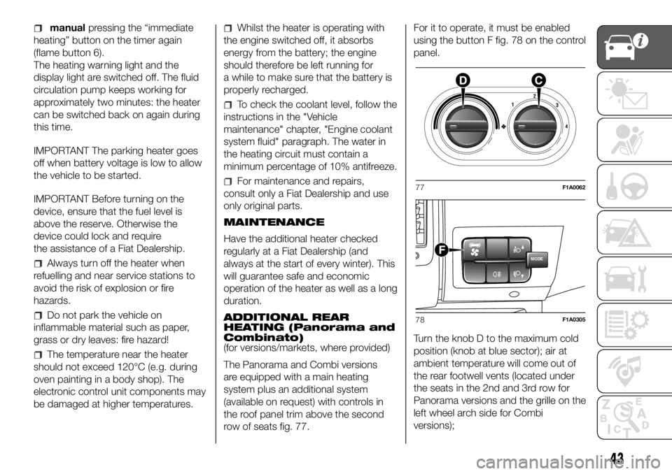
row of seats fig. 77.For it to operate, it must be enabled
using the button F fig. 78 on the control
panel.
Turn the knob D to the maximum cold
position (knob at blue sector); air at
ambient temperature will come out of
the rear footwell vents (located under
the seats in the 2nd and 3rd row for
Panorama versions and the grille on the
left wheel arch side for Combi
versions);77F1A0062
MODEF
78F1A0305
43