seat adjustment FIAT DUCATO BASE CAMPER 2018 Owner handbook (in English)
[x] Cancel search | Manufacturer: FIAT, Model Year: 2018, Model line: DUCATO BASE CAMPER, Model: FIAT DUCATO BASE CAMPER 2018Pages: 304, PDF Size: 14.93 MB
Page 19 of 304
WARNING
2)The footboard presence may reduce the
ramp approach angles; it is therefore
recommended, in case of a very steep
ramp, to be very careful in order not to
damage the footboard.
SEATS
17)
3)
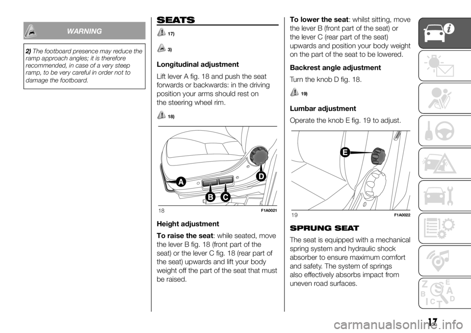
Longitudinal adjustment
Lift lever A fig. 18 and push the seat
forwards or backwards: in the driving
position your arms should rest on
the steering wheel rim.
18)
Height adjustment
To raise the seat: while seated, move
the lever B fig. 18 (front part of the
seat) or the lever C fig. 18 (rear part of
the seat) upwards and lift your body
weight off the part of the seat that must
be raised.To lower the seat: whilst sitting, move
the lever B (front part of the seat) or
the lever C (rear part of the seat)
upwards and position your body weight
on the part of the seat to be lowered.
Backrest angle adjustment
Turn the knob D fig. 18.
19)
Lumbar adjustment
Operate the knob E fig. 19 to adjust.
SPRUNG SEAT
The seat is equipped with a mechanical
spring system and hydraulic shock
absorber to ensure maximum comfort
and safety. The system of springs
also effectively absorbs impact from
uneven road surfaces.
18F1A002119F1A0022
17
Page 20 of 304
See the description in the "Seats"
section for the lengthwise adjustments,
height adjustments, backrest
adjustment, lumbar adjustment and
armrest adjustment.
Ballast weight adjustment
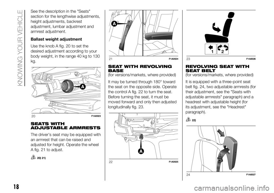
Use the knob A fig. 20 to set the
desired adjustment according to your
body weight, in the range 40 kg to 130
kg.
SEATS WITH
ADJUSTABLE ARMRESTS
The driver's seat may be equipped with
an armrest that can be raised and
adjusted for height. Operate the wheel
A fig. 21 to adjust.
20) 21)
SEAT WITH REVOLVING
BASE
(for versions/markets, where provided)
It may be turned through 180° toward
the seat on the opposite side. Operate
the control A fig. 22 to turn the seat.
Before turning the seat, it must be
moved forward and only then adjusted
longitudinally fig. 23.REVOLVING SEAT WITH
SEAT BELT
(for versions/markets, where provided)
It is equipped with a three-point seat
belt fig. 24, two adjustable armrests (for
their adjustment, see the "Seats with
adjustable armrests" paragraph) and a
headrest with adjustable height (for
its adjustment, see the "Headrest"
paragraph).
22)20F1A0023
21F1A0024
22F1A0025
12
23F1A0026
24F1A0027
18
KNOWING YOUR VEHICLE
Page 21 of 304
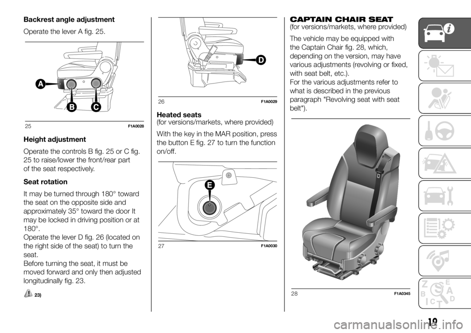
Backrest angle adjustment
Operate the lever A fig. 25.
Height adjustment
Operate the controls B fig. 25 or C fig.
25 to raise/lower the front/rear part
of the seat respectively.
Seat rotation
It may be turned through 180° toward
the seat on the opposite side and
approximately 35° toward the door It
may be locked in driving position or at
180°.
Operate the lever D fig. 26 (located on
the right side of the seat) to turn the
seat.
Before turning the seat, it must be
moved forward and only then adjusted
longitudinally fig. 23.
23)
Heated seats
(for versions/markets, where provided)
With the key in the MAR position, press
the button E fig. 27 to turn the function
on/off.CAPTAIN CHAIR SEAT
(for versions/markets, where provided)
The vehicle may be equipped with
the Captain Chair fig. 28, which,
depending on the version, may have
various adjustments (revolving or fixed,
with seat belt, etc.).
For the various adjustments refer to
what is described in the previous
paragraph "Revolving seat with seat
belt").
25F1A0028
26F1A0029
27F1A0030
28F1A0345
19
Page 23 of 304
PANORAMA VERSIONS
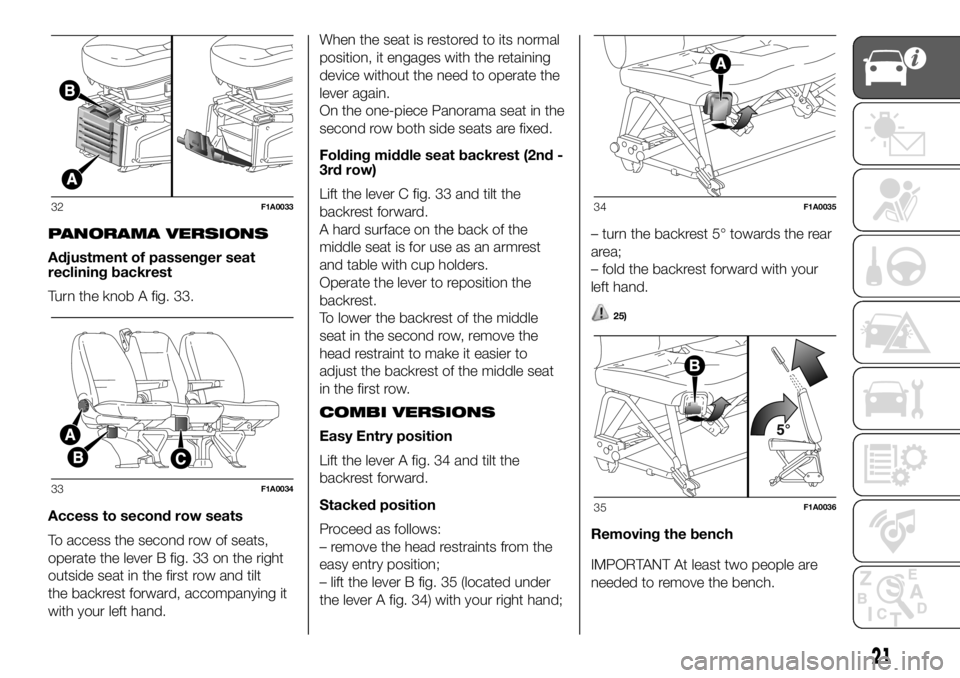
Adjustment of passenger seat
reclining backrest
Turn the knob A fig. 33.
Access to second row seats
To access the second row of seats,
operate the lever B fig. 33 on the right
outside seat in the first row and tilt
the backrest forward, accompanying it
with your left hand.When the seat is restored to its normal
position, it engages with the retaining
device without the need to operate the
lever again.
On the one-piece Panorama seat in the
second row both side seats are fixed.
Folding middle seat backrest (2nd -
3rd row)
Lift the lever C fig. 33 and tilt the
backrest forward.
A hard surface on the back of the
middle seat is for use as an armrest
and table with cup holders.
Operate the lever to reposition the
backrest.
To lower the backrest of the middle
seat in the second row, remove the
head restraint to make it easier to
adjust the backrest of the middle seat
in the first row.
COMBI VERSIONS
Easy Entry position
Lift the lever A fig. 34 and tilt the
backrest forward.
Stacked position
Proceed as follows:
– remove the head restraints from the
easy entry position;
– lift the lever B fig. 35 (located under
the lever A fig. 34) with your right hand;– turn the backrest 5° towards the rear
area;
– fold the backrest forward with your
left hand.
25)
Removing the bench
IMPORTANT At least two people are
needed to remove the bench.
32F1A0033
33F1A0034
34F1A0035
35F1A0036
21
Page 25 of 304
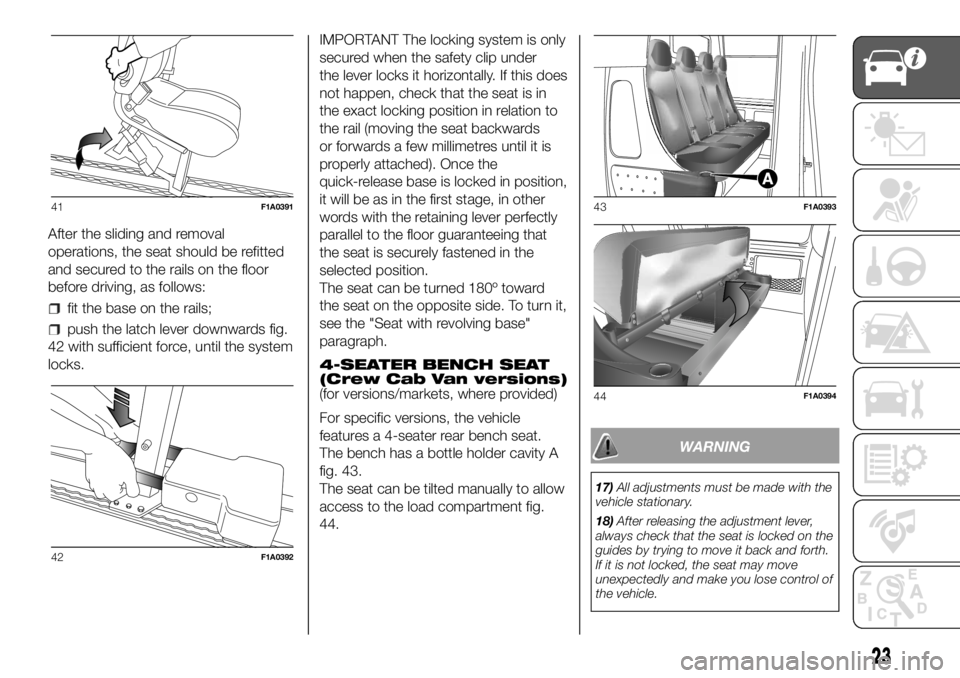
After the sliding and removal
operations, the seat should be refitted
and secured to the rails on the floor
before driving, as follows:
fit the base on the rails;
push the latch lever downwards fig.
42 with sufficient force, until the system
locks.IMPORTANT The locking system is only
secured when the safety clip under
the lever locks it horizontally. If this does
not happen, check that the seat is in
the exact locking position in relation to
the rail (moving the seat backwards
or forwards a few millimetres until it is
properly attached). Once the
quick-release base is locked in position,
it will be as in the first stage, in other
words with the retaining lever perfectly
parallel to the floor guaranteeing that
the seat is securely fastened in the
selected position.
The seat can be turned 180º toward
the seat on the opposite side. To turn it,
see the "Seat with revolving base"
paragraph.
4-SEATER BENCH SEAT
(Crew Cab Van versions)
(for versions/markets, where provided)
For specific versions, the vehicle
features a 4-seater rear bench seat.
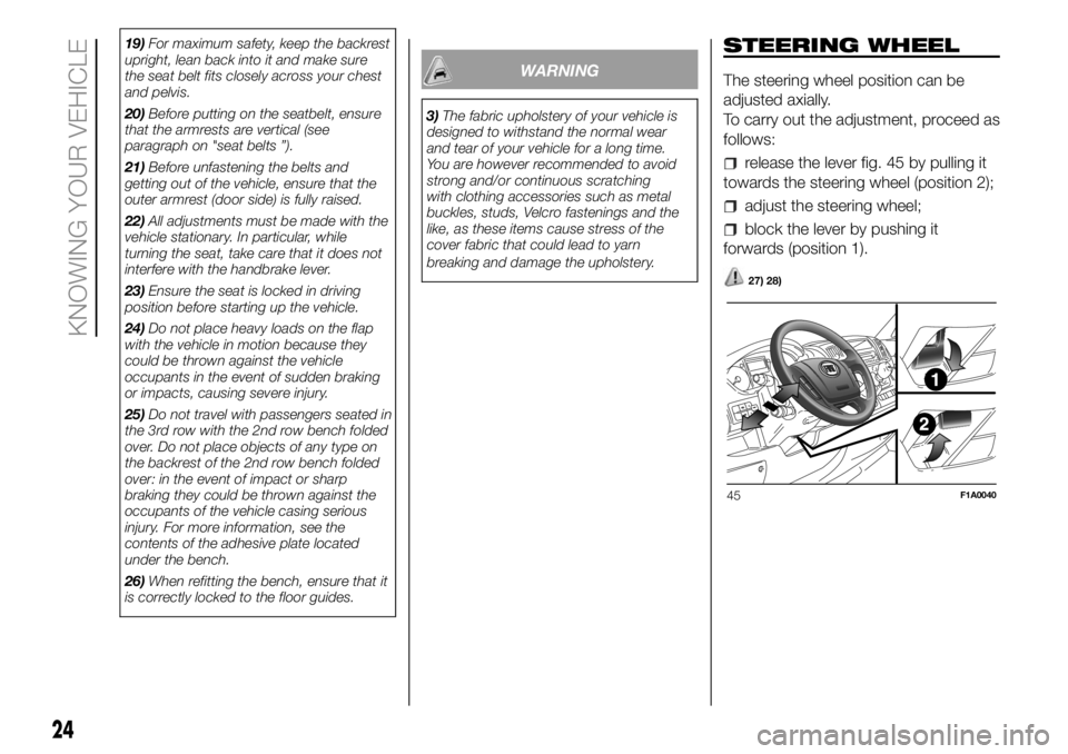
The bench has a bottle holder cavity A
fig. 43.
The seat can be tilted manually to allow
access to the load compartment fig.
44.
WARNING
17)All adjustments must be made with the
vehicle stationary.
18)After releasing the adjustment lever,
always check that the seat is locked on the
guides by trying to move it back and forth.
If it is not locked, the seat may move
unexpectedly and make you lose control of
the vehicle.
41F1A0391
42F1A0392
43F1A0393
44F1A0394
23
Page 26 of 304
19)For maximum safety, keep the backrest
upright, lean back into it and make sure
the seat belt fits closely across your chest
and pelvis.
20)Before putting on the seatbelt, ensure
that the armrests are vertical (see
paragraph on "seat belts ”).
21)Before unfastening the belts and
getting out of the vehicle, ensure that the
outer armrest (door side) is fully raised.
22)All adjustments must be made with the
vehicle stationary. In particular, while
turning the seat, take care that it does not
interfere with the handbrake lever.
23)Ensure the seat is locked in driving
position before starting up the vehicle.
24)Do not place heavy loads on the flap
with the vehicle in motion because they
could be thrown against the vehicle
occupants in the event of sudden braking
or impacts, causing severe injury.
25)Do not travel with passengers seated in
the 3rd row with the 2nd row bench folded
over. Do not place objects of any type on
the backrest of the 2nd row bench folded
over: in the event of impact or sharp
braking they could be thrown against the
occupants of the vehicle casing serious
injury. For more information, see the
contents of the adhesive plate located
under the bench.
26)When refitting the bench, ensure that it
is correctly locked to the floor guides.
WARNING
3)The fabric upholstery of your vehicle is
designed to withstand the normal wear
and tear of your vehicle for a long time.
You are however recommended to avoid
strong and/or continuous scratching
with clothing accessories such as metal
buckles, studs, Velcro fastenings and the
like, as these items cause stress of the
cover fabric that could lead to yarn
breaking and damage the upholstery.
STEERING WHEEL
The steering wheel position can be
adjusted axially.
To carry out the adjustment, proceed as
follows:
release the lever fig. 45 by pulling it
towards the steering wheel (position 2);
adjust the steering wheel;
block the lever by pushing it
forwards (position 1).
27) 28)
45F1A0040
24
KNOWING YOUR VEHICLE
Page 49 of 304
WARNING
40)All adjustments must only be carried
out with the vehicle stationary and the
engine off. Head restraints must be
adjusted so that the head, rather than the
neck, rests on them. Only in this case
can they protect your head correctly. To
take best advantage of the protection
provided by the head restraint, adjust the
seat back so that you are sitting up straight
and your head is as close to the head
restraint as possible.
INTERIOR FITTINGS
COMPARTMENT
BENEATH PASSENGER
SIDE FRONT SEAT
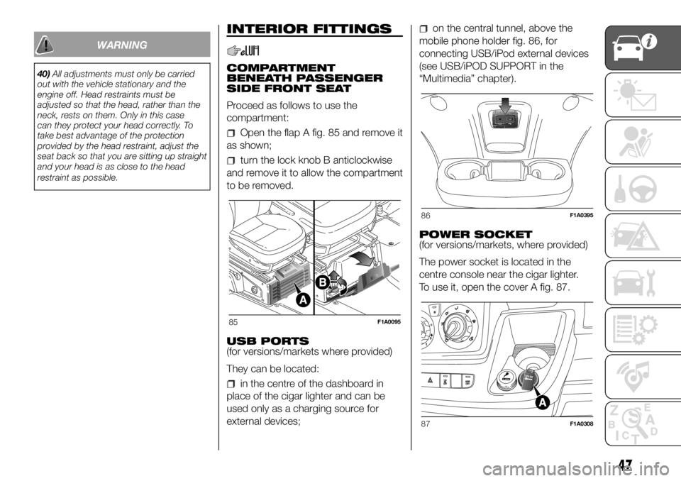
Proceed as follows to use the
compartment:
Open the flap A fig. 85 and remove it
as shown;
turn the lock knob B anticlockwise
and remove it to allow the compartment
to be removed.
USB PORTS
(for versions/markets where provided)
They can be located:
in the centre of the dashboard in
place of the cigar lighter and can be
used only as a charging source for
external devices;
on the central tunnel, above the
mobile phone holder fig. 86, for
connecting USB/iPod external devices
(see USB/iPOD SUPPORT in the
“Multimedia” chapter).
POWER SOCKET
(for versions/markets, where provided)
The power socket is located in the
centre console near the cigar lighter.
To use it, open the cover A fig. 87.
85F1A0095
86F1A0395
87F1A0308
47
Page 99 of 304
SEAT BELTS
IN BRIEF
All the seats in the vehicle are
equipped with seatbelts with three
anchoring points and a retractor. The
reel mechanism operates locking
the belt in the event of sharp braking
or strong deceleration due to an
impact. This allows the belt strap to
slide freely and to adapt to the body
of the occupant. In the event of an
accident, the belt will lock to reduce
the risk of impact inside the
passenger compartment or of being
projected outside the vehicle. The
driver is responsible for respecting,
and ensuring that all the other
occupants of the vehicle also
respect, the local laws in force in
relation to the use of the seat belts.
Always fasten the seat belts before
setting off.
USING THE SEAT BELTS
The belt should be worn keeping the
torso straight and rested against the
backrest.
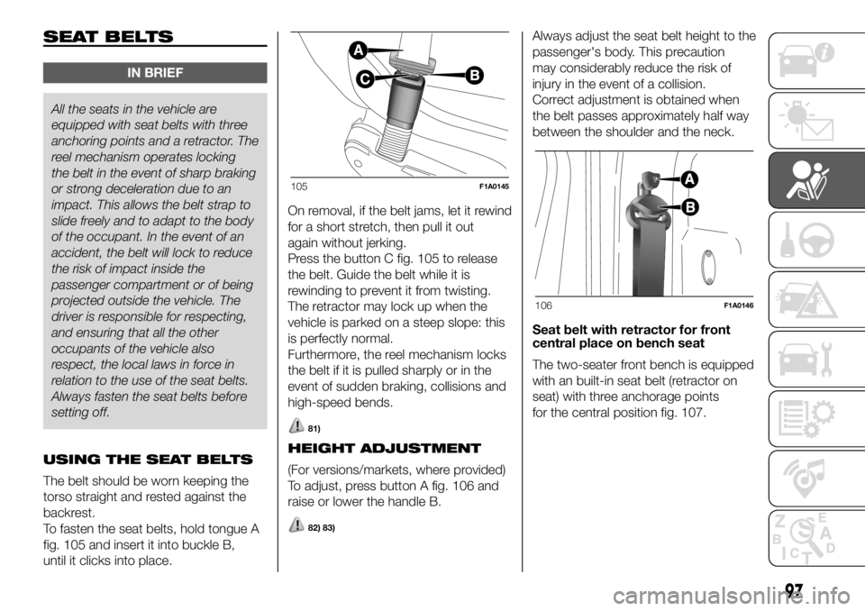
To fasten the seat belts, hold tongue A
fig. 105 and insert it into buckle B,
until it clicks into place.On removal, if the belt jams, let it rewind
for a short stretch, then pull it out
again without jerking.
Press the button C fig. 105 to release
the belt. Guide the belt while it is
rewinding to prevent it from twisting.
The retractor may lock up when the
vehicle is parked on a steep slope: this
is perfectly normal.
Furthermore, the reel mechanism locks
the belt if it is pulled sharply or in the
event of sudden braking, collisions and
high-speed bends.
81)
HEIGHT ADJUSTMENT
(For versions/markets, where provided)
To adjust, press button A fig. 106 and
raise or lower the handle B.
82) 83)
Always adjust the seat belt height to the
passenger's body. This precaution
may considerably reduce the risk of
injury in the event of a collision.
Correct adjustment is obtained when
the belt passes approximately half way
between the shoulder and the neck.
Seat belt with retractor for front
central place on bench seat
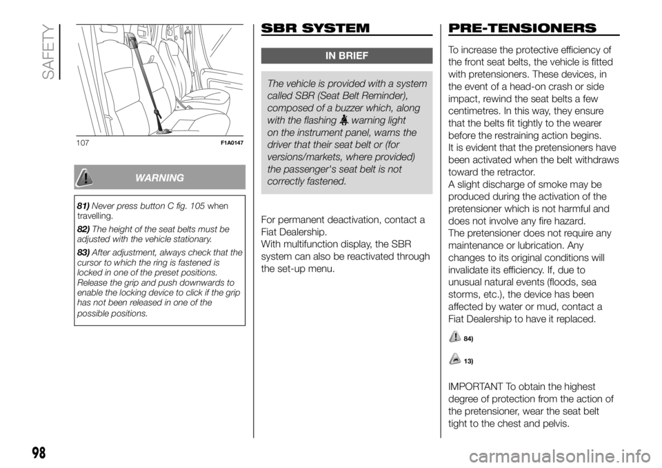
The two-seater front bench is equipped
with an built-in seat belt (retractor on
seat) with three anchorage points
for the central position fig. 107.
105F1A0145
106F1A0146
97
Page 100 of 304
WARNING
81)Never press button C fig. 105when
travelling.
82)The height of the seat belts must be
adjusted with the vehicle stationary.
83)After adjustment, always check that the
cursor to which the ring is fastened is
locked in one of the preset positions.
Release the grip and push downwards to
enable the locking device to click if the grip
has not been released in one of the
possible positions.
SBR SYSTEM
IN BRIEF
The vehicle is provided with a system
called SBR (SeatBelt Reminder),
composed of a buzzer which, along
with the flashing
warning light
on the instrument panel, warns the
driver that their seat belt or (for
versions/markets, where provided)
the passenger's seat belt is not
correctly fastened.
For permanent deactivation, contact a
Fiat Dealership.
With multifunction display, the SBR
system can also be reactivated through
the set-up menu.
PRE-TENSIONERS
To increase the protective efficiency of
the front seat belts, the vehicle is fitted
with pretensioners. These devices, in
the event of a head-on crash or side
impact, rewind the seat belts a few
centimetres. In this way, they ensure
that the belts fit tightly to the wearer
before the restraining action begins.
It is evident that the pretensioners have
been activated when the belt withdraws
toward the retractor.
A slight discharge of smoke may be
produced during the activation of the
pretensioner which is not harmful and
does not involve any fire hazard.
The pretensioner does not require any
maintenance or lubrication. Any
changes to its original conditions will
invalidate its efficiency. If, due to
unusual natural events (floods, sea
storms, etc.), the device has been
affected by water or mud, contact a
Fiat Dealership to have it replaced.
84)
13)
IMPORTANT To obtain the highest
degree of protection from the action of
the pretensioner, wear the seat belt
tight to the chest and pelvis.
107F1A0147
98
SAFETY
Page 178 of 304
CHANGING A WHEEL
GENERAL
INSTRUCTIONS
Wheel replacement and correct use of
the jack and spare wheel (for
versions/markets, where provided) call
for some precautions, which are listed
below.
146) 147) 148) 149) 150)
Please note that:
the jack weight is 4.5 kg;
the jack requires no adjustment;
the jack cannot be repaired: in the
event of a fault it must be replaced
by another original one;
no tool other than its cranking
device may be fitted on the jack.
151)
To change a wheel, proceed as
follows:
stop the vehicle in a position that is
not dangerous for oncoming traffic
where you can change the wheel safely.
The ground must be flat and sufficiently
compact;
switch off the engine and pull the
handbrake;
engage first gear or reverse;
put on the reflective safety jacket
(compulsory by law in certain countries)
before getting out of the vehicle;
indicate that the vehicle has broken
down using the devices required by
the law in the current country (e.g.
warning triangle, hazard lights, etc.);
in the event of a wheel change on a
slope or on unsurfaced roads, put
any object as stop under the wheels;
take the tool bag from under the
passenger seat (see "Compartment
under the front passenger side seat" in
the "Internal equipment" chapter in
"Knowing the vehicle").
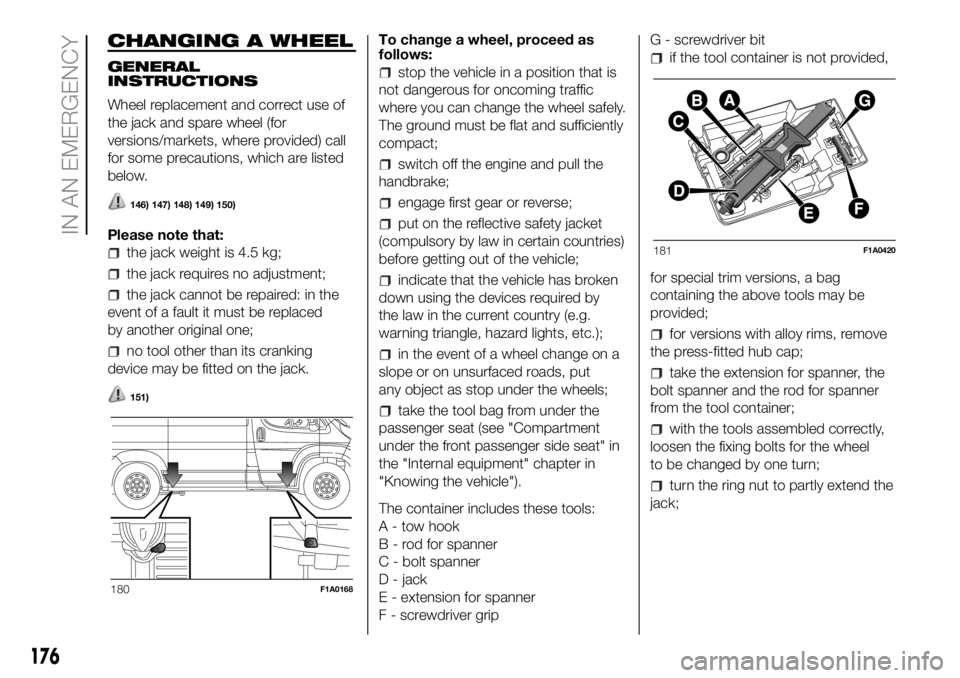
The container includes these tools:
A - tow hook
B - rod for spanner
C - bolt spanner
D - jack
E - extension for spanner
F - screwdriver gripG - screwdriver bit
if the tool container is not provided,
for special trim versions, a bag
containing the above tools may be
provided;
for versions with alloy rims, remove
the press-fitted hub cap;
take the extension for spanner, the
bolt spanner and the rod for spanner
from the tool container;
with the tools assembled correctly,
loosen the fixing bolts for the wheel
to be changed by one turn;
turn the ring nut to partly extend the
jack;
180F1A0168
181F1A0420
176
IN AN EMERGENCY