engine FIAT DUCATO BASE CAMPER 2018 Owner handbook (in English)
[x] Cancel search | Manufacturer: FIAT, Model Year: 2018, Model line: DUCATO BASE CAMPER, Model: FIAT DUCATO BASE CAMPER 2018Pages: 304, PDF Size: 14.93 MB
Page 172 of 304
WARNING
142)Never replace a fuse with another with a higher amp rating; DANGER OF FIRE. If a general protection fuse (MEGA-FUSE, MIDI-FUSE) is
activated, contact a Fiat Dealership.
143)Before replacing a fuse, make sure that the ignition key has been removed and that all the other services are switched off and/or
disengaged.
144)If the replaced fuse blows again, contact a Fiat Dealership.
145)Contact Fiat Dealership if a safety system (airbags, brakes), engine system (engine, gearbox) or steering system general protection fuse
blows.
WARNING
48)Never replace a faulty fuse with metal wires or anything else.
170
IN AN EMERGENCY
Page 174 of 304
Message Signal Description
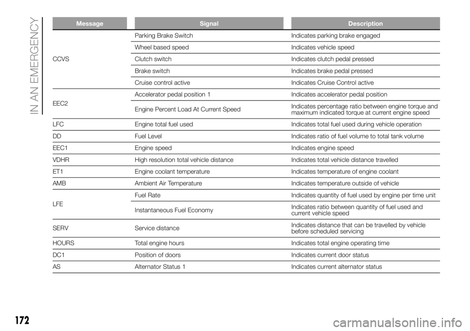
CCVSParking Brake Switch Indicates parking brake engaged
Wheel based speed Indicates vehicle speed
Clutch switch Indicates clutch pedal pressed
Brake switch Indicates brake pedal pressed
Cruise control active Indicates Cruise Control active
EEC2Accelerator pedal position 1 Indicates accelerator pedal position
Engine Percent Load At Current SpeedIndicates percentage ratio between engine torque and
maximum indicated torque at current engine speed
LFC Engine total fuel used Indicates total fuel used during vehicle operation
DD Fuel Level Indicates ratio of fuel volume to total tank volume
EEC1 Engine speed Indicates engine speed
VDHR High resolution total vehicle distance Indicates total vehicle distance travelled
ET1 Engine coolant temperature Indicates temperature of engine coolant
AMB Ambient Air Temperature Indicates temperature outside of vehicle
LFEFuel Rate Indicates quantity of fuel used by engine per time unit
Instantaneous Fuel EconomyIndicates ratio between quantity of fuel used and
current vehicle speed
SERV Service distanceIndicates distance that can be travelled by vehicle
before scheduled servicing
HOURS Total engine hours Indicates total engine operating time
DC1 Position of doors Indicates current door status
AS Alternator Status 1 Indicates current alternator status
172
IN AN EMERGENCY
Page 176 of 304
Message Signal Description
FMS1(2)
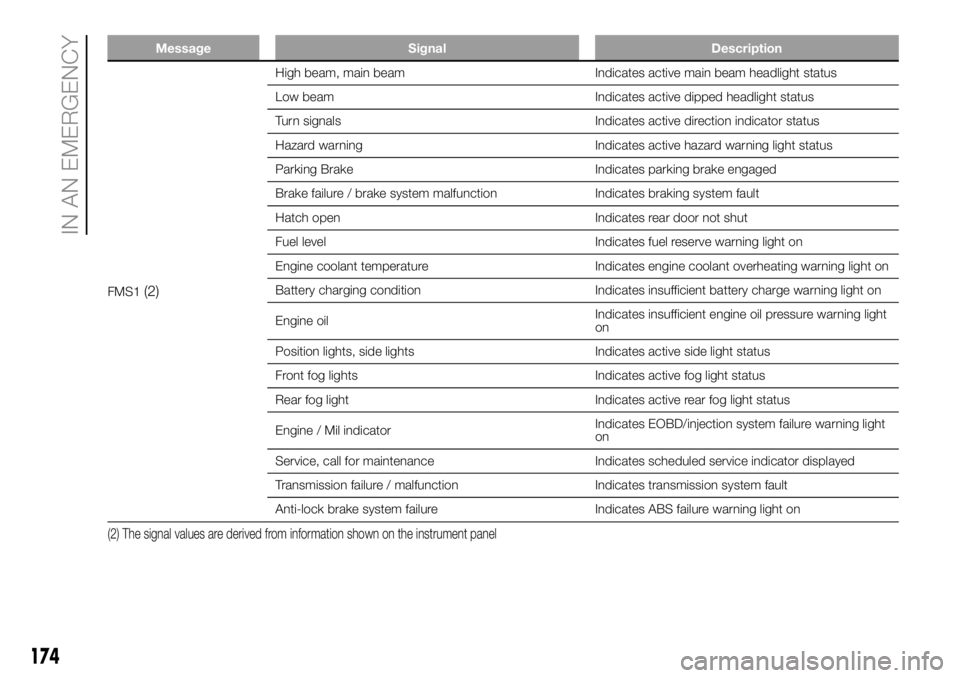
High beam, main beam Indicates active main beam headlight status
Low beam Indicates active dipped headlight status
Turn signals Indicates active direction indicator status
Hazard warning Indicates active hazard warning light status
Parking Brake Indicates parking brake engaged
Brake failure / brake system malfunction Indicates braking system fault
Hatch open Indicates rear door not shut
Fuel level Indicates fuel reserve warning light on
Engine coolant temperature Indicates engine coolant overheating warning light on
Battery charging condition Indicates insufficient battery charge warning light on
Engine oilIndicates insufficient engine oil pressure warning light
on
Position lights, side lights Indicates active side light status
Front fog lights Indicates active fog light status
Rear fog light Indicates active rear fog light status
Engine / Mil indicatorIndicates EOBD/injection system failure warning light
on
Service, call for maintenance Indicates scheduled service indicator displayed
Transmission failure / malfunction Indicates transmission system fault
Anti-lock brake system failure Indicates ABS failure warning light on
(2) The signal values are derived from information shown on the instrument panel
174
IN AN EMERGENCY
Page 177 of 304
Message Signal Description
FMS1(2)
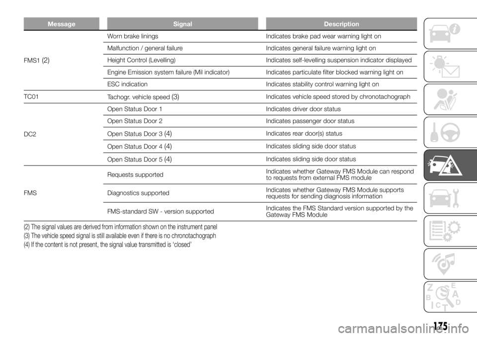
Worn brake linings Indicates brake pad wear warning light on
Malfunction / general failure Indicates general failure warning light on
Height Control (Levelling) Indicates self-levelling suspension indicator displayed
Engine Emission system failure (Mil indicator) Indicates particulate filter blocked warning light on
ESC indication Indicates stability control warning light on
TC01
Tachogr. vehicle speed
(3)Indicates vehicle speed stored by chronotachograph
DC2Open Status Door 1 Indicates driver door status
Open Status Door 2 Indicates passenger door status
Open Status Door 3
(4)Indicates rear door(s) status
Open Status Door 4
(4)Indicates sliding side door status
Open Status Door 5
(4)Indicates sliding side door status
FMSRequests supportedIndicates whether Gateway FMS Module can respond
to requests from external FMS module
Diagnostics supportedIndicates whether Gateway FMS Module supports
requests for sending diagnosis information
FMS-standard SW - version supportedIndicates the FMS Standard version supported by the
Gateway FMS Module
(2) The signal values are derived from information shown on the instrument panel
(3) The vehicle speed signal is still available even if there is no chronotachograph
(4) If the content is not present, the signal value transmitted is ‘closed’
175
Page 178 of 304
CHANGING A WHEEL
GENERAL
INSTRUCTIONS
Wheel replacement and correct use of
the jack and spare wheel (for
versions/markets, where provided) call
for some precautions, which are listed
below.
146) 147) 148) 149) 150)
Please note that:
the jack weight is 4.5 kg;
the jack requires no adjustment;
the jack cannot be repaired: in the
event of a fault it must be replaced
by another original one;
no tool other than its cranking
device may be fitted on the jack.
151)
To change a wheel, proceed as
follows:
stop the vehicle in a position that is
not dangerous for oncoming traffic
where you can change the wheel safely.
The ground must be flat and sufficiently
compact;
switch off the engine and pull the
handbrake;
engage first gear or reverse;
put on the reflective safety jacket
(compulsory by law in certain countries)
before getting out of the vehicle;
indicate that the vehicle has broken
down using the devices required by
the law in the current country (e.g.
warning triangle, hazard lights, etc.);
in the event of a wheel change on a
slope or on unsurfaced roads, put
any object as stop under the wheels;
take the tool bag from under the
passenger seat (see "Compartment
under the front passenger side seat" in
the "Internal equipment" chapter in
"Knowing the vehicle").
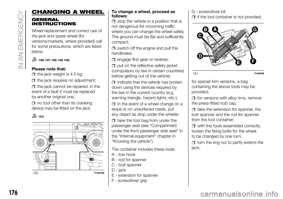
The container includes these tools:
A - tow hook
B - rod for spanner
C - bolt spanner
D - jack
E - extension for spanner
F - screwdriver gripG - screwdriver bit
if the tool container is not provided,
for special trim versions, a bag
containing the above tools may be
provided;
for versions with alloy rims, remove
the press-fitted hub cap;
take the extension for spanner, the
bolt spanner and the rod for spanner
from the tool container;
with the tools assembled correctly,
loosen the fixing bolts for the wheel
to be changed by one turn;
turn the ring nut to partly extend the
jack;
180F1A0168
181F1A0420
176
IN AN EMERGENCY
Page 183 of 304
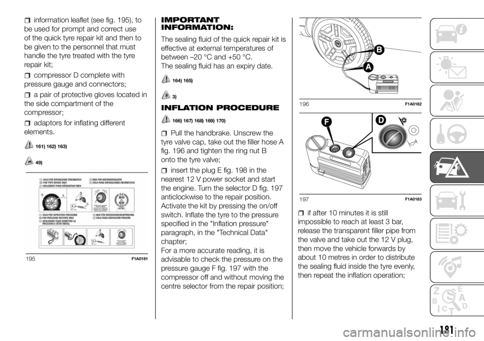
information leaflet (see fig. 195), to
be used for prompt and correct use
of the quick tyre repair kit and then to
be given to the personnel that must
handle the tyre treated with the tyre
repair kit;
compressor D complete with
pressure gauge and connectors;
a pair of protective gloves located in
the side compartment of the
compressor;
adaptors for inflating different
elements.
161) 162) 163)
49)
IMPORTANT
INFORMATION:
The sealing fluid of the quick repair kit is
effective at external temperatures of
between –20 °C and +50 °C.
The sealing fluid has an expiry date.
164) 165)
3)
INFLATION PROCEDURE
166) 167) 168) 169) 170)
Pull the handbrake. Unscrew the
tyre valve cap, take out the filler hose A
fig. 196 and tighten the ring nut B
onto the tyre valve;
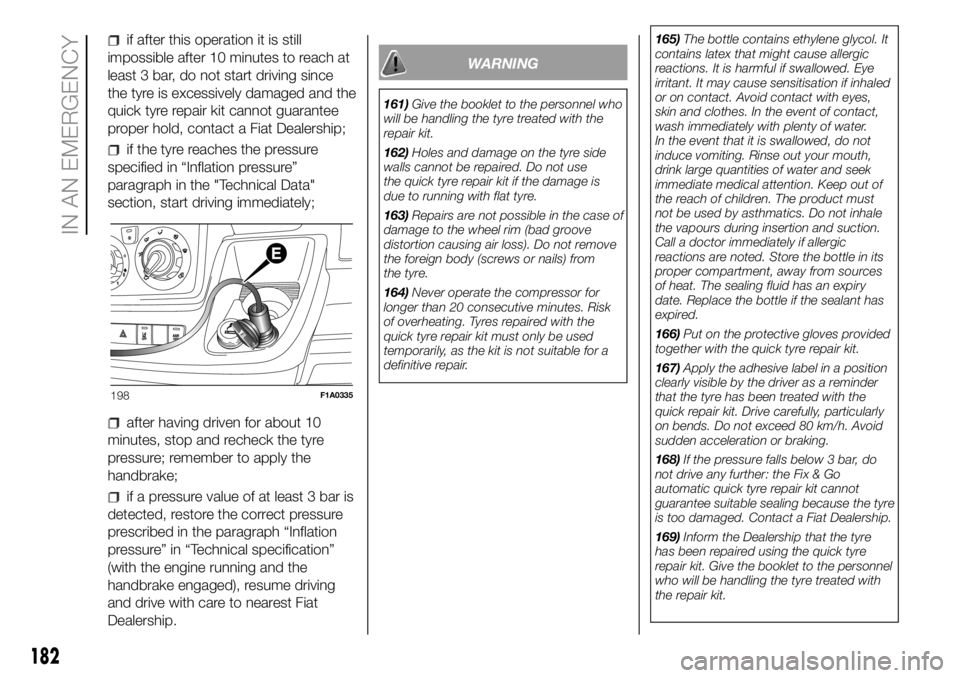
insert the plug E fig. 198 in the
nearest 12 V power socket and start
the engine. Turn the selector D fig. 197
anticlockwise to the repair position.
Activate the kit by pressing the on/off
switch. Inflate the tyre to the pressure
specified in the "Inflation pressure"
paragraph, in the "Technical Data"
chapter;
For a more accurate reading, it is
advisable to check the pressure on the
pressure gauge F fig. 197 with the
compressor off and without moving the
centre selector from the repair position;
if after 10 minutes it is still
impossible to reach at least 3 bar,
release the transparent filler pipe from
the valve and take out the 12 V plug,
then move the vehicle forwards by
about 10 metres in order to distribute
the sealing fluid inside the tyre evenly,
then repeat the inflation operation;
195F1A0181
196F1A0182
197F1A0183
181
Page 184 of 304
if after this operation it is still
impossible after 10 minutes to reach at
least 3 bar, do not start driving since
the tyre is excessively damaged and the
quick tyre repair kit cannot guarantee
proper hold, contact a Fiat Dealership;
if the tyre reaches the pressure
specified in “Inflation pressure”
paragraph in the "Technical Data"
section, start driving immediately;
after having driven for about 10
minutes, stop and recheck the tyre
pressure; remember to apply the
handbrake;
if a pressure value of at least 3 bar is
detected, restore the correct pressure
prescribed in the paragraph “Inflation
pressure” in “Technical specification”
(with the engine running and the
handbrake engaged), resume driving
and drive with care to nearest Fiat
Dealership.
WARNING
161)Give the booklet to the personnel who
will be handling the tyre treated with the
repair kit.
162)Holes and damage on the tyre side
walls cannot be repaired. Do not use
the quick tyre repair kit if the damage is
due to running with flat tyre.
163)Repairs are not possible in the case of
damage to the wheel rim (bad groove
distortion causing air loss). Do not remove
the foreign body (screws or nails) from
the tyre.
164)Never operate the compressor for
longer than 20 consecutive minutes. Risk
of overheating. Tyres repaired with the
quick tyre repair kit must only be used
temporarily, as the kit is not suitable for a
definitive repair.165)The bottle contains ethylene glycol. It
contains latex that might cause allergic
reactions. It is harmful if swallowed. Eye
irritant. It may cause sensitisation if inhaled
or on contact. Avoid contact with eyes,
skin and clothes. In the event of contact,
wash immediately with plenty of water.
In the event that it is swallowed, do not
induce vomiting. Rinse out your mouth,
drink large quantities of water and seek
immediate medical attention. Keep out of
the reach of children. The product must
not be used by asthmatics. Do not inhale
the vapours during insertion and suction.
Call a doctor immediately if allergic
reactions are noted. Store the bottle in its
proper compartment, away from sources
of heat. The sealing fluid has an expiry
date. Replace the bottle if the sealant has
expired.
166)Put on the protective gloves provided
together with the quick tyre repair kit.
167)Apply the adhesive label in a position
clearly visible by the driver as a reminder
that the tyre has been treated with the
quick repair kit. Drive carefully, particularly
on bends. Do not exceed 80 km/h. Avoid
sudden acceleration or braking.
168)If the pressure falls below 3 bar, do
not drive any further: the Fix & Go
automatic quick tyre repair kit cannot
guarantee suitable sealing because the tyre
is too damaged. Contact a Fiat Dealership.
169)Inform the Dealership that the tyre
has been repaired using the quick tyre
repair kit. Give the booklet to the personnel
who will be handling the tyre treated with
the repair kit.
198F1A0335
182
IN AN EMERGENCY
Page 185 of 304
170)If different tyres from the ones
supplied with the vehicle are used, it may
not be possible to carry out the repair. If
the tyres are replaced, it is advisable to use
those approved by the manufacturer.
Consult a Fiat Dealership.
WARNING
49)In the event of a puncture caused by
foreign bodies, the kit may be used to
repair tyres showing damage on the tread
or shoulder up to max 4 mm diameter.
WARNING
3)Replace the bottle if the sealant has
expired. Dispose of the bottle and the
sealant properly. Have them disposed of in
compliance with national and local
regulations.
JUMP STARTING
If the warning lightremains on
continuously on the instrument panel,
contact the Fiat Dealership immediately.
JUMP STARTING
If the battery is flat, it is possible to start
the engine using an auxiliary battery
with the same capacity or a little higher
than the flat one.
It is advisable to contact a Fiat
Dealership to check/replace the battery.
171)
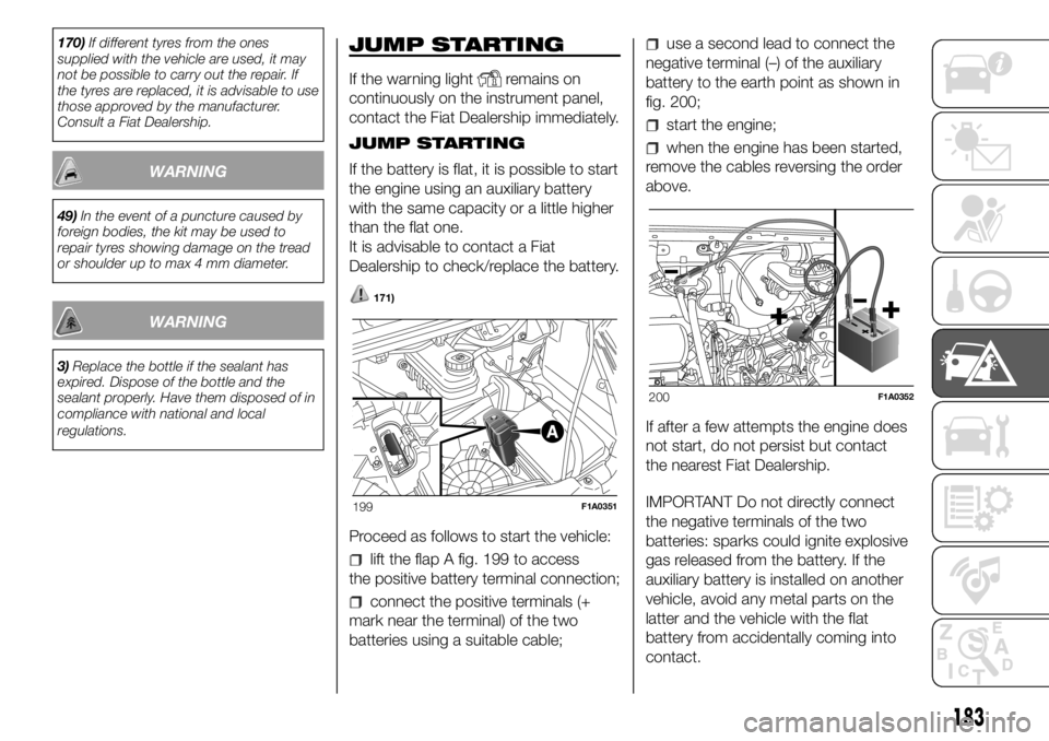
Proceed as follows to start the vehicle:
lift the flap A fig. 199 to access
the positive battery terminal connection;
connect the positive terminals (+
mark near the terminal) of the two
batteries using a suitable cable;
use a second lead to connect the
negative terminal (–) of the auxiliary
battery to the earth point as shown in
fig. 200;
start the engine;
when the engine has been started,
remove the cables reversing the order
above.
If after a few attempts the engine does
not start, do not persist but contact
the nearest Fiat Dealership.
IMPORTANT Do not directly connect
the negative terminals of the two
batteries: sparks could ignite explosive
gas released from the battery. If the
auxiliary battery is installed on another
vehicle, avoid any metal parts on the
latter and the vehicle with the flat
battery from accidentally coming into
contact.
199F1A0351
200F1A0352
183
Page 186 of 304
BUMP STARTING
Never bump start the engine by
pushing, towing or driving downhill.
This could cause fuel to flow into the
catalytic converter and damage it
beyond repair.
WARNING
171)This starting procedure must be
performed by expert personnel because
incorrect actions could cause electrical
discharge of considerable intensity.
Furthermore, battery fluid is poisonous and
corrosive: avoid contact with skin and
eyes. Keep naked flames and lighted
cigarettes away from the battery and do
not cause sparks.
BATTERY
RECHARGING
IMPORTANT The battery recharging
procedure is given as information only.
To carry out this operation contact a
Fiat Dealership.
IMPORTANT After setting the ignition
device to STOP and having closed the
driver side door, wait at least one
minute before disconnecting the
electrical supply from the battery. When
reconnecting the electrical supply to
the battery, make sure that the ignition
device is in the STOP position and
the driver side door is closed.
IMPORTANT Charging should be slow
at a low ampere rating for
approximately 24 hours. Charging for a
longer time may damage the battery.IMPORTANT The cables of the
electrical system must be correctly
reconnected to the battery, i.e. the
positive cable (+) to the positive
terminal and the negative cable (–) to
the negative terminal. The battery
terminals are marked with the positive
(+) and negative (–) symbols, and are
shown on the battery cover. The battery
terminals must also be corrosion-free
and firmly secured to the terminals. If a
"quick-type" battery charger is used
with the battery fitted on the car,
disconnect both battery leads before
connecting it. Do not use a "quick-type"
battery charger to provide the starting
voltage.
172) 173)
VERSIONS WITHOUT
START&STOP SYSTEM
To recharge, proceed as follows:
disconnect the terminal from the
negative battery pole;
connect the charger cables to the
battery terminals, observing the polarity;
turn on the battery charger;
when it is recharged, turn the
charger off before disconnecting it from
the battery;
reconnect the terminal to the
negative battery pole.
184
IN AN EMERGENCY
Page 187 of 304
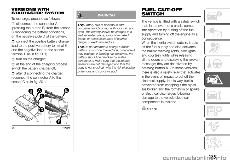
VERSIONS WITH
START&STOP SYSTEM
To recharge, proceed as follows:
disconnect the connector A
(pressing the button B) from the sensor
C monitoring the battery conditions,
on the negative pole D of the battery;
connect the positive battery charger
lead to the positive battery terminal E
and the negative lead to the sensor
terminal F as in fig. 201;
turn on the charger;
at the end of the charging process,
switch the battery charger off;
after disconnecting the charger,
reconnect the connector A to the
sensor C as in fig. 201.
WARNING
172)Battery fluid is poisonous and
corrosive: avoid contact with your skin and
eyes. The battery should be charged in a
well ventilated place, away from naked
flames or possible sources of sparks:
danger of explosion and fire.
173)Do not attempt to charge a frozen
battery: it must be thawed first, otherwise it
may explode. If freezing has occurred, the
battery should be checked by skilled
personnel to make sure that the internal
elements are not damaged and that the
body is not cracked, with the risk of leaking
poisonous and corrosive acid.
FUEL CUT-OFF
SWITCH
The vehicle is fitted with a safety switch
that, in the event of a crash, comes
into operation by cutting off the fuel
supply and turning off the engine as a
consequence.
When the inertia switch cuts in, it cuts
off the fuel supply and also activates
the hazard warning lights, side lights
and courtesy lights while releasing
all the doors and displaying the relevant
message; they are deactivated by
pressing button A. On some versions,
there is also a safety relay that activates
in the event of impact to cut off the
electrical supply. In this way, fuel is
prevented from escaping if the pipes
are broken and the formation of sparks
or electrical discharges following
damage to the vehicle electrical
components is avoided.
174) 175)
201F1A0219
185