buttons FIAT DUCATO BASE CAMPER 2018 Owner handbook (in English)
[x] Cancel search | Manufacturer: FIAT, Model Year: 2018, Model line: DUCATO BASE CAMPER, Model: FIAT DUCATO BASE CAMPER 2018Pages: 304, PDF Size: 14.93 MB
Page 41 of 304

Air distribution ring nut C
to convey air to the central and
side vents;
to warm the feet and convey
slightly cooler air to the dashboard
vents, in intermediate temperature
conditions;
for heating when the outside
temperature is very low: to direct
as much air as possible to the
feet;
to warm the feet and demist the
windscreen at the same time;
for quick windscreen demisting.
Air recirculation on/off knob D
Press the button (button LED on) to
turn the internal air recirculation on.
Press the button again (button LED off)
to turn the internal air recirculation off.
Climate control system on/off
button E
Press the button (button LED on) to
turn the climate control system on.
Press the button again (button LED off)
to turn the climate control system off.
AUTOMATIC
CLIMATE CONTROL
SYSTEM
2)
(for versions/markets, where provided)
CONTROLS
AAUTO button automatic control of all
functions.
BAir distribution selection button.
CDisplay.
DMAX DEF function control button.
ESystem off button.
FCompressor enabling/disabling
control button.
GAir recirculation control button.
HFan speed increase/decrease control
buttons.
ITemperature increase/decrease
control knob.USING THE CLIMATE
CONTROL SYSTEM
The system can be started in different
ways, but it is advisable to start by
pressing the AUTO button and then
turning the knob to set the temperature
required on the display.
The system will adjust the temperature,
the quantity and the distribution of the
air sent into the passenger
compartment and, by managing the
recirculation function, the activation of
the climate control system compressor.
During fully automatic operation, the
only manual intervention required is the
possible activation of the following
functions:
air recirculation (to keep the
recirculation constantly on or constantly
off);
to speed up demisting/
defrosting the windscreen, rearscreen
and external rear-view mirrors.
74F1A0054
39
Page 42 of 304
During fully automatic system
operation, you can change the set
temperature, air distribution and fan
speed at any time by using the relevant
buttons or knobs: the system will
automatically change its settings to
adjust to the new requirements. During
fully automatic operation (FULL AUTO),
the word FULL will disappear if the air
distribution and/or flow rate and/or
engagement of the compressor and/or
recirculation settings are changed. In
this way, the functions will switch from
automatic to manual control until the
AUTO button is pressed again.
WARNING
2)The air conditioning system uses R134a
or R1234yf refrigerant compatible with
the regulations in force in the countries
where the vehicle is sold. When charging,
only use the gas indicated on the
dedicated plate in the engine compartment
. The use of other coolants affects the
efficiency and condition of the system. The
lubricant used for the compressor is also
strictly linked to the type of cooling gas,
please refer to a Fiat Dealership.
ADDITIONAL
HEATER
(for versions/markets, where provided)
On some versions, an additional heater
is also present beneath the driver's
seat. The fan for this heater is operated
by means of the button F located on
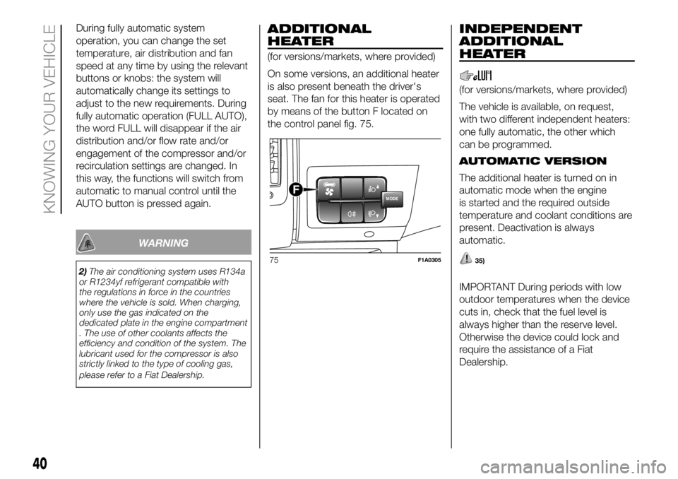
the control panel fig. 75.
INDEPENDENT
ADDITIONAL
HEATER
(for versions/markets, where provided)
The vehicle is available, on request,
with two different independent heaters:
one fully automatic, the other which
can be programmed.
AUTOMATIC VERSION
The additional heater is turned on in
automatic mode when the engine
is started and the required outside
temperature and coolant conditions are
present. Deactivation is always
automatic.
35)
IMPORTANT During periods with low
outdoor temperatures when the device
cuts in, check that the fuel level is
always higher than the reserve level.
Otherwise the device could lock and
require the assistance of a Fiat
Dealership.
MODEF
75F1A0305
40
KNOWING YOUR VEHICLE
Page 43 of 304
PROGRAMMABLE
VERSION
The additional heater operates
completely independently of engine
operation and allows the following:
heating the passenger compartment
with the engine off
defrosting the windows;
heat the engine coolant and then the
engine itself prior to starting.
The system consists of:
a diesel burner for heating the water
with an exhaust silencer for the
combustion gases;
a metering pump connected to the
reservoir pipes for supplying the burner;
a heat exchanger connected to the
engine cooling system pipes;
a control unit connected to the
passenger compartment heating/
ventilation system to allow automatic
operation;
an electronic control unit for
controlling and adjusting the built-in
burner;
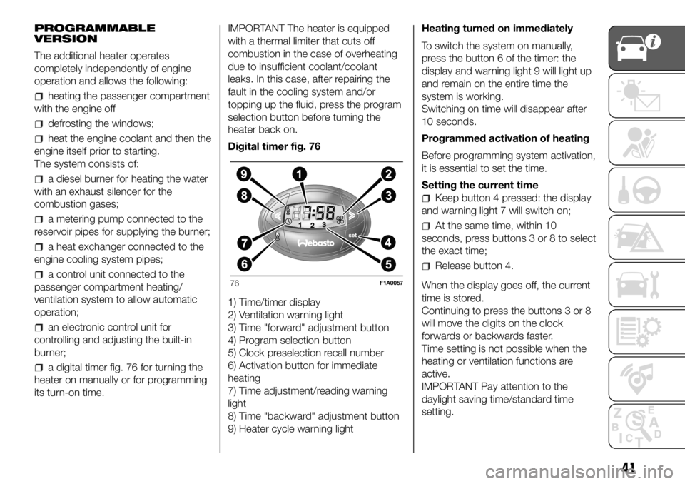
a digital timer fig. 76 for turning the
heater on manually or for programming
its turn-on time.IMPORTANT The heater is equipped
with a thermal limiter that cuts off
combustion in the case of overheating
due to insufficient coolant/coolant
leaks. In this case, after repairing the
fault in the cooling system and/or
topping up the fluid, press the program
selection button before turning the
heater back on.
Digital timer fig. 76
1) Time/timer display
2) Ventilation warning light
3) Time "forward" adjustment button
4) Program selection button
5) Clock preselection recall number
6) Activation button for immediate
heating
7) Time adjustment/reading warning
light
8) Time "backward" adjustment button
9) Heater cycle warning lightHeating turned on immediately
To switch the system on manually,
press the button 6 of the timer: the
display and warning light 9 will light up
and remain on the entire time the
system is working.
Switching on time will disappear after
10 seconds.
Programmed activation of heating
Before programming system activation,
it is essential to set the time.
Setting the current time
Keep button 4 pressed: the display
and warning light 7 will switch on;
At the same time, within 10
seconds, press buttons 3 or 8 to select
the exact time;
Release button 4.
When the display goes off, the current
time is stored.
Continuing to press the buttons 3 or 8
will move the digits on the clock
forwards or backwards faster.
Time setting is not possible when the
heating or ventilation functions are
active.
IMPORTANT Pay attention to the
daylight saving time/standard time
setting.
76F1A0057
41
Page 44 of 304

Programming the switching on time
To program the activation time:
press button 4: the symbol 10 or the
time set previously and the number 5
corresponding to the preselection
recalled will light up in the display for 10
seconds.
IMPORTANT If you wish to recall other
preselected times, press button 4
from time to time within 10 seconds.
– within 10 seconds, press the buttons
3 or 8 to select the desired switching
on time.
IMPORTANT The confirmation that the
time has been memorised is given by:
the disappearance of the switching
on time;
the presence of the preselection
number 5;
the lighting of the display.
IMPORTANT When the boiler comes
on:
the flame warning light 9 switches
on in the display;
the preselection number 5 goes out.
Standard settings:
Preselected time 1: 6:00
Preselected time 2: 16:00
Preselected time 3: 22:00IMPORTANT Factory pre-settings are
cancelled with a new setting.
Preselected times are stored until the
following change. If the clock is
detached from the on-board network
(e.g. if the battery is disconnected), the
factory pre-settings are restored.
Deactivation of the programmed
switching on time
To delete the programmed activation
time, press button 4 briefly: the display
lighting will go off and the number 5
relating to the preselected time will
disappear.
Recalling one of the preselected
switching on times
Operate button 4 within 10 seconds
until the program number with the
desired preselected time is displayed.
The preselected time you have chosen
to set is automatically activated after
about 10 seconds without the need for
any further confirmation with another
button.
Activate the preselected time taking
into account the safety instructions for
the operation of the independent
heating (for this purpose consult the
Owner's Manual for use of independent
heating).IMPORTANT Independent heating
switches on at the preselected time,
both with vehicle parked and while
driving.
IMPORTANT The programmed
switching on time can be altered or
cancelled by following the instructions
given previously.
Operation duration setting
Hold the button pressed. At the same
time press button 3 or 8.
The time and warning light 7 are
displayed.
Press the button 4 again and hold it
down. At the same time press the
button 3 or 8.
The preset activation duration is
displayed and warning light 9 or 2
flashes.
Set the activation duration with button
3or8.
The set activation duration is stored as
soon as the text in the display
disappears, or pressing button 4.
Switching the heating system off
Deactivation of the system, depending
on the type of activation (automatic
or manual), may be:
automaticwhen the programmed
duration is over; when the set time is
over, the display switches off.
42
KNOWING YOUR VEHICLE
Page 46 of 304
Turn the knob D to the maximum
heating position (knob at red
sector);warm air will emerge (with the
engine warmed up), from the rear
footwell outlets (located under the seats
in the 2nd and 3rd row for Panorama
versions and the grille on the left wheel
arch side for Combi versions).
ADDITIONAL REAR
CLIMATE CONTROL
(Panorama and Combi)
(for versions/markets, where provided)
The Panorama and Combi versions
are equipped with a main heating/air
conditioning system plus an additional
system (available on request) with
controls in the roof panel trim above the
second row of seats fig. 77. Button F
fig. 78 on the control panel must be
enabled for operation; the air
conditioning only works if the main
climate control system is on.
When the knob D is placed in the
fully cold position (control in blue sector)
cold air comes out the vents in the
ceiling.
Turn the knob D to the maximum
heating position (knob at red
sector);warm air will emerge (with the
engine warmed up), from the rear
footwell outlets (located under the seats
in the 2nd and 3rd row for Panorama
versions and the grille on the left wheel
arch side for Combi versions).
If the selector knob D is placed in
the intermediate positions, the air
will be distributed between the vents in
the ceiling and the rear footwell vents,
varying the temperature.
IMPORTANT If the compressor on the
main climate control system control
is turned on (operation of button E),
even if the additional climate control
system fan is in position 0, the 1st
speed will automatically be activated to
prevent ice formation, with possible
damage to the component.
WARNING
35)The heater burns fuel in the same way
as the engine, though to a lesser extent. To
prevent poisoning and asphyxiation, the
supplementary heater must never be
turned on, not even for short periods, in
closed environments such as a garage or
workshops without extraction fans for
the exhaust gases.
ELECTRIC WINDOWS
ELECTRIC
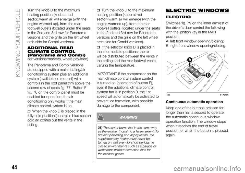
Switches fig. 79 on the inner armrest of
the driver's door control the following
with the ignition key in the MAR
position:
A: left front window opening/closing;
B: right front window opening/closing.
Continuous automatic operation
Keep one of the buttons pressed for
longer than half a second to operate
the automatic continuous window
operation function. The window stops
when it reaches the end of travel
position, or when the button is pressed
again.
79F1A0125
44
KNOWING YOUR VEHICLE
Page 48 of 304
IMPORTANT Always check that the
bonnet is closed correctly to prevent it
from opening while the vehicle is
travelling.
37) 38) 39)
WARNING
37)For safety reasons, the bonnet must
always be perfectly closed while travelling.
Make sure that the bonnet is perfectly
closed and that the lock is engaged. If you
notice when driving that the bonnet has
not been properly locked, stop immediately
and close the bonnet correctly.
38)Incorrect positioning of the stay rod
may cause the bonnet to drop suddenly.
39)Perform these operations only when
the vehicle is stationary.
HEAD RESTRAINTS
FRONT
On certain versions the head restraints
are adjustable in height and they lock
automatically in the required position.
40)
Adjustment
Upward adjustment: lift the head
restraint until it clicks into place.
Downwards adjustment: press the
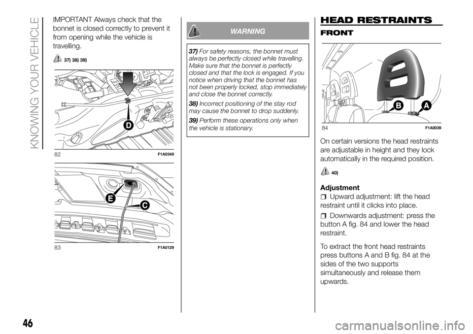
button A fig. 84 and lower the head
restraint.
To extract the front head restraints
press buttons A and B fig. 84 at the
sides of the two supports
simultaneously and release them
upwards.
82F1A0349
83F1A0129
84F1A0039
46
KNOWING YOUR VEHICLE
Page 52 of 304
the system has reached a threshold
working temperature: wait a few
minutes to let it cool down before
operating the buttons again.
The level selected with the vehicle
stationary is maintained up to a speed
of about 20 km/h; when this speed
is exceeded, the system will
automatically restore the normal level:
"ride setting 0".
WARNING
5)Before manually adjusting with doors
open, make sure there is enough space
around the vehicle for this kind of
operation.
ACCESSORIES
PURCHASED BY THE
OWNER
PROVISION FOR FITTING
TELEPASS ON
REFLECTIVE
WINDSCREEN
(for versions/markets, where provided)
If the vehicle is equipped with a
reflective windscreen, install the
Telepass in the appropriate area shown
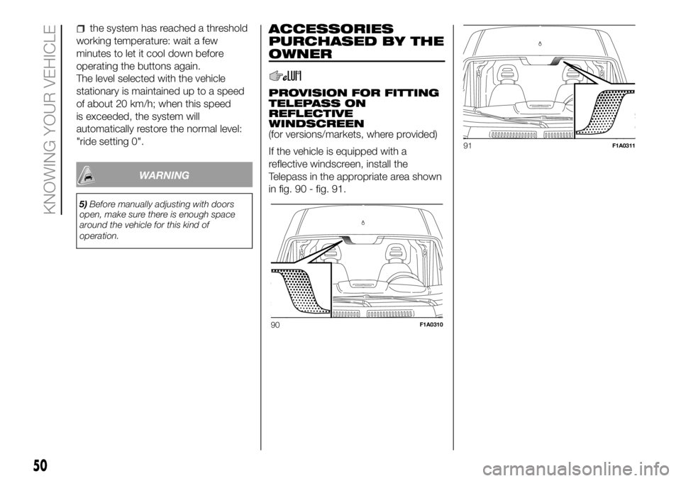
in fig. 90 - fig. 91.
90F1A0310
91F1A0311
50
KNOWING YOUR VEHICLE
Page 59 of 304
ENGINE OIL LEVEL
GAUGE
(for versions/markets, where provided)
The gauge provides a graphic indication
of the level of oil in the engine.
When the ignition key is turned to the
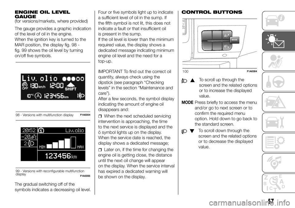
MAR position, the display fig. 98 -
fig. 99 shows the oil level by turning
on/off five symbols.
The gradual switching off of the
symbols indicates a decreasing oil level.Four or five symbols light up to indicate
a sufficient level of oil in the sump. If
the fifth symbol is not lit, this does not
indicate a fault or that insufficient oil
is present in the sump.
If the oil level is lower than the minimum
required value, the display shows a
dedicated message indicating minimum
engine oil level and the need for a
top-up.
IMPORTANT To find out the correct oil
quantity, always check using the
dipstick (see paragraph “Checking
levels” in the section “Maintenance and
care”).
After a few seconds, the symbol display
indicating the amount of engine oil
disappears and:
When the next scheduled servicing
intervention is approaching, the time
to the next service is displayed and the
õ symbol lights up on the display.
When the service date is reached, the
display shows a dedicated message;
Later on, if the time for changing the
engine oil is getting close, the distance
until the next oil change will appear
on the display. When the service interval
has expired a dedicated warning will
be shown on the display.CONTROL BUTTONS
To scroll up through the
screen and the related options
or to increase the displayed
value.
MODEPress briefly to access the menu
and/or go to next screen or to
confirm the required menu
option. Hold down to go back to
the standard screen.
To scroll down through the
screen and the related options
or to decrease the displayed
value.
98 - Versions with multifunction displayF1A0354
Liv.olio
MAX MIN
99 - Versions with reconfigurable multifunction
displayF1A0355
MODE
100F1A0304
57
Page 60 of 304
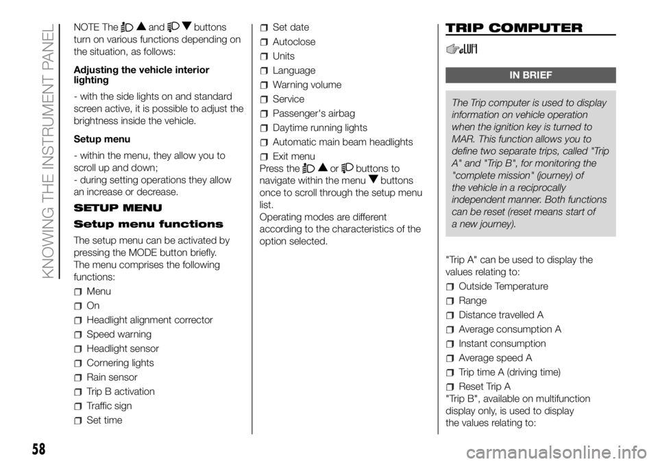
NOTE Theandbuttons
turn on various functions depending on
the situation, as follows:
Adjusting the vehicle interior
lighting
- with the side lights on and standard
screen active, it is possible to adjust the
brightness inside the vehicle.
Setup menu
- within the menu, they allow you to
scroll up and down;
- during setting operations they allow
an increase or decrease.
SETUP MENU
Setup menu functions
The setup menu can be activated by
pressing the MODE button briefly.
The menu comprises the following
functions:
Menu
On
Headlight alignment corrector
Speed warning
Headlight sensor
Cornering lights
Rain sensor
Trip B activation
Traffic sign
Set time
Set date
Autoclose
Units
Language
Warning volume
Service
Passenger's airbag
Daytime running lights
Automatic main beam headlights
Exit menu
Press the
orbuttons to
navigate within the menu
buttons
once to scroll through the setup menu
list.
Operating modes are different
according to the characteristics of the
option selected.
TRIP COMPUTER
IN BRIEF
The Trip computer is used to display
information on vehicleoperation
when the ignition key is turned to
MAR. This function allows you to
define two separate trips, called "Trip
A" and "Trip B", for monitoring the
"complete mission" (journey) of
the vehicle in a reciprocally
independent manner. Both functions
can be reset (reset means start of
a new journey).
"Trip A" can be used to display the
values relating to:
Outside Temperature
Range
Distance travelled A
Average consumption A
Instant consumption
Average speed A
Trip time A (driving time)
Reset Trip A
"Trip B", available on multifunction
display only, is used to display
the values relating to:
58
KNOWING THE INSTRUMENT PANEL
Page 179 of 304
position the jack at the lifting support
nearest the wheel to be replaced, at
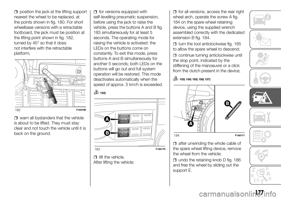
the points shown in fig. 180. For short
wheelbase versions with a retractable
footboard, the jack must be position at
the lifting point shown in fig. 182,
turned by 45° so that it does
not interfere with the retractable
platform;
warn all bystanders that the vehicle
is about to be lifted. They must stay
clear and not touch the vehicle until it is
back on the ground.
for versions equipped with
self-levelling pneumatic suspension,
before using the jack to raise the
vehicle, press the buttons A and B fig.
183 simultaneously for at least 5
seconds. The operating mode for
raising the vehicle is activated: the
LEDs on the buttons come on
constantly. To exit this mode, press
buttons A and B simultaneously for
another 5 seconds; both LEDs on the
buttons will go out and full system
operation will be restored. This mode
deactivates automatically when the
speed of approx. 5 km/h is exceeded.
152)
lift the vehicle.
After lifting the vehicle:
for all versions, access the rear right
wheel arch, operate the screw A fig.
184 on the spare wheel retaining
device, using the supplied wrench
assembled correctly with the dedicated
extension B fig. 184.
turn the tool anticlockwise fig. 185
to allow the spare wheel to descend;
continue turning anticlockwise until
the stop point, indicated by the
stiffening of the manoeuvre or a click
from the clutch present in the device;
153) 154) 155) 156) 157)
after unwinding the whole cable of
the spare wheel lifting device, remove
the wheel from the vehicle;
undo the retaining knob D fig. 186
and free the wheel by sliding out the
support E.
182F1A0169
183F1A0170
184F1A0171
177