display FIAT FIORINO 2007 Owner handbook (in English)
[x] Cancel search | Manufacturer: FIAT, Model Year: 2007, Model line: FIORINO, Model: FIAT FIORINO 2007Pages: 210, PDF Size: 3.22 MB
Page 31 of 210
30
SAFETY
STARTING
AND DRIVING
WARNING
LIGHTS AND
MESSAGES
IN AN
EMERGENCY
MAINTENANCE
AND CARE
TECHNICAL
SPECIFICATIONS
INDEX
DASHBOARD
AND CONTROLS
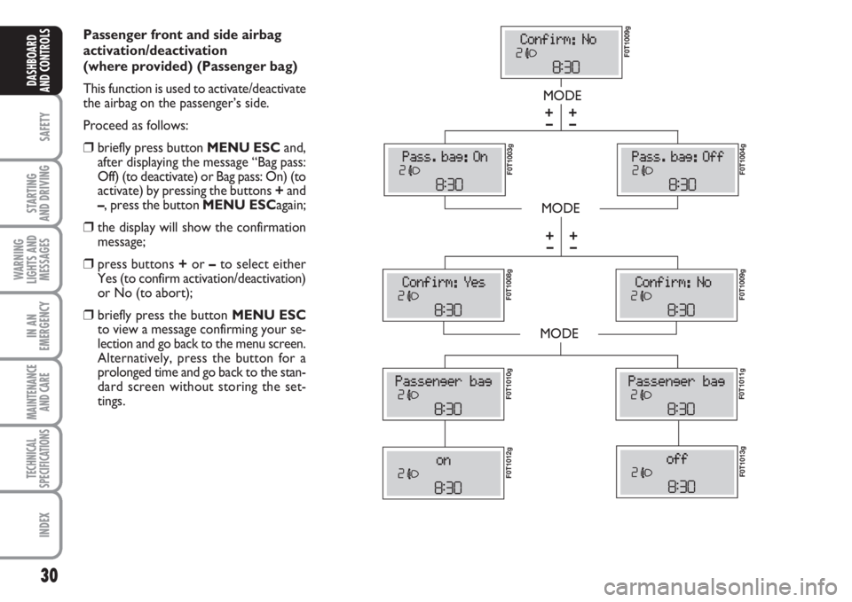
Passenger front and side airbag
activation/deactivation
(where provided) (Passenger bag)
This function is used to activate/deactivate
the airbag on the passenger’s side.
Proceed as follows:
❒briefly press button MENU ESCand,
after displaying the message “Bag pass:
Off) (to deactivate) or Bag pass: On) (to
activate) by pressing the buttons +and
–, press the button MENU ESCagain;
❒the display will show the confirmation
message;
❒press buttons +or –to select either
Yes (to confirm activation/deactivation)
or No (to abort);
❒briefly press the button MENU ESC
to view a message confirming your se-
lection and go back to the menu screen.
Alternatively, press the button for a
prolonged time and go back to the stan-
dard screen without storing the set-
tings.
MODE
MODE
MODE
– +
– +
F0T1009g F0T1003g
F0T1004g F0T1008g
F0T1009g F0T1011gF0T1010g
F0T1012gF0T1013g
– +
– +
Page 32 of 210
31
SAFETY
STARTING
AND DRIVING
WARNING
LIGHTS AND
MESSAGES
IN AN
EMERGENCY
MAINTENANCE
AND CARE
TECHNICAL
SPECIFICATIONS
INDEX
DASHBOARD
AND CONTROLS
TRIP COMPUTER
General features
The “Trip computer” is used to display in-
formation on vehicle operation when the
key is turned to MAR. This function al-
lows to define two separate trips called
“Trip A” and “Trip B” for monitoring the
“complete mission” of the vehicle (trip) in
a reciprocally independent manner. Both
functions are resettable (reset - start of
new mission).
“Trip A” is used to display data relating to:
– Range
– Trip distance
– Average consumption
– Instant consumption
– Average speed
– Travel time (driving time).
“Trip B” is supplied on versions having a
multifunctional display and is used to dis-
play data relating to:
– Trip distance B
– Average consumption B
– Average speed B
– Travel time B (driving time).
Note“Trip B” functions may be disabled
(see paragraph “Trip B on”). “Range” and
“Instant consumption” cannot be reset.Values displayed
Range
Indicates the travel distance left before the
vehicle runs out of the fuel in the tank.
The message “----” will appear on the dis-
play in the following cases:
– value lower than 50 km (or 30 mi)
– vehicle left parked with engine running
for long.
IMPORTANT Changes of the range value
can be affected by many factors: driving
style (see paragraph “Driving style” in sec-
tion “Starting and driving”), type of route
(motorway, urban cycle, mountain roads,
etc…), conditions of use of the vehicle
(load, tyre pressure, etc…). Trip planning
must take into account the above notes. Exit Menu
This is the last function that closes the set-
ting cycle listed in the initial menu screen.
Briefly press button MENU ESCto go
back to the standard screen without stor-
ing settings.
Press button –to return to the first menu
option (Speed Beep).
Page 33 of 210
32
SAFETY
STARTING
AND DRIVING
WARNING
LIGHTS AND
MESSAGES
IN AN
EMERGENCY
MAINTENANCE
AND CARE
TECHNICAL
SPECIFICATIONS
INDEX
DASHBOARD
AND CONTROLS
Trip distance
Indicates the distance covered from the
start of a new mission.
Average consumption
Represents the approximate average con-
sumption from the start of a new mission.
Instant consumption
Indicates the fuel consumption. The val-
ue is constantly updated. The message
“----” will appear on the display if the ve-
hicle is parked with the engine running.
Average speed
Represents the vehicle average speed as a
function of the overall time elapsed since
the start of a new mission.
Trip time
Indicates the time elapsed since the start
of a new mission.
IMPORTANT If information is not avail-
able, the message “----” will appear instead
of the Trip Computer values. Counting of
the different values will be resumed reg-
ularly when normal operation is restored.
This will not cause any resetting of the val-
ues displayed before the failure nor start-
ing a new mission.
fig. 20F0T0038m
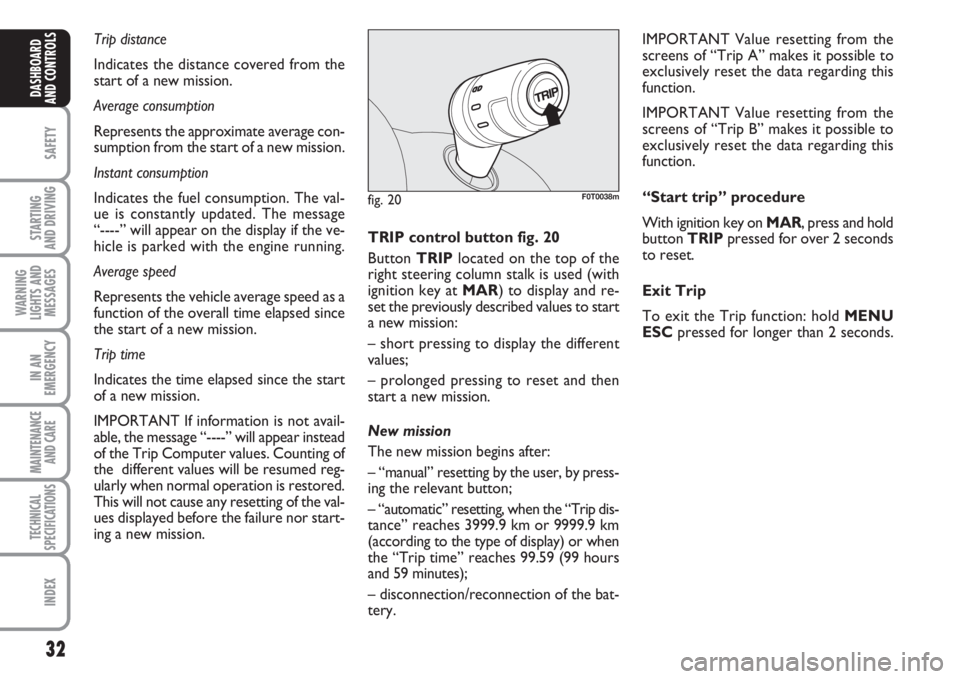
TRIP control button fig. 20
Button TRIPlocated on the top of the
right steering column stalk is used (with
ignition key at MAR) to display and re-
set the previously described values to start
a new mission:
– short pressing to display the different
values;
– prolonged pressing to reset and then
start a new mission.
New mission
The new mission begins after:
– “manual” resetting by the user, by press-
ing the relevant button;
– “automatic” resetting, when the “Trip dis-
tance” reaches 3999.9 km or 9999.9 km
(according to the type of display) or when
the “Trip time” reaches 99.59 (99 hours
and 59 minutes);
– disconnection/reconnection of the bat-
tery.IMPORTANT Value resetting from the
screens of “Trip A” makes it possible to
exclusively reset the data regarding this
function.
IMPORTANT Value resetting from the
screens of “Trip B” makes it possible to
exclusively reset the data regarding this
function.
“Start trip” procedure
With ignition key on MAR, press and hold
button TRIPpressed for over 2 seconds
to reset.
Exit Trip
To exit the Trip function: hold MENU
ESCpressed for longer than 2 seconds.
Page 51 of 210
50
SAFETY
STARTING
AND DRIVING
WARNING
LIGHTS AND
MESSAGES
IN AN
EMERGENCY
MAINTENANCE
AND CARE
TECHNICAL
SPECIFICATIONS
INDEX
DASHBOARD
AND CONTROLS
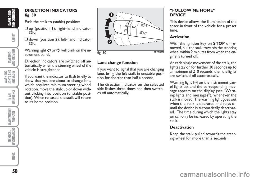
DIRECTION INDICATORS
fig. 50
Push the stalk to (stable) position:
❒up (position 1): right-hand indicator
ON;
❒down (position 2): left-hand indicator
ON.
Warning light
Îor ¥will blink on the in-
strument panel.
Direction indicators are switched off au-
tomatically when the steering wheel of the
vehicle is straightened.
If you want the indicator to flash briefly to
show that you are about to change lane,
which requires minimum steering wheel
rotation, move the stalk up or down with-
out clicking into position (unstable posi-
tion). When released, the stalk will return
to its home position.Lane change function
If you want to signal that you are changing
lane, bring the left stalk in unstable posi-
tion for shorter than half a second.
The direction indicator on the selected
side flashes three times and then switch-
es off automatically.“FOLLOW ME HOME”
DEVICE
This device allows the illumination of the
space in front of the vehicle for a preset
time.
Activation
With the ignition key on STOPor re-
moved, pull the stalk towards the steering
wheel within 2 minutes from when the en-
gine is turned off.
At each single movement of the stalk, the
lights stay on for further 30 seconds up to
a maximum of 210 seconds; then the lights
are switched off automatically.
Warning light
3on the instrument pan-
el lights up, and the corresponding mes-
sage appears on the display (see “Warn-
ing lights and messages”), whenever the
stalk is moved. The warning light goes out
when the stalk is operated and stays on
until the device is automatically deactivat-
ed. The time during which the lights stay
on can only be increased by operating the
stalk.
Deactivation
Keep the stalk pulled towards the steer-
ing wheel for more than 2 seconds.
fig. 50F0T0157m
Page 58 of 210

57
SAFETY
STARTING
AND DRIVING
WARNING
LIGHTS AND
MESSAGES
IN AN
EMERGENCY
MAINTENANCE
AND CARE
TECHNICAL
SPECIFICATIONS
INDEX
DASHBOARD
AND CONTROLS
FUEL CUT-OFF SYSTEM
This system triggers after a collision and
activates the following:
❒switch off of fuel supply with conse-
quent engine switch off;
❒automatic door unlocking;
❒switch on of all lights inside the vehicle.
When the system is triggered, the mes-
sage “Fuel cut-off tripped - see handbook”
is displayed on some versions.
Carefully check the vehicle for fuel leaks,
for instance in the engine compartment
below the vehicle or near the fuel tank
area.
After the collision, position ignition key on
STOPto avoid battery draining.To reset vehicle operation, follow this
procedure:
❒turn the ignition key to MAR;
❒activate the right-hand indicator;
❒deactivate the right-hand indicator;
❒activate the left-hand indicator;
❒deactivate the left-hand indicator;
❒activate the right-hand indicator;
❒deactivate the right-hand indicator;
❒activate the left-hand indicator;
❒deactivate the left-hand indicator;
❒turn the ignition key to STOP.
If, after a crash, you smell fu-
el or notice leaks from the
fuel system, do not reset the system
to avoid fire risk.
WARNING
Page 74 of 210
73
SAFETY
STARTING
AND DRIVING
WARNING
LIGHTS AND
MESSAGES
IN AN
EMERGENCY
MAINTENANCE
AND CARE
TECHNICAL
SPECIFICATIONS
INDEX
DASHBOARD
AND CONTROLS
HEADLIGHTS
DIRECTING THE BEAM
Correct direction of the headlights is es-
sential for the comfort and safety of the
driver and the other road users. To en-
sure the best visibility conditions during
travel with the headlights on the vehicle
must have beams aimed correctly. Con-
tact the Fiat Dealership to have the head-
lights checked and properly adjusted.
HEADLIGHT AIMING DEVICE
This device works with the key at MAR
and the dipped beam headlights on.
The vehicle slants backwards when it is
loaded, raising the beam. The beams must
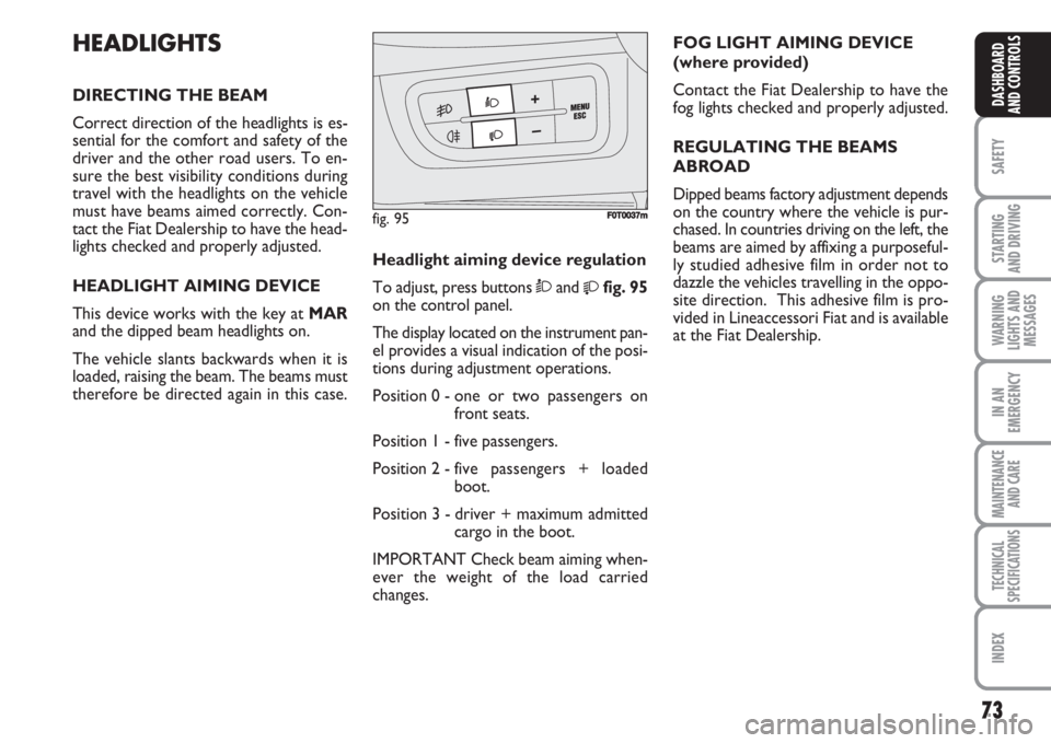
therefore be directed again in this case.Headlight aiming device regulation
To adjust, press buttons Òand
fig. 95
on the control panel.
The display located on the instrument pan-
el provides a visual indication of the posi-
tions during adjustment operations.
Position 0 - one or two passengers on
front seats.
Position 1 - five passengers.
Position 2 - five passengers + loaded
boot.
Position 3 - driver + maximum admitted
cargo in the boot.
IMPORTANT Check beam aiming when-
ever the weight of the load carried
changes.FOG LIGHT AIMING DEVICE
(where provided)
Contact the Fiat Dealership to have the
fog lights checked and properly adjusted.
REGULATING THE BEAMS
ABROAD
Dipped beams factory adjustment depends
on the country where the vehicle is pur-
chased. In countries driving on the left, the
beams are aimed by affixing a purposeful-
ly studied adhesive film in order not to
dazzle the vehicles travelling in the oppo-
site direction. This adhesive film is pro-
vided in Lineaccessori Fiat and is available
at the Fiat Dealership.
fig. 95F0T0037m
Page 76 of 210
75
SAFETY
STARTING
AND DRIVING
WARNING
LIGHTS AND
MESSAGES
IN AN
EMERGENCY
MAINTENANCE
AND CARE
TECHNICAL
SPECIFICATIONS
INDEX
DASHBOARD
AND CONTROLS
FAILURE INDICATIONS
ABS failure
ABS failure is indicated by the turning on
of warning light
>on the instrument pan-
el (together with the dedicated message
on the display in some versions) (see sec-
tion “Warning lights and messages”).
In the case, the braking system preserves
its efficiency, but cannot rely on the ex-
tra potentials offered by the ABS system.
Drive carefully to the nearest Fiat Deal-
ership to have the system checked.EBD failure
EBD failure is indicated by the turning on
of warning lights
>and xon the instru-
ment panel (together with the dedicated
message on the display in some versions)
(see section “Warning lights and mes-
sages”).
In this case, the rear wheels may sudden-
ly lock and the vehicle may swerve. Dri-
ve carefully to the nearest Fiat Dealership
to have the system checked.If warning light xonly lights
up on the instrument panel
(with a message on the display in
some versions), immediately stop the
vehicle and go to the nearest Fiat
Dealership. Leakage of hydraulic flu-
id from the braking system jeopardis-
es the functionality of the braking sys-
tem, either of the conventional type
or with ABS.
WARNING
Page 77 of 210
76
SAFETY
STARTING
AND DRIVING
WARNING
LIGHTS AND
MESSAGES
IN AN
EMERGENCY
MAINTENANCE
AND CARE
TECHNICAL
SPECIFICATIONS
INDEX
DASHBOARD
AND CONTROLS
EOBD SYSTEM
The EOBD system (European On Board
Diagnosis) allows continuous diagnosis of
emission-related components of the vehi-
cle. It also alerts the driver, by switching
on of the warning light Uon the instru-
ment panel (together with relevant mes-
sage on the display in some versions)
when these components are no longer in
peak conditions (see section “Warning
lights and messages”).
The objective of this system is:
❒to keep the system efficiency under
control;
❒to warn about increased emissions due
to a vehicle malfunction;
❒to warn of the need to replace deteri-
orated components.The system also has a diagnostic connector
that can be interfaced with appropriate
tools, which makes it possible to read the
error codes stored in the control unit to-
gether with a series of specific parameters
for engine operation and diagnosis.
This check can also be carried out by the
traffic police.
IMPORTANT After eliminating the prob-
lem, to check the system completely, Fi-
at Dealerships are obliged to run a bench
test and, if necessary, road tests which
may also call for a long journey.Go to a Fiat Dealership as
soon as possible if warning
light Udoes not light up when the
key is turned to MAR or if, during
travel, the warning light comes on ei-
ther steady or blinking (along with a
message on the display). The opera-
tion of the warning light Umay be
checked by the traffic police using
specific devices. Follow the laws in
force in the country where you are
driving.
WARNING
Page 83 of 210
82
SAFETY
STARTING
AND DRIVING
WARNING
LIGHTS AND
MESSAGES
IN AN
EMERGENCY
MAINTENANCE
AND CARE
TECHNICAL
SPECIFICATIONS
INDEX
DASHBOARD
AND CONTROLS
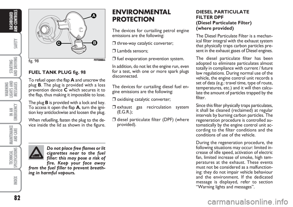
FUEL TANK PLUG fig. 98
To refuel open the flap Aand unscrew the
plug B. The plug is provided with a loss
prevention device Cwhich secures it to
the flap, thus making it impossible to lose.
The plug Bis provided with a lock and key.
To access it open the flap A, turn the igni-
tion key anticlockwise and loosen the plug.
When refuelling, fasten the plug to the de-
vice inside the lid as shown in the figure.
ENVIRONMENTAL
PROTECTION
The devices for curtailing petrol engine
emissions are the following:
❒three-way catalytic converter;
❒Lambda sensors;
❒fuel evaporation prevention system.
In addition, do not let the engine run, even
for a test, with one or more spark plugs
disconnected.
The devices for curtailing diesel fuel en-
gine emissions are the following:
❒oxidising catalytic converter;
❒exhaust gas recirculation system
(E.G.R.);
❒diesel particulate filter (DPF) (where
provided).
fig. 98
C
A
F0T0068m
Do not place free flames or lit
cigarettes near to the fuel
filler: this may pose a risk of
fire. Keep your face away
from the fuel filler to prevent breath-
ing in harmful vapours.
DIESEL PARTICULATE
FILTER DPF
(Diesel Particulate Filter)
(where provided)
The Diesel Particulate Filter is a mechan-
ical filter integral with the exhaust system
that physically traps carbon particles pre-
sent in the exhaust gases of Diesel engines.
The diesel particulate filter has been
adopted to eliminate particulates almost
totally in compliance with current / future
law regulations. During normal use of the
vehicle, the engine control unit records a
set of data (e.g.: travel time, type of route,
temperatures, etc.) and it will then calcu-
late the amount of particles trapped by the
filter.
Since this filter physically traps particulates,
it shall be cleaned (reclaimed) at regular
intervals by burning carbon particles. The
regeneration procedure is controlled au-
tomatically by the engine control unit ac-
cording to the filter conditions and the
conditions of use of the vehicle.
During the regeneration procedure, the
following situations may occur: limited in-
crease of idle speed, activation of electric
fan, limited increase of smoke, high tem-
peratures at the exhaust. These events
must not be considered as a malfunction-
ing: they do not impair vehicle behaviour
and the environment. If the dedicated
message is displayed, refer to section
“Warning lights and messages”.
Page 98 of 210
97
STARTING
AND DRIVING
WARNING
LIGHTS AND
MESSAGES
IN AN
EMERGENCY
MAINTENANCE
AND CARE
TECHNICAL
SPECIFICATIONS
INDEX
DASHBOARDAND CONTROLS
SAFETY
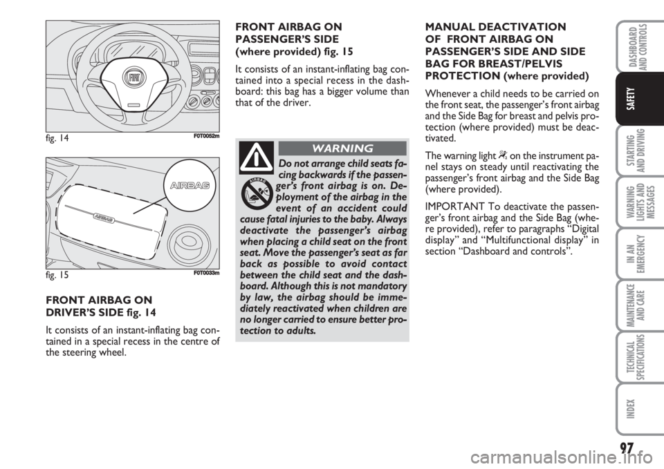
FRONT AIRBAG ON
DRIVER’S SIDE fig. 14
It consists of an instant-inflating bag con-
tained in a special recess in the centre of
the steering wheel.
fig. 14F0T0052m
fig. 15F0T0033m
FRONT AIRBAG ON
PASSENGER’S SIDE
(where provided) fig. 15
It consists of an instant-inflating bag con-
tained into a special recess in the dash-
board: this bag has a bigger volume than
that of the driver.
Do not arrange child seats fa-
cing backwards if the passen-
ger’s front airbag is on. De-
ployment of the airbag in the
event of an accident could
cause fatal injuries to the baby. Always
deactivate the passenger’s airbag
when placing a child seat on the front
seat. Move the passenger’s seat as far
back as possible to avoid contact
between the child seat and the dash-
board. Although this is not mandatory
by law, the airbag should be imme-
diately reactivated when children are
no longer carried to ensure better pro-
tection to adults.
WARNING
MANUAL DEACTIVATION
OF FRONT AIRBAG ON
PASSENGER’S SIDE AND SIDE
BAG FOR BREAST/PELVIS
PROTECTION (where provided)
Whenever a child needs to be carried on
the front seat, the passenger’s front airbag
and the Side Bag for breast and pelvis pro-
tection (where provided) must be deac-
tivated.
The warning light
“on the instrument pa-
nel stays on steady until reactivating the
passenger’s front airbag and the Side Bag
(where provided).
IMPORTANT To deactivate the passen-
ger’s front airbag and the Side Bag (whe-
re provided), refer to paragraphs “Digital
display” and “Multifunctional display” in
section “Dashboard and controls”.