sensor FIAT FIORINO 2007 Owner handbook (in English)
[x] Cancel search | Manufacturer: FIAT, Model Year: 2007, Model line: FIORINO, Model: FIAT FIORINO 2007Pages: 210, PDF Size: 3.22 MB
Page 5 of 210
4
SAFETY
STARTING
AND DRIVING
WARNING
LIGHTS AND
MESSAGES
IN AN
EMERGENCY
MAINTENANCE
AND CARE
TECHNICAL
SPECIFICATIONS
INDEX
DASHBOARD
AND CONTROLSDASHBOARD........................................................................ 5
INSTRUMENT PANEL......................................................... 6
SYMBOLS ............................................................................... 7
THE FIAT CODE SYSTEM ................................................. 7
THE KEYS .............................................................................. 8
ALARM ................................................................................... 12
IGNITION DEVICE ............................................................. 14
INSTRUMENTS .................................................................... 15
DIGITAL DISPLAY ............................................................... 17
MULTIFUNCTIONAL DISPLAY ...................................... 22
TRIP COMPUTER ................................................................ 31
SEATS ...................................................................................... 33
PARTITIONS.......................................................................... 36
HEAD RESTRAINTS............................................................. 38
STEERING WHEEL .............................................................. 39
REARVIEW MIRRORS......................................................... 39
HEATING AND CLIMATE CONTROL SYSTEM ........ 41
HEATING AND VENTILATION...................................... 43
MANUAL CLIMATE CONTROL SYSTEM .................... 46EXTERNAL LIGHTS ............................................................ 49
WINDOW WASHING....................................................... 51
CEILING LIGHTS.................................................................. 53
CONTROLS........................................................................... 56
INTERIOR FITTINGS........................................................... 58
DOORS .................................................................................. 61
WINDOW WINDERS ....................................................... 66
BOOT ...................................................................................... 67
BONNET................................................................................. 70
ROOF RACK/SKI RACK .................................................... 72
HEADLIGHTS........................................................................ 73
ABS SYSTEM ......................................................................... 74
EOBD SYSTEM ..................................................................... 76
PARKING SENSORS ........................................................... 77
SOUND SYSTEM.................................................................. 79
ELECTRICAL/ELECTRONIC DEVICES
INSTALLATION.................................................................... 80
VEHICLE REFUELLING........................................................ 81
ENVIRONMENTAL PROTECTION................................. 82
DD D
A A
S S
H H
B B
O O
A A
R R
D D
A A
N N
D D
C C
O O
N N
T T
R R
O O
L L
S S
Page 14 of 210
13
SAFETY
STARTING
AND DRIVING
WARNING
LIGHTS AND
MESSAGES
IN AN
EMERGENCY
MAINTENANCE
AND CARE
TECHNICAL
SPECIFICATIONS
INDEX
DASHBOARD
AND CONTROLS
DISABLING THE ALARM
Press button Ëon the key with the re-
mote control.
The following operations are performed
(excluding some versions):
❒the direction indicators turn on short-
ly twice;
❒two short beeps are produced by the
warning buzzer;
❒the doors are unlocked.
IMPORTANT If the central door locking
system is engaged using the metal insert
of the key, the alarm is not disabled.ANTI-LIFT PROTECTION
The anti-lift protection system consists in
a sensor which detects any change in ve-
hicle tilting with a view to identifying any
possible vehicle lifting, though partial (e.g.
when a tyre is removed).
The sensor also detects minor changes of
the vehicle trim angle both along the lon-
gitudinal and transverse axle.
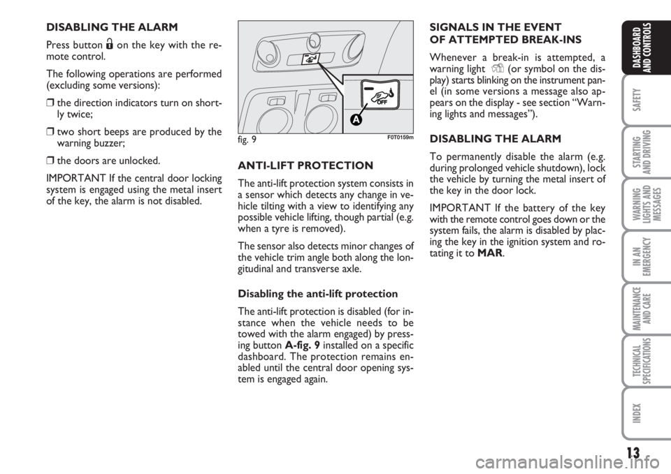
Disabling the anti-lift protection
The anti-lift protection is disabled (for in-
stance when the vehicle needs to be
towed with the alarm engaged) by press-
ing button A-fig. 9 installed on a specific
dashboard. The protection remains en-
abled until the central door opening sys-
tem is engaged again.SIGNALS IN THE EVENT
OF ATTEMPTED BREAK-INS
Whenever a break-in is attempted, a
warning light Y(or symbol on the dis-
play) starts blinking on the instrument pan-
el (in some versions a message also ap-
pears on the display - see section “Warn-
ing lights and messages”).
DISABLING THE ALARM
To permanently disable the alarm (e.g.
during prolonged vehicle shutdown), lock
the vehicle by turning the metal insert of
the key in the door lock.
IMPORTANT If the battery of the key
with the remote control goes down or the
system fails, the alarm is disabled by plac-
ing the key in the ignition system and ro-
tating it to MAR.
fig. 9F0T0159m
Page 78 of 210
77
SAFETY
STARTING
AND DRIVING
WARNING
LIGHTS AND
MESSAGES
IN AN
EMERGENCY
MAINTENANCE
AND CARE
TECHNICAL
SPECIFICATIONS
INDEX
DASHBOARD
AND CONTROLS
PARKING SENSORS
(where provided)
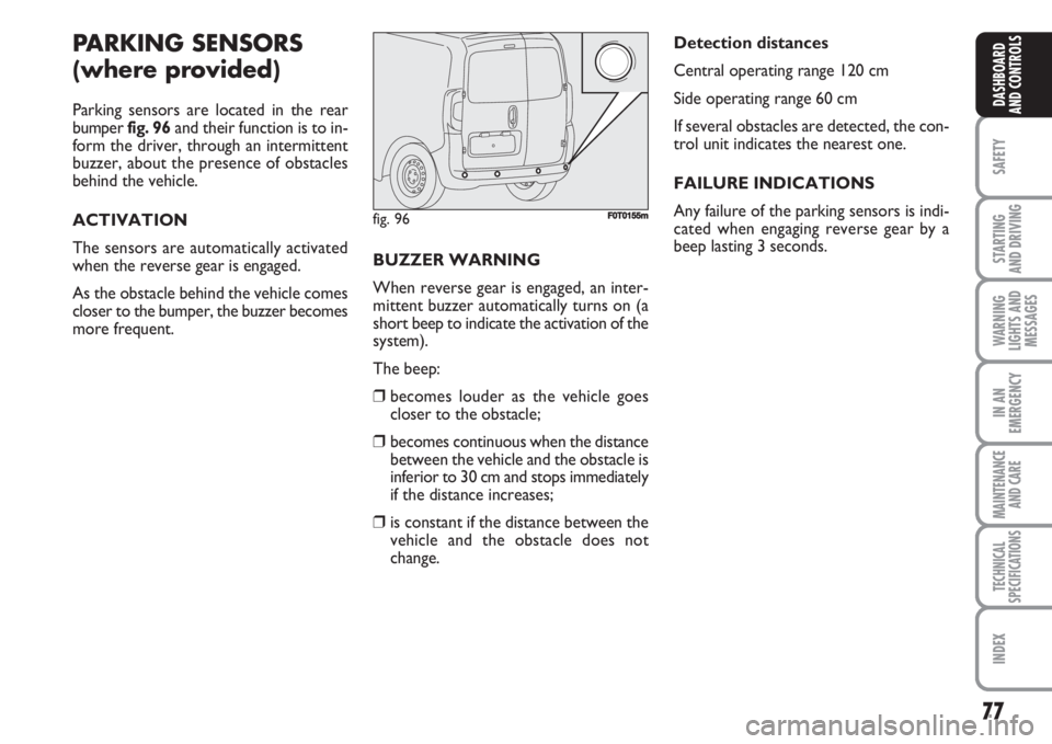
Parking sensors are located in the rear
bumper fig. 96and their function is to in-
form the driver, through an intermittent
buzzer, about the presence of obstacles
behind the vehicle.
ACTIVATION
The sensors are automatically activated
when the reverse gear is engaged.
As the obstacle behind the vehicle comes
closer to the bumper, the buzzer becomes
more frequent.BUZZER WARNING
When reverse gear is engaged, an inter-
mittent buzzer automatically turns on (a
short beep to indicate the activation of the
system).
The beep:
❒becomes louder as the vehicle goes
closer to the obstacle;
❒becomes continuous when the distance
between the vehicle and the obstacle is
inferior to 30 cm and stops immediately
if the distance increases;
❒is constant if the distance between the
vehicle and the obstacle does not
change.Detection distances
Central operating range 120 cm
Side operating range 60 cm
If several obstacles are detected, the con-
trol unit indicates the nearest one.
FAILURE INDICATIONS
Any failure of the parking sensors is indi-
cated when engaging reverse gear by a
beep lasting 3 seconds.
fig. 96F0T0155m
Page 79 of 210
78
SAFETY
STARTING
AND DRIVING
WARNING
LIGHTS AND
MESSAGES
IN AN
EMERGENCY
MAINTENANCE
AND CARE
TECHNICAL
SPECIFICATIONS
INDEX
DASHBOARD
AND CONTROLS
OPERATION
WITH TRAILER
Parking sensor operation is automatically
disabled when the electric cable plug of the
trailer is fitted into the vehicle tow hook
socket.
Sensors are automatically enabled again
when removing the trailer cable plug.GENERAL WARNINGS
❒When parking, take the utmost care to
obstacles that may be set above or un-
der the sensors.
❒Objects located near the vehicle back,
under certain circumstances, are not
detected and could therefore cause
damage to the vehicle or become dam-
aged.
❒Indications sent by the sensors can be
altered by dirt, snow or ice deposited
on the sensors or by ultrasound sys-
tems (e.g. truck pneumatic brakes or
pneumatic hammers) near the vehicle.
❒For correct parking sensor operation
the swing-doors must be closed. Open
swing-doors may produce incorrect in-
dications by the system. The rear doors
must always be closed. The sensors must be clean
from mud, dirt, snow or ice in
order to work correctly. Be
careful not to scratch or dam-
age the sensors while cleaning them.
Avoid using dry, rough or hard cloths.
Wash the sensors with clean water with
the addition of car shampoo, if neces-
sary. In washing stations, clean sensors
quickly keeping the vapour jet/high
pressure washing nozzles at 10 cm at
least from the sensors.
The driver is fully responsible
for parking operations and
other dangerous manoeuvres. Make
sure that no-one is standing in the
area, especially children or animals.
Parking sensors are designed to assist
drivers, who must always pay the ut-
most attention during potentially
dangerous manoeuvres even if they
are performed at low speed.
WARNING
Page 83 of 210
82
SAFETY
STARTING
AND DRIVING
WARNING
LIGHTS AND
MESSAGES
IN AN
EMERGENCY
MAINTENANCE
AND CARE
TECHNICAL
SPECIFICATIONS
INDEX
DASHBOARD
AND CONTROLS
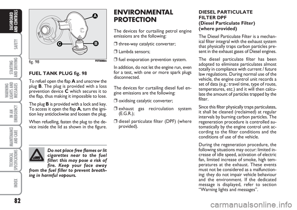
FUEL TANK PLUG fig. 98
To refuel open the flap Aand unscrew the
plug B. The plug is provided with a loss
prevention device Cwhich secures it to
the flap, thus making it impossible to lose.
The plug Bis provided with a lock and key.
To access it open the flap A, turn the igni-
tion key anticlockwise and loosen the plug.
When refuelling, fasten the plug to the de-
vice inside the lid as shown in the figure.
ENVIRONMENTAL
PROTECTION
The devices for curtailing petrol engine
emissions are the following:
❒three-way catalytic converter;
❒Lambda sensors;
❒fuel evaporation prevention system.
In addition, do not let the engine run, even
for a test, with one or more spark plugs
disconnected.
The devices for curtailing diesel fuel en-
gine emissions are the following:
❒oxidising catalytic converter;
❒exhaust gas recirculation system
(E.G.R.);
❒diesel particulate filter (DPF) (where
provided).
fig. 98
C
A
F0T0068m
Do not place free flames or lit
cigarettes near to the fuel
filler: this may pose a risk of
fire. Keep your face away
from the fuel filler to prevent breath-
ing in harmful vapours.
DIESEL PARTICULATE
FILTER DPF
(Diesel Particulate Filter)
(where provided)
The Diesel Particulate Filter is a mechan-
ical filter integral with the exhaust system
that physically traps carbon particles pre-
sent in the exhaust gases of Diesel engines.
The diesel particulate filter has been
adopted to eliminate particulates almost
totally in compliance with current / future
law regulations. During normal use of the
vehicle, the engine control unit records a
set of data (e.g.: travel time, type of route,
temperatures, etc.) and it will then calcu-
late the amount of particles trapped by the
filter.
Since this filter physically traps particulates,
it shall be cleaned (reclaimed) at regular
intervals by burning carbon particles. The
regeneration procedure is controlled au-
tomatically by the engine control unit ac-
cording to the filter conditions and the
conditions of use of the vehicle.
During the regeneration procedure, the
following situations may occur: limited in-
crease of idle speed, activation of electric
fan, limited increase of smoke, high tem-
peratures at the exhaust. These events
must not be considered as a malfunction-
ing: they do not impair vehicle behaviour
and the environment. If the dedicated
message is displayed, refer to section
“Warning lights and messages”.
Page 112 of 210
111
SAFETY
IN AN
EMERGENCY
MAINTENANCE
AND CARE
TECHNICAL
SPECIFICATIONS
INDEX
DASHBOARDAND CONTROLS
STARTING
AND DRIVING
WARNING
LIGHTS AND
MESSAGES
GENERAL WARNINGS..................................................... 112
LOW BRAKE FLUID........................................................... 112
HANDBRAKE ON.............................................................. 112
AIRBAG FAILURE................................................................ 113
FRONT PASSENGER AIRBAG/
SIDE BAGS DISABLED....................................................... 113
ENGINE COOLANT HIGH TEMPERATURE............... 114
LOW BATTERY CHARGE................................................ 114
ABS SYSTEM FAILURE....................................................... 115
EBD SYSTEM FAILURE....................................................... 115
LOW ENGINE OIL PRESSURE........................................ 115
EXHAUSTED OIL................................................................ 115
SEAT BELTS NOT FASTENED......................................... 116
INCOMPLETE DOOR LOCKING.................................. 116
MINIMUM ENGINE OIL LEVEL....................................... 116
INJECTION SYSTEM FAILURE......................................... 117
EOBD ENGINE CONTROL SYSTEM FAILURE ........... 117
PARTICULATE FILTER CLOGGED................................ 118FUEL RESERVE...................................................................... 118
GLOW PLUG HEATING................................................... 118
GLOW PLUG HEATING FAILURE................................. 118
WATER IN DIESEL FUEL FILTER.................................... 119
VEHICLE PROTECTION SYSTEM
FAILURE - FIAT CODE ...................................................... 119
EXTERNAL LIGHTS FAILURE.......................................... 119
GENERIC FAILURE INDICATION................................. 120
BRAKE PAD WEAR............................................................ 120
PARKING SENSOR FAILURE........................................... 121
SIDE/TAILLIGHTS................................................................ 121
FOLLOW ME HOME.......................................................... 121
FRONT FOG LIGHTS........................................................ 121
REAR FOG LIGHTS............................................................ 121
LEFT-HAND DIRECTION INDICATOR....................... 122
RIGHT-HAND DIRECTION INDICATOR................... 122
MAIN BEAMS........................................................................ 122
W W
A A
R R
N N
I I
N N
G G
L L
I I
G G
H H
T T
S S
A A
N N
D D
M M
E E
S S
S S
A A
G G
E E
S S
Page 121 of 210
120
SAFETY
IN AN
EMERGENCY
MAINTENANCE
AND CARE
TECHNICAL
SPECIFICATIONS
INDEX
DASHBOARDAND CONTROLS
STARTING
AND DRIVING
WARNING
LIGHTS AND
MESSAGES
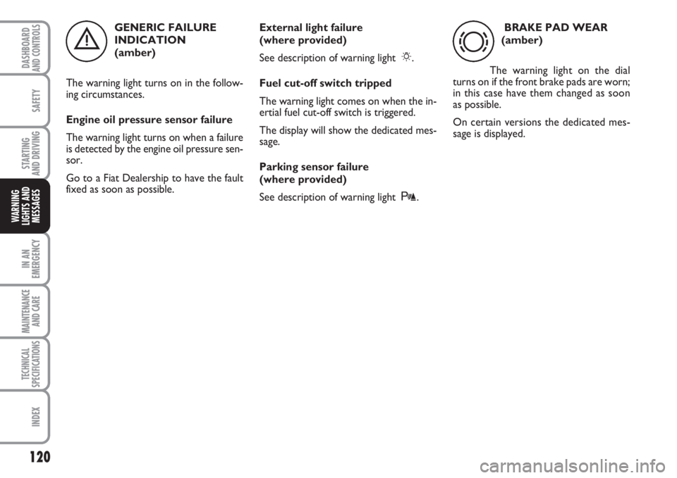
GENERIC FAILURE
INDICATION
(amber)
The warning light turns on in the follow-
ing circumstances.
Engine oil pressure sensor failure
The warning light turns on when a failure
is detected by the engine oil pressure sen-
sor.
Go to a Fiat Dealership to have the fault
fixed as soon as possible.External light failure
(where provided)
See description of warning light 6.
Fuel cut-off switch tripped
The warning light comes on when the in-
ertial fuel cut-off switch is triggered.
The display will show the dedicated mes-
sage.
Parking sensor failure
(where provided)
See description of warning light t.BRAKE PAD WEAR
(amber)
The warning light on the dial
turns on if the front brake pads are worn;
in this case have them changed as soon
as possible.
On certain versions the dedicated mes-
sage is displayed.
èd
Page 122 of 210
121
SAFETY
IN AN
EMERGENCY
MAINTENANCE
AND CARE
TECHNICAL
SPECIFICATIONS
INDEX
DASHBOARDAND CONTROLS
STARTING
AND DRIVING
WARNING
LIGHTS AND
MESSAGES
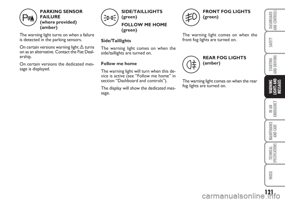
PARKING SENSOR
FAILURE
(where provided)
(amber)
The warning light turns on when a failure
is detected in the parking sensors.
On certain versions warning light èturns
on as an alternative. Contact the Fiat Deal-
ership.
On certain versions the dedicated mes-
sage is displayed.SIDE/TAILLIGHTS
(green)
FOLLOW ME HOME
(green)
Side/Taillights
The warning light comes on when the
side/taillights are turned on.
Follow me home
The warning light will turn when this de-
vice is active (see “Follow me home” in
section “Dashboard and controls”).
The display will show the dedicated mes-
sage.FRONT FOG LIGHTS
(green)
The warning light comes on when the
front fog lights are turned on.
REAR FOG LIGHTS
(amber)
The warning light comes on when the rear
fog lights are turned on.
t35
4
Page 150 of 210
149
SAFETY
MAINTENANCE
AND CARE
TECHNICAL
SPECIFICATIONS
INDEX
DASHBOARDAND CONTROLS
STARTING
AND DRIVING
WARNING
LIGHTS AND
MESSAGES
IN AN
EMERGENCY
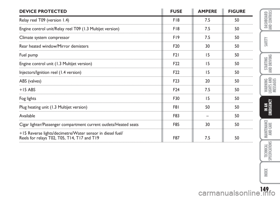
DEVICE PROTECTED FUSE AMPERE FIGURE
Relay reel T09 (version 1.4) F18 7.5 50
Engine control unit/Relay reel T09 (1.3 Multijet version) F18 7.5 50
Climate system compressor F19 7.5 50
Rear heated window/Mirror demisters F20 30 50
Fuel pump F21 15 50
Engine control unit (1.3 Multijet version) F22 15 50
Injectors/Ignition reel (1.4 version) F22 15 50
ABS (valves) F23 20 50
+15 ABS F24 7.5 50
Fog lights F30 15 50
Plug heating unit (1.3 Multijet version) F81 50 50
Available F83 – 50
Cigar lighter/Passenger compartment current outlets/Heated seats F85 30 50
+15 Reverse lights/decimetre/Water sensor in diesel fuel/
Reels for relays T02, T05, T14, T17 and T19 F87 7.5 50
Page 152 of 210
151
SAFETY
MAINTENANCE
AND CARE
TECHNICAL
SPECIFICATIONS
INDEX
DASHBOARDAND CONTROLS
STARTING
AND DRIVING
WARNING
LIGHTS AND
MESSAGES
IN AN
EMERGENCY
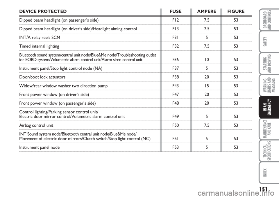
DEVICE PROTECTED FUSE AMPERE FIGURE
Dipped beam headlight (on passenger’s side) F12 7.5 53
Dipped beam headlight (on driver’s side)/Headlight aiming control F13 7.5 53
INT/A relay reels SCM F31 5 53
Timed internal lighting F32 7.5 53
Bluetooth sound system/central unit node/Blue&Me node/Troubleshooting outlet
for EOBD system/Volumetric alarm control unit/Alarm siren control unit F36 10 53
Instrument panel/Stop light control node (NA) F37 5 53
Door/boot lock actuators F38 20 53
Widow/rear window washer two direction pump F43 15 53
Front power window (on driver’s side) F47 20 53
Front power window (on passenger’s side) F48 20 53
Control lighting/Parking sensor control unit/
Electric door mirror control/Volumetric alarm control unit F49 5 53
Airbag control unit F50 7.5 53
INT Sound system node/Bluetooth central unit node/Blue&Me node/
Movement of electric door mirrors/Clutch switch/Stop light control (NC) F51 5 53
Instrument panel node F53 5 53