lock FIAT FIORINO 2010 Owner handbook (in English)
[x] Cancel search | Manufacturer: FIAT, Model Year: 2010, Model line: FIORINO, Model: FIAT FIORINO 2010Pages: 210, PDF Size: 4.9 MB
Page 18 of 210
17
SAFETY
STARTING
AND DRIVING
WARNING
LIGHTS AND
MESSAGES
IN AN
EMERGENCY
MAINTENANCE
AND CARE
TECHNICAL
SPECIFICATIONS
INDEX
DASHBOARD
AND CONTROLS
SETUP MENU fig. 15
The menu comprises a series of functions
arranged in a cycle which can be selected
through buttons +and –, thus gaining ac-
cess to the different select and setting (set-
up) operations given in the following para-
graphs.
The setup menu can be activated by briefly
pressing button MENU ESC.
Single presses on buttons +and –will
scroll the setup menu options.
Handling modes differ with each other ac-
cording to the characteristic of the option
selected.Selecting a menu option
– briefly press button MENU ESCto se-
lect the menu option to set;
– press buttons +and –(by single press-
es) to select the new setting;
– briefly press button MENU ESCto
store the new setting and go back to the
previously selected menu option.
Selecting “Set Clock”
– briefly press button MENU ESCto se-
lect the first value to change (hours);
– press buttons +and –(by single press-
es) to select the new setting;
– briefly press button MENU ESCto
store the new setting and go to the next
setup menu option (minutes);
– after setting the values with the same
procedure, go back to the menu item pre-
viously selected.Prolonged pressing of MENU ESC button
– to quit the setup menu if you are in the
menu;
– to quit the displayed menu if you are set-
ting an option;
– to save the changes to stored settings (and
confirmed by pressing button MENU
ESC).
The setup menu environment is timed;
when quitting the menu due to timing ex-
piry, only the settings stored by the user
are saved (and confirmed by briefly press-
ing button MENU ESC).
001-035 Fiorino GB 1ed:001-035 Fiorino GB 1ed 2-12-2009 16:14 Pagina 17
Page 20 of 210
19
SAFETY
STARTING
AND DRIVING
WARNING
LIGHTS AND
MESSAGES
IN AN
EMERGENCY
MAINTENANCE
AND CARE
TECHNICAL
SPECIFICATIONS
INDEX
DASHBOARD
AND CONTROLS
Setting the speed limit (SPEEd)
This function is used to set the vehicle
speed limit (km/h or mph); when this lim-
it is exceeded the driver is immediately
alerted (see section “Warning lights and
messages”).
To set the speed limit, proceed as follows:
– briefly press button MENU ESC, the
message (SPEEd) and the previously set
unit (km/h) or (mph) will appear on the
display;
– press button+or –to select speed lim-
it activation (On) or deactivation (OFF);
– if the function has been activated (On),
press buttons +or –to select the re-
quired speed limit and then press MENU
ESCto confirm;
NoteThe speed may be set in the range
from 30 to 200 km/h, or from 20 to 125
mph according to the previously chosen
unit (see “Setting the distance unit”) de-
scribed below. The setting will in-
crease/decrease by five units each time
button +/–is pressed. Hold button +/–
pressed to increase/decrease the setting
rapidly. When close to the desired value,
press the button as many times as re-
quired to complete the regulation.– Briefly press button MENU ESCto go
back to the menu screen or press the but-
ton for long to go back to the standard
screen without storing settings.
To cancel the setting, proceed as follows:
– briefly press button MENU ESC: (On)
will flash on the display;
– press button –: (Off) will flash on the dis-
play;
– briefly press button MENU ESCto go
back to the menu screen or press the but-
ton for long to go back to the standard
screen without storing settings.
Setting the clock (Hour)
With this function it is possible to set the
clock.
To set the required unit proceed as fol-
lows:
– briefly press button MENU ESC,
“hours” will flash on the display;
– press button +or –for setting;
– briefly press button MENU ESC: the
“minutes” start flashing on the display;
– press the button +or –to set the de-
sired value;
– briefly press button MENU ESCto go
back to the menu screen or press the but-
ton for long to go back to the standard
screen without storing settings.Adjusting the buzzer volume
(bUZZ)
This function is used to adjust the volume
of the buzzer triggering in the event of fail-
ure/warning indications and when MENU
ESC,+and –buttons are pressed.
To adjust the desired volume proceed as
follows:
– briefly press button MENU ESC, the
display will show the wording (bUZZ);
– press button +or –to select the re-
quired volume (volume can be adjusted ac-
cording to 8 levels).
– briefly press button MENU ESCto go
back to the menu screen or press the but-
ton for long to go back to the standard
screen without storing settings.
001-035 Fiorino GB 1ed:001-035 Fiorino GB 1ed 2-12-2009 16:14 Pagina 19
Page 22 of 210
21
SAFETY
STARTING
AND DRIVING
WARNING
LIGHTS AND
MESSAGES
IN AN
EMERGENCY
MAINTENANCE
AND CARE
TECHNICAL
SPECIFICATIONS
INDEX
DASHBOARD
AND CONTROLS
MULTIFUNCTIONAL
DISPLAY
(for versions/markets, where provided)
The vehicle can be equipped with a mul-
tifunctional display that, according to the
settings made, will show useful informa-
tion when driving.
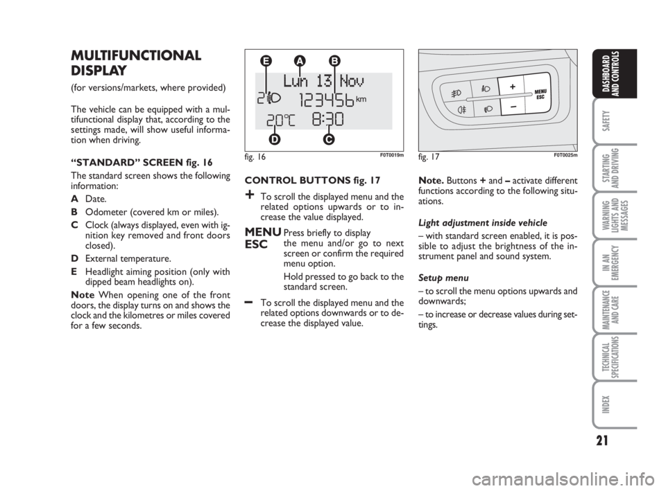
“STANDARD” SCREEN fig. 16
The standard screen shows the following
information:
ADate.
BOdometer (covered km or miles).
CClock (always displayed, even with ig-
nition key removed and front doors
closed).
DExternal temperature.
EHeadlight aiming position (only with
dipped beam headlights on).
NoteWhen opening one of the front
doors, the display turns on and shows the
clock and the kilometres or miles covered
for a few seconds.
fig. 16F0T0019mfig. 17F0T0025m
CONTROL BUTTONS fig. 17
+To scroll the displayed menu and the
related options upwards or to in-
crease the value displayed.
MENUPress briefly to display
ESCthe menu and/or go to next
screen or confirm the required
menu option.
Hold pressed to go back to the
standard screen.
–To scroll the displayed menu and the
related options downwards or to de-
crease the displayed value.Note.Buttons +and –activate different
functions according to the following situ-
ations.
Light adjustment inside vehicle
– with standard screen enabled, it is pos-
sible to adjust the brightness of the in-
strument panel and sound system.
Setup menu
– to scroll the menu options upwards and
downwards;
– to increase or decrease values during set-
tings.
001-035 Fiorino GB 1ed:001-035 Fiorino GB 1ed 2-12-2009 16:14 Pagina 21
Page 23 of 210
22
SAFETY
STARTING
AND DRIVING
WARNING
LIGHTS AND
MESSAGES
IN AN
EMERGENCY
MAINTENANCE
AND CARE
TECHNICAL
SPECIFICATIONS
INDEX
DASHBOARD
AND CONTROLS
Selecting an option of the main menu
with submenu
– Briefly press the button MENU ESCto
display the first submenu option.
– Press buttons +or –(by single press-
es) to scroll all the submenu options.
– Briefly press the button MENU ESCto
select the displayed submenu option and
open the relevant setup menu.
– Press buttons +or –(by single press-
es) to select the new setting for this sub-
menu option.
– Briefly press the button MENU ESC to
store the new setting and go back to the
previously selected submenu option. SETUP MENU fig. 18
The menu comprises a series of functions
arranged in a cycle which can be selected
through buttons +and –, thus gaining ac-
cess to the different select and setting (set-
up) operations given in the following para-
graphs. A submenu is provided for some
items (Clock and Unit setting).
The setup menu can be activated by briefly
pressing button MENU ESC.
Single presses on buttons +or –will scroll
the setup menu options.
Handling modes are different according to
the characteristic of the option selected.
Selecting an option of the main menu
without submenu
– Briefly press the button MENU ESCto
select the main menu option to set.
– Press buttons +or –(by single press-
es) to select the new setting.
– Briefly press the button MENU ESCto
store the new setting and go back to the
main menu option previously selected.Selecting the “Set Date” and “Set time”
– Briefly press button MENU ESCto se-
lect the first value to change (e.g. hours
/minutes or year / month / day).
– Press buttons +or –(by single press-
es) to select the new setting.
– Briefly press button MENU ESCto
store the new setting and go to the next
setup menu option: if this is the last one you
will go back to the previously selected op-
tion of the main menu.
Prolonged pressing of MENU ESC button
– to quit the setup menu if you are in the
main menu;
– to quit the main menu if you are in an-
other point of the menu (e.g.: at submenu
option setting level, at submenu level or
at main menu option setting level);
– to save the changes to stored settings (and
confirmed by pressing button MENU
ESC).
The setup menu environment is timed;
when quitting the menu due to timing ex-
piry, only the settings stored by the user
are saved (and confirmed by briefly press-
ing button MENU ESC).
001-035 Fiorino GB 1ed:001-035 Fiorino GB 1ed 2-12-2009 16:14 Pagina 22
Page 26 of 210
25
SAFETY
STARTING
AND DRIVING
WARNING
LIGHTS AND
MESSAGES
IN AN
EMERGENCY
MAINTENANCE
AND CARE
TECHNICAL
SPECIFICATIONS
INDEX
DASHBOARD
AND CONTROLS
– when accessing the “Mode” submenu:
briefly press button MENU ESC : the
previously set display mode will flash on
the display;
– press button +or –to select “24h” or
“12h”.
When you have made the required set-
tings, briefly press button MENU ESC
to go back to the menu screen or press
the button for long to go back to the stan-
dard screen without storing settings.
– hold MENU ESCpressed to go back
to the standard screen or main menu ac-
cording to the points of the menu where
you are at. Setting the clock (Set time)
This function enables clock setting using
two submenus: “Time” and “Mode”.
Proceed as follows:
– briefly press button MENU ESC, the
display will show the two sub-menus
“Time” and “Mode”;
– press button +or –to surf the two sub-
menus;
– select the required option and then
press button MENU ESC briefly;
– when accessing the “Hour” submenu:
briefly press button MENU ESC, the
“hours” will flash on the display;
– press button +or –for setting;
– briefly press button MENU ESC, the
“minutes” will flash on the display;
– press button +or –for setting;Set date (Set date)
This function enables updating the date
(day - month - year).
To update the date proceed as follows:
– briefly press button MENU ESC: “day”
will flash on the display;
– press button +or –for setting;
– briefly press button MENU ESC:
“month” will flash on the display;
– press button +or –for setting;
– briefly press button MENU ESC:
“year” will flash on the display;
– press button +or –for setting.
NoteThe setting increases or decreases
by one unit each time button +or – is
pressed. Hold the button pressed to in-
crease/decrease the setting rapidly. Com-
plete the setting by briefly pressing the
button when the required setting is ap-
proached.
– Briefly press button MENU ESCto go
back to the menu screen or press the but-
ton for long to go back to the standard
screen without storing settings.
001-035 Fiorino GB 1ed:001-035 Fiorino GB 1ed 2-12-2009 16:14 Pagina 25
Page 27 of 210
26
SAFETY
STARTING
AND DRIVING
WARNING
LIGHTS AND
MESSAGES
IN AN
EMERGENCY
MAINTENANCE
AND CARE
TECHNICAL
SPECIFICATIONS
INDEX
DASHBOARD
AND CONTROLS
Automatic central door locking
with vehicle running (Autoclose)
When activated (On), this function auto-
matically locks the doors when the vehi-
cle speed exceeds 5 km/h.
To activate (On) or to deactivate (Off) this
function proceed as follows:
– briefly press button MENU ESCto dis-
play one sub-menu;
– briefly press button MENU ESC: (On)
or (Off) will flash on the display (accord-
ing to previous setting);
– press button +or –for setting;
– briefly press button MENU ESCto go
back to the submenu screen or press the
button for long to go back to the standard
screen without storing settings;
– hold MENU ESCpressed to go back
to the standard screen or main menu ac-
cording to the points of the menu where
you are at. Audio repetition (See radio)
This function enables viewing information
regarding the sound system on the display.
– Radio: tuned radio station frequency or
RDS message, automatic tuning activation
or AutoSTore;
– Audio CD, MP3 CD: track number;
– CD Changer: CD number and track
number.
To activate (On) or to deactivate (Off)
sound system info displaying proceed as
follows:
– briefly press MENU ESC: (On) or (Off)
will flash on the display (according to pre-
vious setting);
– press button +or –for setting;
– briefly press button MENU ESCto go
back to the menu screen or press the but-
ton for long to go back to the standard
screen without storing settings.Set units (Units)
This function may be used to set the mea-
surement unit in three submenus: “Dis-
tances”, “Consumption” and “Tempera-
ture”.
To set the required unit proceed as follows:
– briefly press button MENU ESCto dis-
play the three sub-menus;
– press button +or –to browse the three
sub-menus;
– select the required submenu and then
briefly press button MENU ESC;
– when accessing the “Distances”submenu:
briefly press MENU ESC: either “km” or
“mi” will appear on the display (according
to the previous setting);
– press button +or –for setting;
– when accessing the “Consumption”submenu:
briefly press MENU ESC: either “km/l ”,
“l/100km” or “mpg” will appear on the dis-
play (according to the previous setting);
001-035 Fiorino GB 1ed:001-035 Fiorino GB 1ed 2-12-2009 16:14 Pagina 26
Page 34 of 210
33
SAFETY
STARTING
AND DRIVING
WARNING
LIGHTS AND
MESSAGES
IN AN
EMERGENCY
MAINTENANCE
AND CARE
TECHNICAL
SPECIFICATIONS
INDEX
DASHBOARD
AND CONTROLS
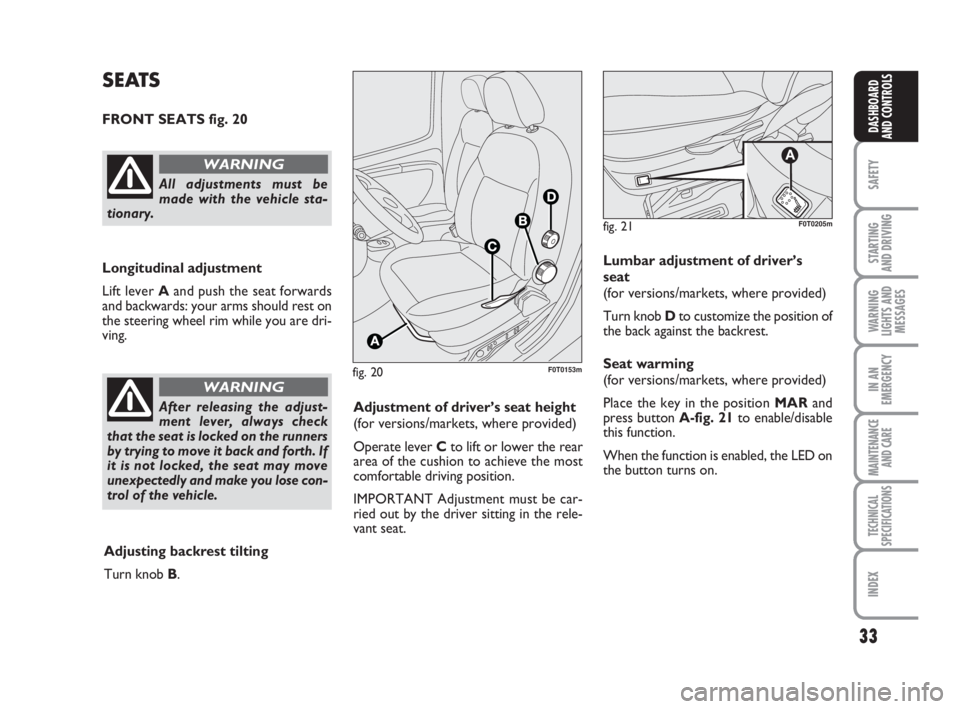
fig. 20F0T0153m
SEATS
FRONT SEATS fig. 20
Longitudinal adjustment
Lift lever Aand push the seat forwards
and backwards: your arms should rest on
the steering wheel rim while you are dri-
ving.
All adjustments must be
made with the vehicle sta-
tionary.
WARNING
After releasing the adjust-
ment lever, always check
that the seat is locked on the runners
by trying to move it back and forth. If
it is not locked, the seat may move
unexpectedly and make you lose con-
trol of the vehicle.
WARNING
Adjustment of driver’s seat height
(for versions/markets, where provided)
Operate lever Cto lift or lower the rear
area of the cushion to achieve the most
comfortable driving position.
IMPORTANT Adjustment must be car-
ried out by the driver sitting in the rele-
vant seat.
Adjusting backrest tilting
Turn knob B.Lumbar adjustment of driver’s
seat
(for versions/markets, where provided)
Turn knob Dto customize the position of
the back against the backrest.
Seat warming
(for versions/markets, where provided)
Place the key in the position MARand
press button A-fig. 21to enable/disable
this function.
When the function is enabled, the LED on
the button turns on.
fig. 21
A
F0T0205m
001-035 Fiorino GB 1ed:001-035 Fiorino GB 1ed 2-12-2009 16:14 Pagina 33
Page 39 of 210
38
SAFETY
STARTING
AND DRIVING
WARNING
LIGHTS AND
MESSAGES
IN AN
EMERGENCY
MAINTENANCE
AND CARE
TECHNICAL
SPECIFICATIONS
INDEX
DASHBOARD
AND CONTROLS
HEAD RESTRAINTS
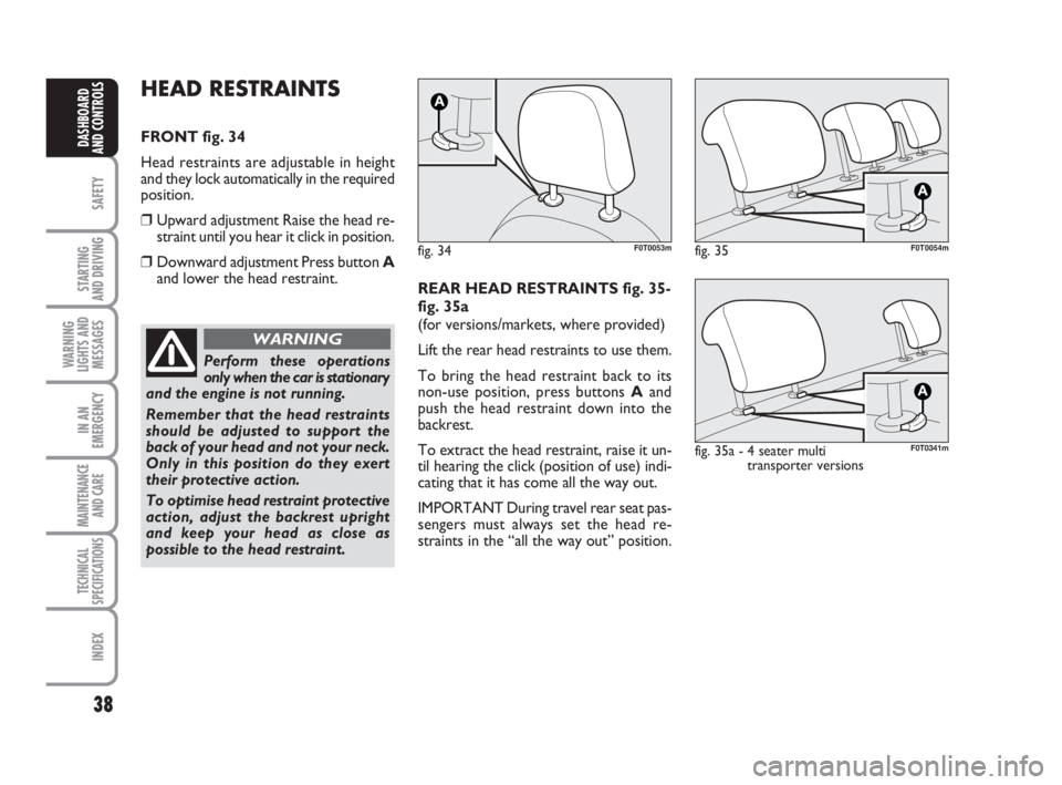
FRONT fig. 34
Head restraints are adjustable in height
and they lock automatically in the required
position.
❒Upward adjustment Raise the head re-
straint until you hear it click in position.
❒Downward adjustment Press button A
and lower the head restraint.
fig. 34F0T0053m
Perform these operations
only when the car is stationary
and the engine is not running.
Remember that the head restraints
should be adjusted to support the
back of your head and not your neck.
Only in this position do they exert
their protective action.
To optimise head restraint protective
action, adjust the backrest upright
and keep your head as close as
possible to the head restraint.
WARNING
REAR HEAD RESTRAINTS fig. 35-
fig. 35a
(for versions/markets, where provided)
Lift the rear head restraints to use them.
To bring the head restraint back to its
non-use position, press buttons Aand
push the head restraint down into the
backrest.
To extract the head restraint, raise it un-
til hearing the click (position of use) indi-
cating that it has come all the way out.
IMPORTANT During travel rear seat pas-
sengers must always set the head re-
straints in the “all the way out” position.
fig. 35F0T0054m
fig. 35a - 4 seater multi
transporter versions
A
F0T0341m
036-082 Fiorino GB 1ed:036-082 Fiorino GB 1ed 30-11-2009 15:46 Pagina 38
Page 40 of 210
39
SAFETY
STARTING
AND DRIVING
WARNING
LIGHTS AND
MESSAGES
IN AN
EMERGENCY
MAINTENANCE
AND CARE
TECHNICAL
SPECIFICATIONS
INDEX
DASHBOARD
AND CONTROLS
Perform these adjustments
only when the vehicle is sta-
tionary and the engine is not running.
WARNING
Under no circumstances
should aftermarket opera-
tions involving steering system or
steering column modifications (e.g.:
installation of anti-theft device) be
carried out that could badly affect
performance and safety. This also
causes the warranty to become null
and void and results in vehicle non-
compliance with type-approval re-
quirements.
WARNING
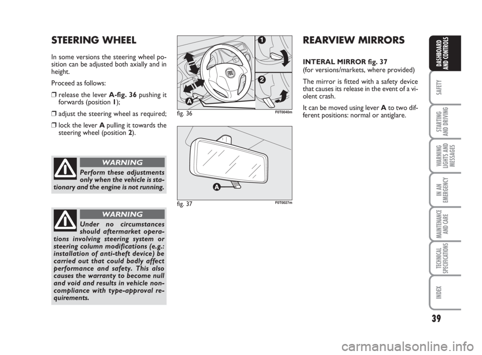
fig. 36F0T0040m
STEERING WHEEL
In some versions the steering wheel po-
sition can be adjusted both axially and in
height.
Proceed as follows:
❒release the lever A-fig. 36pushing it
forwards (position 1);
❒adjust the steering wheel as required;
❒lock the lever Apulling it towards the
steering wheel (position2).
REARVIEW MIRRORS
INTERAL MIRROR fig. 37
(for versions/markets, where provided)
The mirror is fitted with a safety device
that causes its release in the event of a vi-
olent crash.
It can be moved using lever Ato two dif-
ferent positions: normal or antiglare.
fig. 37F0T0027m
036-082 Fiorino GB 1ed:036-082 Fiorino GB 1ed 30-11-2009 15:46 Pagina 39
Page 41 of 210
40
SAFETY
STARTING
AND DRIVING
WARNING
LIGHTS AND
MESSAGES
IN AN
EMERGENCY
MAINTENANCE
AND CARE
TECHNICAL
SPECIFICATIONS
INDEX
DASHBOARD
AND CONTROLS
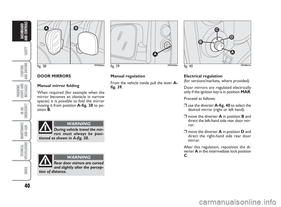
fig. 38F0T0042m
During vehicle travel the mir-
rors must always be posi-
tioned as shown in A-fig. 38.
WARNING
fig. 39F0T0194mfig. 40
B
C
D
F0T0041m
Manual regulation
From the vehicle inside pull the lever A-
fig. 39. DOOR MIRRORS
Manual mirror folding
When required (for example when the
mirror becomes an obstacle in narrow
spaces) it is possible to fold the mirror
moving it from position A-fig. 38to po-
sition B.Electrical regulation
(for versions/markets, where provided)
Door mirrors are regulated electrically
only if the ignition key is in position MAR.
Proceed as follows:
❒use the diverter A-fig. 40to select the
desired mirror (right or left hand):
❒move the diverter Ain position Band
direct the left-hand side rear door mir-
ror;
❒move the diverter Ain position Dand
direct the right-hand side rear door
mirror.
After this regulation, reposition the di-
verter Ain the intermediate lock position
C.
Rear door mirrors are curved
and slightly alter the percep-
tion of distance.
WARNING
036-082 Fiorino GB 1ed:036-082 Fiorino GB 1ed 30-11-2009 15:46 Pagina 40